

Tin The Friendly Robot
Made by louis-higgins / 3D Printing / Health / Notifications / Voice / IoT
About the project
A robot that can monitor your wellbeing and act upon what information it gathers, the Google AIY Vision and Voice Kits are used to add facial detection and voice interactivity to this project. The IFTTT service is used to send relevant notifications to your phone.
Project info
Difficulty: Moderate
Platforms: Autodesk, Google, Home Assistant, IFTTT, Raspberry Pi
Estimated time: 6 hours
License: GNU General Public License, version 3 or later (GPL3+)
Items used in this project
Hardware components

Software apps and online services
Hand tools and fabrication machines
Story
Overview
This project has been created to make sure that the person using it is happy; if they are not happy, it will do it's best to change how they are feeling. If the person using it is already happy, then it will do it's best to keep them that way.
Depending on how the user is feeling the robot can tell you a joke, suggest calling a family member or friend. It can also send a link to your phone recommending a playlist to the user or an exercise video or meditation, an audiobook, a radio station, a recipe or a random movie, video or game. It can also be used to turn on/off the RGB LED strip and set it to a specific colour. If the user is feeling particularly down and would like some help they can be recommended to Kooth, a free online support service.
When the robot asks how you are feeling it can recognise the following emotions; Happy, Sad, Anxious, Board, Angry and Insomnia.
The robot will also recognise if the user is happy or sad using the Joy Detection Demo, it will then act upon this by asking the user to choose from one of the options listed on the Happy/Sad paper.
I have also included 3d printer files to print an enclosure for the kits which makes them look more like a robot and therefore more friendly.
The first obvious step is to follow the instructions on https://aiyprojects.withgoogle.com/ this is where you can build the AIY Vision and Voice Kit, this is not a difficult process as long as you follow the steps carefully.
Setting up the vision kit
1. The first step when the pi is booted up is to stop the joy_detection service from running, this is set to run from boot and to edit the code, it cannot be running.
- sudo systemctl stop joy_detection_demo
2. You now need to change your working directory to the one of the joy detection python script, this will allow you to edit it. The easiest way that I have found is to go to the folder you want to be in and press F4 - this will open up a terminal window with the current directory already set, alternatively you could just use this command.
- cd ~/AIY-projects-python/src/examples/vision/joy
3. You will now need to overwrite the original joy detector demo with the new one I have uploaded, all you need to do is use CTRL + C to copy the file and then CTRL+V to paste the file in the joy directory and when it asks you if you want to overwrite the file press yes.
This is all that needs to be done for now, this vision kit will be revisited later in the tutorial.
Setting up the voice kit
Setting up the assistant and billing
1. Start by setting up the google assistant, this is explained well by this guide https://aiyprojects.withgoogle.com/voice/#google-assistant even though it says to use SSH I would recommed using a monitor and keyboard. I personally use the motorola lapdock with the relevant adapters. You could also use SSH and accomplish the same task.
This tutorial didn't work first time for me but I did miss a step so just make sure that you follow all of the steps and then it should work correctly.
Once this has been set up, you should have a fully working Google Assistant. Even though this step is not necessary I believe that it is a good way to make sure that all your hardware works and you are shown how to create a project in the Google Cloud Console. This will be needed for the next step.
2. You will now need to set up the Google Cloud Speech API, this is used so that we can capture what the person is saying into the microphone and initiate commands based on what they say.
This step will require you to enable billing on your Google account, Google gives you 60 minutes of free usage of the cloud speech API each month but after you have used all of this they will charge you $0.006 for every 15 seconds of usage, this is about £0.0046 at the time of writing.
Once again you can follow this tutorial
Throught the development of this project I have not gone over the free 60 minutes of usage so unless you are going to make this into a fully fledged product you will most likely not be charged.
Setting up IFTTT
In this project IFTTT (If This Then That) has been used constantly, I have used the Pushbullet service on there which enables notifications to be sent to your phone. This is the only notification service I found that opened a specified link when the notification was pressed.
I will now show you how to set up pushbullet and IFTTT
1. Open up IFTTT and sign in, create an account, if you do not already have one.
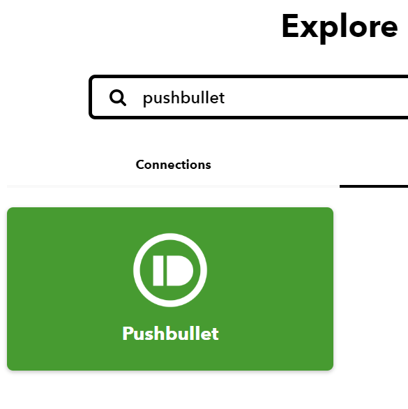
2. Go to the explore tab and type 'Pushbullet' you need to search in services rather than connections
3. Click on the pushbullet icon and press connect
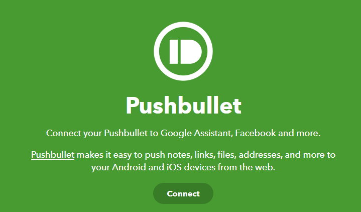
4. Install the pushbullet app on your phone and sign in with a Google or Facebook account,
Pushbullet app - Google Play Store
5. You can now press connect and it will direct you to a page where you can sign into your account that you linked to your pushbullet account.
5. Now we need to start creating applets, I will use the webhook and pushbullet service. Webhooks is a service that responds to a specific URL being pinged, this can be done by any device. I have found it easiest to use the requests library in python to ping the URL.
6. Press the create in the top right corner on the home page on IFTTT the page should look like the picture below.

7. Click on the word 'This' and search for Webhooks
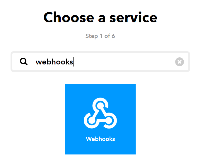
8. Now click on webhooks and press on the only option 'Recieve a web request'.
9. Now you need to create an event name, I called this happyPlay so type this in the text box and press create trigger.
10. You can now create the That service so press on the word 'That'.
11. Search for Pushbullet and press on the pushbullet icon.
12. Then press connect which will bring up a small window that grants IFTTT access to your pushbullet profile and data, just press approve.
13. Now press push a link.
14. Now enter the title and url of the notification I used Your playlist to cheer you up for the title and this link for the URL.
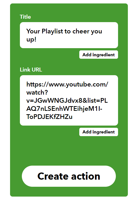
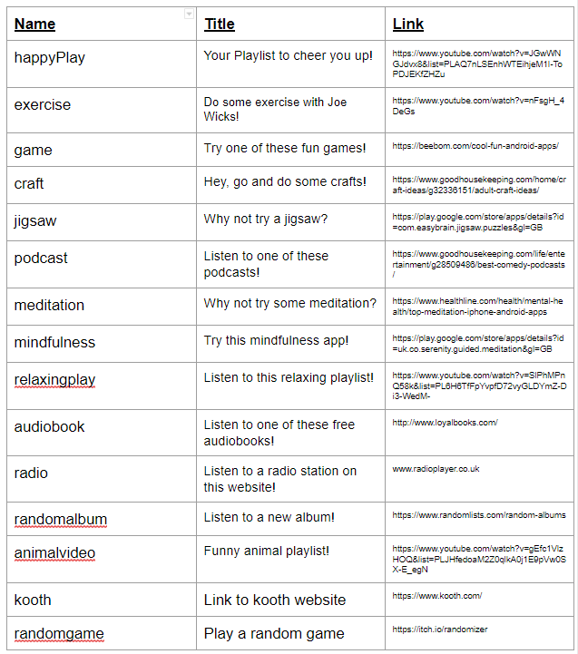
15. Now press create action, then give the applet a name and click finish.
16. You can now create 14 more applets for the other actions that are used in the program, the information below shows the information that I used, I have also provided a link to a Google Docs where you can copy and paste the information.
Set up the code
Now we need to get the code working on the voice kit
1. Download the code labled cloud_final.py.
2. Put this onto the raspberry pi, I recommend using a USB flash drive or you could go to this tutorial on the raspberry pi and press download directly on the pi. This will be saved in the /home/pi/Downloads folder.
3. Move this file to the home directory (/home/pi) and use the command below to move it into the correct folder
- mv cloud_final.py /home/pi/AIY-projects-python/src/examples/voice
4. You now need open this file in nano (a text editor built into the linux terminal) and change the URL variable to match your webhooks ID. You can find this by going to this link https://ifttt.com/maker_webhooks/settings
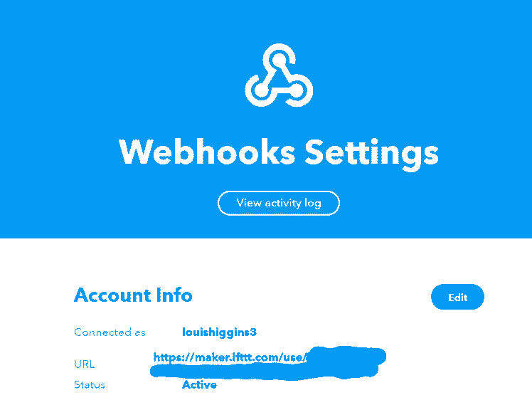
I have covered up my ID, this is the code that you need to paste in the variable named URL located just under the import section of the code
- URL = 'YOUR_WEBHOOKS_URL'
5. Now that this is done, you now need to make this python file executable, this can be done with the chmod command and the +x attribute to add the executable permission. Use the command below, make sure that your working directory is still where the python file is
- chmod +x cloud_final.py
6. If everything works you can run the file with
- ./cloud_final.py
7. You now need to make this program run on boot, this is not needed for the vision kit because we are just editing a service, not creating a new one. This is an easy thing to do and once again, Google explains how to do this perfectly in this tutorial
7. When you have set the program to run at boot you no longer have to deal with any more software, the software for both kits is now complete. Well done!
3D Printing
It is now time to build the case, I am using PLA plastic which is environmentally friendly plastic made from plant sugars.
This will be quite a large print with the total material usage being just over 40 meters with the settings listed below
0.4mm Nozzle Diameter
0.3mm Layer Height
Supports on
10% infill density
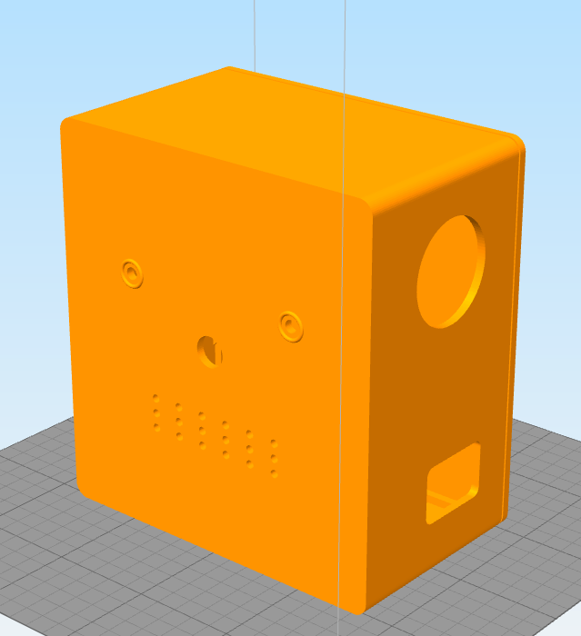
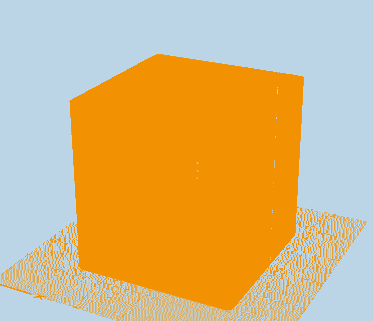
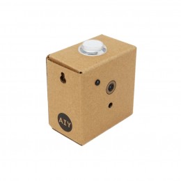
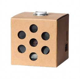
Above you can see screenshots of the two enclosures, I have designed them so the vision kit will sit on top of the voice kit.
I have also included the Fusion 360 files so if you want you can download them and see how I created it or edit it to maybe have a different design.
Assembly
It is now time for the assembly of the project, for this step you will need the 3d printed case, a soldering iron, the jumper cables, LED strip and something to clean up the 3d printed holes and make them the correct size.
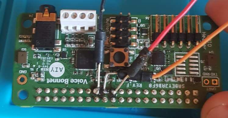
1. I started off by soldering the male to male jumper leads to GND, GPIO11 and GPIO9 of the Raspberry Pi, In this tutorial I will not show you how to solder but this is a great Soldering Tutorial that can help you. These cables can be wired to the Green, Pink and Cyan lines on the diagram below.
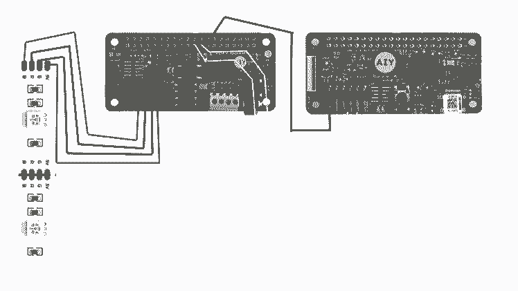
Once soldered it should look like this: The green wire is GND, orange GPIO11 and red GPIO9
2. Add some electrical tape over the contacts to prevent shorting out the pins and this should make the device more durable
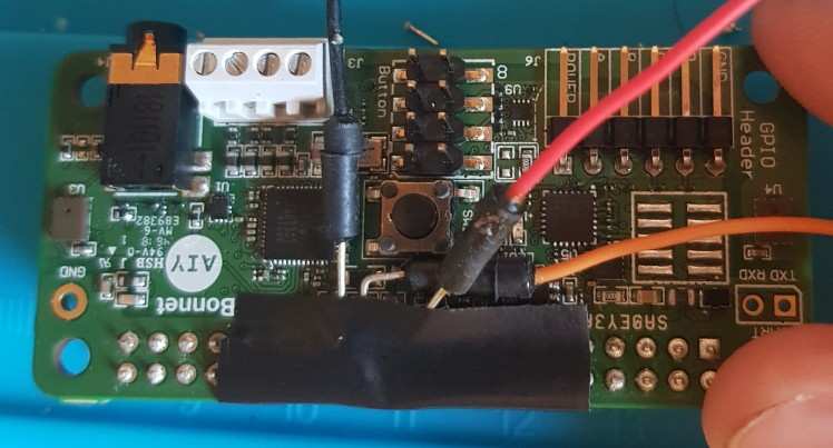
On the ends of unsoldered ends of the jumper leads I added a female to female jumper to each, this will give the wire enough length to reach the vision kit.
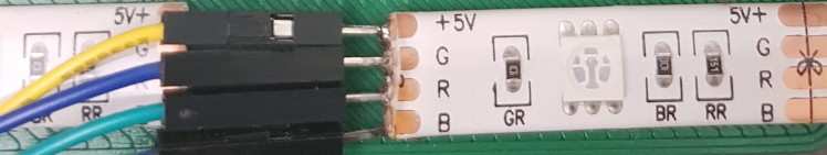
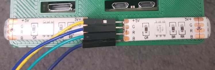
3. Now wire the LED strip according to the wire diagram with the 4 male to female jumper leads
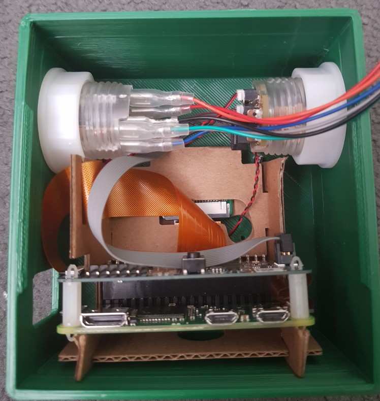
4. We can now start putting the kits into the 3d printed case, I have taken the outer cardboard off from the kits but left the electronics on the inner cardboard, this will act as the holder for the electronics.
You now have to modify the cardboard on the vision to allow the buttons to screw into place, all you need to do is cut to where the pictures have shown on both sides of the cardboard.
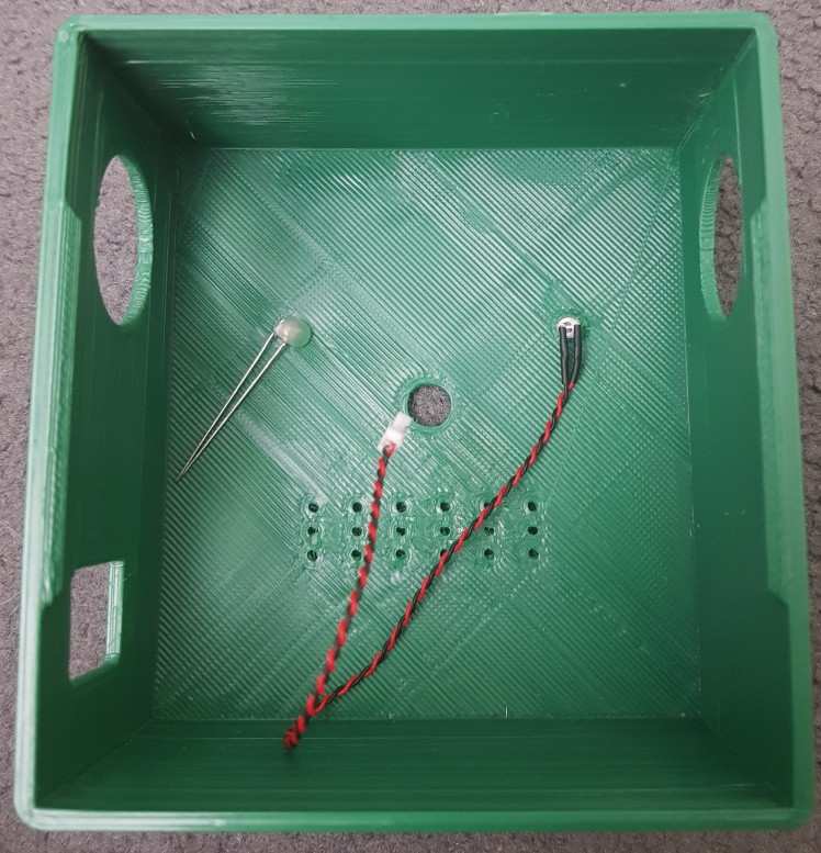
5. Now that you have done that we can place the LED's into the vision case enclosure, I have used the privacy LED that comes with the kit in one of the holes and a clear 3mm LED that I had laying around in the other LED, I have done this to make the LED's look like eyes for the robot. You can then add a little hot glue to secure the LED in place
6. You can now add the two arcade buttons that came with the kit, you should be able to screw them into the holes. Then add the nut on the inside to secure the button and prevent it from moving
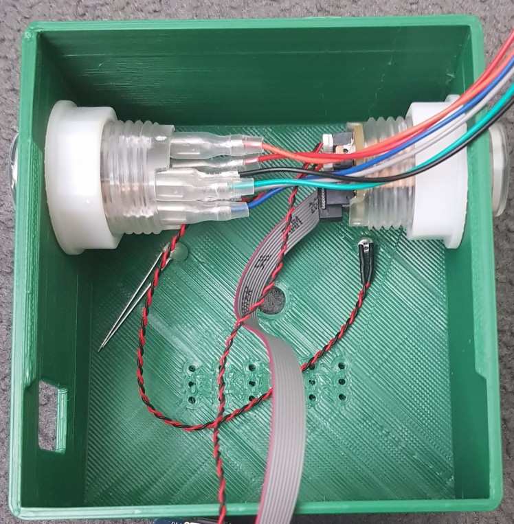
7. Now you can slide the cardboard into the enclosure making that nothing is covering the camera hole other than the actual camera. You can also wire up the button for the vision kit the same way as you did originally when following the Google tutorial
8. You should now feed the voice kit button wire through the small hole in the back and then clip the back of the case onto the front of the case. This is done by the clips that I designed into the front and back of the case.

The design for the case I have uploaded will look slightly different to this, the micro-USB port hole is taller, this is because it was not large enough to fit any of the micro-USB cables that I own to provide power. I did get past this by using a rotary tool with a cutting disk to enlarge the hole since I did not want to print it again.
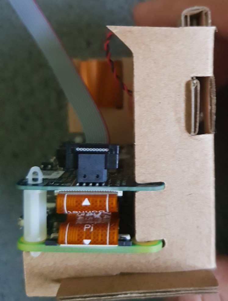
9. It it now time to place the voice kit into it's enclosure, this is by far the easiest, all you need to do is drop the cardboard into the enclosure with the Raspberry Pi ports side the same as the cutouts on the back.
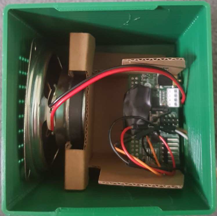
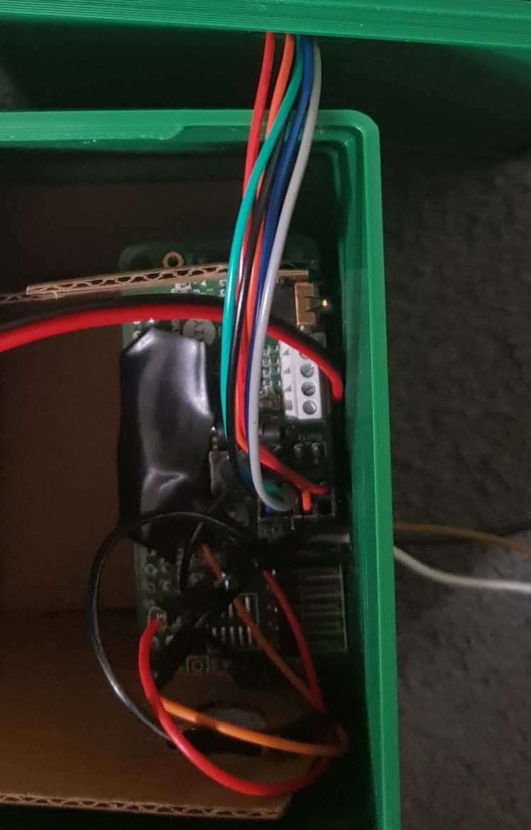
This is how it looks, all you need to do now is route the male to male jumper leads out of the GPIO cutout, these will be used to send a signal from the vison kit to the voice kit.
9. You can now take the voice button wires from the hole in the vision kit enclosure and plug it into the socket on the voice phat, you need route the cable through the hole on the voice hat lid and make sure that the connector is oriented the correct way, according to the picture below
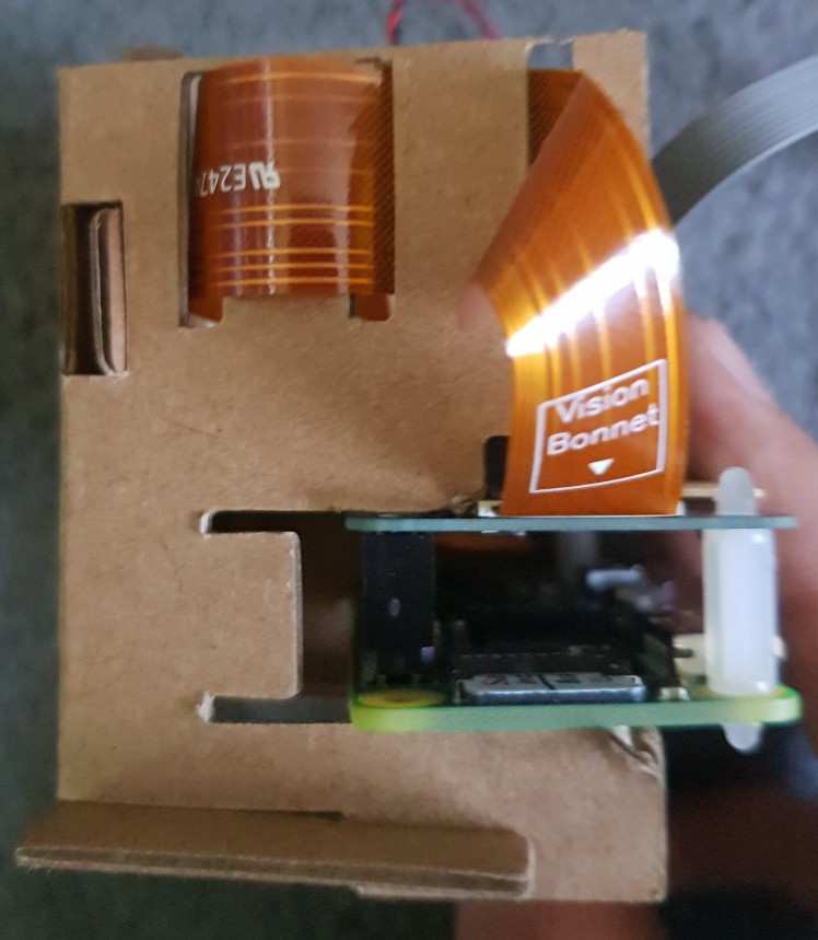
10. You can now close the lid on the voice kit enclosure using the snap in clasps and then place the vision kit on top of the voice kit. I prefer to place the vision kit in the middle of the top so it looks more interesting and more like a robot.
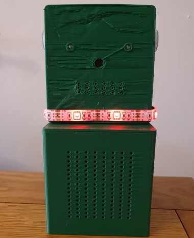
11. It is now time to add the LED strip in, I wrapped this around the base of the vision kit. I used in total around 30 cm of LED strip, mine was a common anode 5v led strip but you could use any other one as you supply enough power. Bear in mind that the Raspberry Pi can only provide 5v from the GPIO pins and I have found that even when only one colour is on it is not as bright as the LED strip can go. For this reason I would suggest that you get a RGBW strip rather than a RGB one, the difference is that there is a seperate LED dedicated to emmiting white light. When using a RGB strip to get the colour white you need to have all the colours R, G and B turned on, this demands a lot of power and you do not get a very bright light out of it.
I just used the adhesive included on the back of the LED strip, this stuck the strip onto the 3d printed case well enough.
12. You can now plug the relevant jumper leads into the correct GPIO space, you can refer to the wiring diagram again that was used in step 1 of the assembly process. Once done all you need to do is supply power and then both python programs should run from boot.

This is the finished project, the vision kit 3d print looks a bit weird because while printing I did not apply enough glue stick to the print bed, this is what I use to get the best adhesion to the bed. When you print the .stl files you will get a much cleaner result and it will look flat like the voice kit's front of the enclosure. Even though you can't see it in the photo above there are little arms on the side of the voice kit, this adds to the robot asthetic of the project, you can see this detail in the 3d printing step of the project.
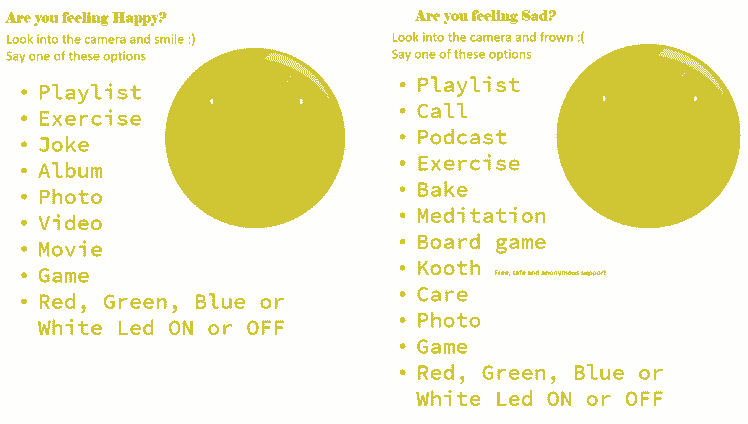
I have also created a design for a piece of paper, this shows the different options that the user has to choose from when prompted by Tin, there is also a clipart picture of a happy and sad face to indicate which side you are on. These images are royalty free and you can get them from Sad Face Link and Happy Face Link these images are both from pixabay.com which is a great website for royalty free images. You can see a picture of the piece of paper below
Videos!
The video above shows the first way that you can interact with Tin, this is by using the voice kit and the button on the right. You can see that the notification was sent to my phone and when I pressed it, a link to a calming playlist was opened.
This second video is showing the joy detection in action, even though you can't see it I am frowning at the camera and once it detects that I am you can hear a little beep from the buzzer. I ask it to turn the light on, I chose as it is easier to remember than 'LED on'. There is much more that this function can do and the ones that I have included are on the sheet of paper but you could easily add some more in the code.
Acknowledgements
Throughout this project the Google AIY website has been essential, It is explained in easy to follow steps and is easy to follow.
In the cloud_final.py program, I have used a joke program created by DerpyOmnister, you can find it here I have edited this code but credit still goes to DerpyOminister. I have added a link to the origional program in the code.
Final Thoughts
After playing around with this kit for hours on end, I can say that there is much more that can be with these kits; even if you don't complete the tutorial, you can still easily make a google assitant out of it. I have found that the pi zero is underpowered if you want to develop anything on it so while sorting out the code for the project I just took the phat of the Pi zero and placed it on one of my Pi 3's, this meant that everything ran much smoother. I believe that if you had a pi 3 powering the kit you could run the musical elements straight from the kit rather than by sending a notification to your phone.
Leave your feedback...