

Terminator Glasses

Made by 314Reactor / Lights / Sensors / Wearables
About the project
Adding a moving red eye to the iconic Terminator Glasses.
Project info
Difficulty: Easy
Platforms: Arduino, SparkFun, Pimoroni
Estimated time: 1 hour
License: GNU General Public License, version 3 or later (GPL3+)
Items used in this project
Hardware components


View all
Story
Tech Noir.
I’ve been thinking of making a pair of Terminator Glasses for a while now; basically I was thinking of having the red eye behind the glasses that would move around as the wearer looks about.
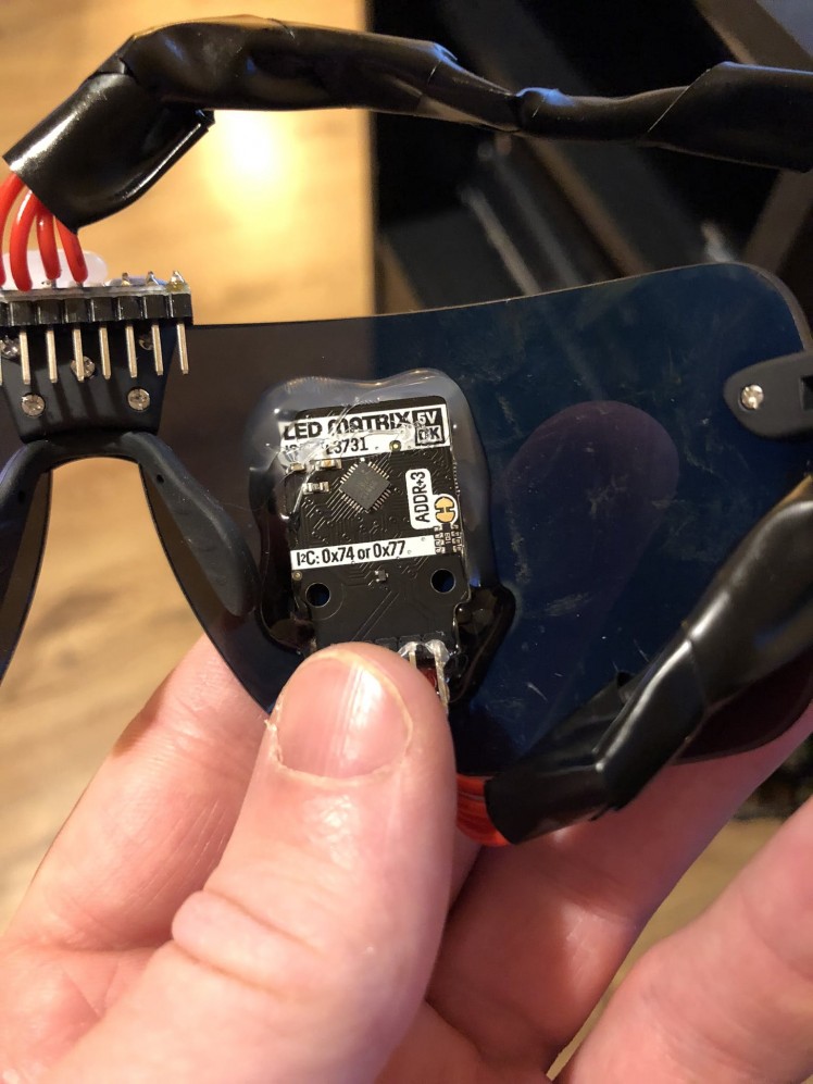
I was looking around for a good LED platform to use when I came across Pimoroni’s very handy looking 5×5 RGB LED matrix, so I got it purchased and got to work.
Key goals:
- Have a pair of glasses with the iconic Terminator red eye.
- Have the eye move when the glasses are moved in a direction.
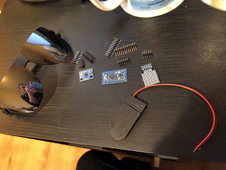
Parts.
- Arduino Pro Mini
- Terminator Glasses
- 5×5 RGB Breakout
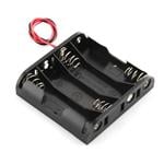
- Battery Holder
- Wire
- Veroboard
- MPU-6050
- CR2025 Batteries
- Electrical Tape
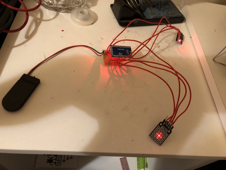
Building.
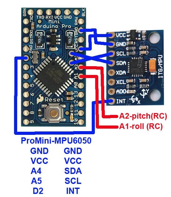
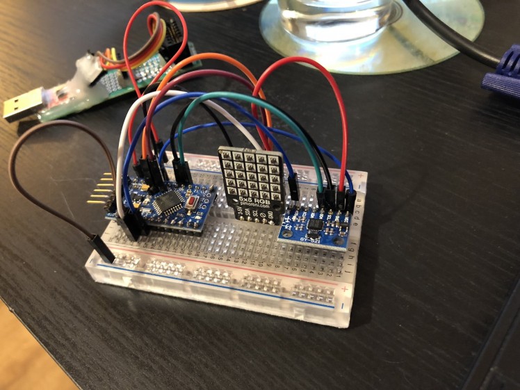
I wired up the MPU-6050 according to this diagram from this thread:
And then wired up the 5×5 RGB in the same way on a breadboard to test code and functionality.
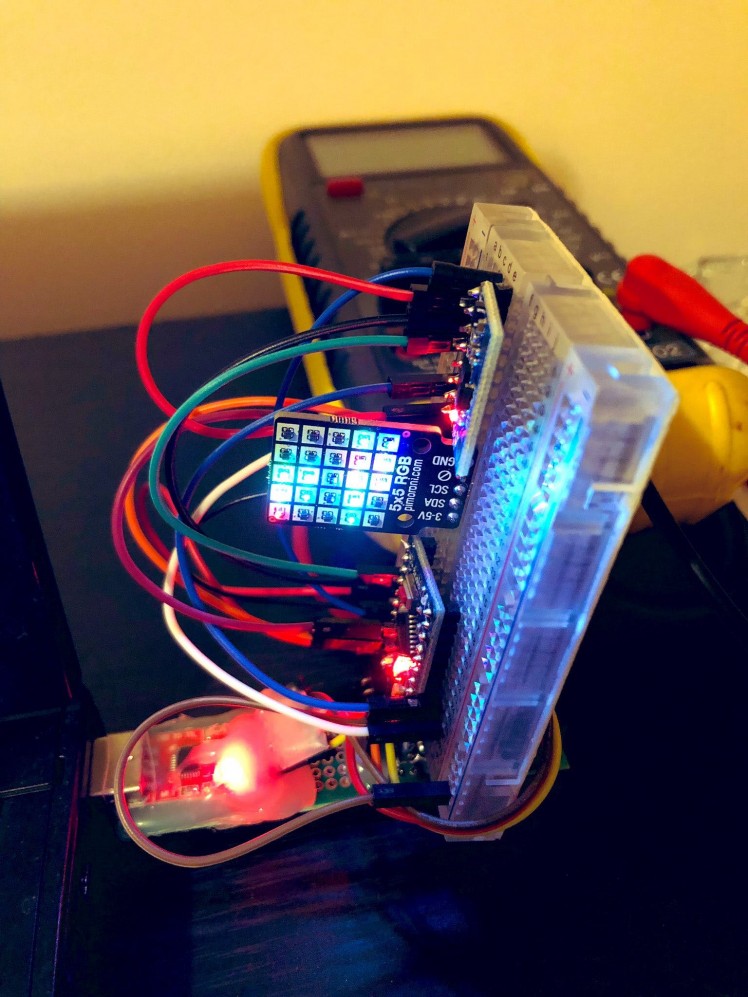
Running some example code to test the matrix:
I uploaded some test code to it and got the motion sensor working, the main issue I found is that while the RGB breakout is compatible with the Arduino there isn’t an easy to use library for it, as far as I could find – as above, there are example bits of code but these run through every x and y coordinate in various loops, so it’s difficult to directly see what pixels are being lit and when. I also think the examples aren’t fully compatible with the matrix as the patterns were odd.
So I loaded up the library for the microcontroller that is on the board – the IS31FL3731. You can directly write pixels using functions in the library but this one is really odd; I found there was no distinct pattern to the x, y coords being passed into the function and the result on the matrix.
So after painstaking trial and error I finally found out how the coords required to get each pixel red and mapped it out:
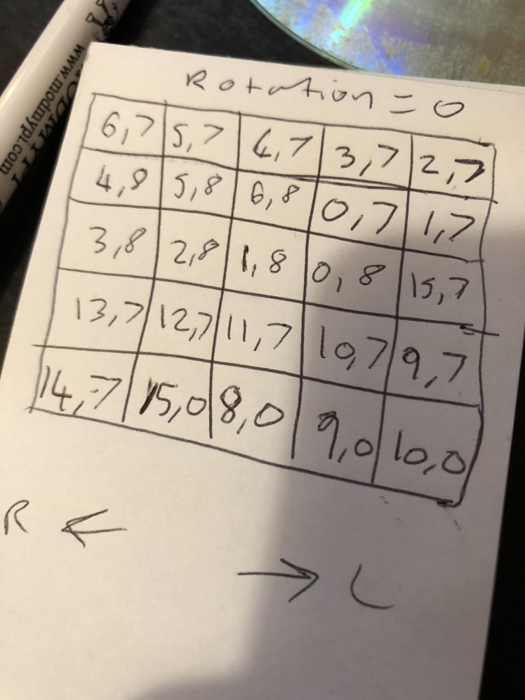
So if I want to light up the centre pixel I’d use:
// x, y and brightness passed into functionmatrix.drawPixel(1, 8, 128);I made it so there would be a central cross with lighter lit pixels around it – to try and form what would look more like an eye.
I then got to work on testing the gyro axis and seeing how they respond to left and right / up and down movements that the glasses would be making while someone is wearing them – the final code is on my GitHub.
The code detects whether the user is looking up, down, left or right and draws the ‘eye’ accordingly – so when the glasses are moving left the eye looks left – etc.
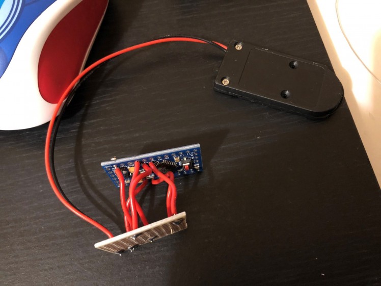
I then soldered in the wiring required on the Arduino itself:
Then wired up the matrix and the motion sensor, using a small piece of veroboard to share the VCC, GND, SDL and SCA lines:
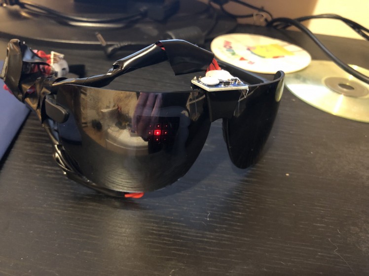
After a bit more testing on the glasses themselves I glued the apparatus onto the glasses and tidied up the wiring as much as I could with electrical tape:
 1 / 2
1 / 2
 1 / 2
1 / 2
Working.
This was too much fun. The eye looks great – although as you can see sometimes it flickers about quite a bit, sometimes the values coming from the motion sensor go a bit crazy, making the eye wobble a bit.
But overall it’s pretty much what I wanted.
Conclusion.
I’m very happy with this project, it looks very close to the Terminators red eye (only seen in the marketing, the actual film as far as I know doesn’t show it behind the glasses). It’s reactions, while sometimes being a bit weird and flickering about, looked really good and it was a lot of fun pretending to be the Terminator.
I may need to investigate a way to ignore strange spikes in the sensor readings to prevent the flickering mentioned above.
The main issue is the bulk added on with the electronics and battery – I tried to minimise the footprint by using an Arduino Pro Mini and the 2 coin cells batteries in the holder; but even then it still took up quite a bit of space.
I also need some more practice with getting wiring more hidden within the projects I make, this was another thing that took up a lot of space as there were a lot of wires required.
Let me know what you thought!
See you next time.

Code
Credits
Related products


Leave your feedback...