
Tca9548a I2c Multiplexer Module - With Arduino And Nodemcu

Made by tarantula3 / Communication / Displays / Home Automation / Sensors / IoT
About the project
Did you ever get into a situation where you had to wire up two, three or more I2C Sensors to your Arduino just to realize that the sensors have a fixed or same I2C address. Moreover, you cannot have two devices with the same address on the same SDA/SCL pins!
Project info
Difficulty: Easy
Platforms: Adafruit, Arduino, NodeMCU
Estimated time: 1 hour
License: GNU General Public License, version 3 or later (GPL3+)
Items used in this project
Hardware components


Story
Did you ever get into a situation where you had to wire up two, three or more I2C Sensors to your Arduino just to realize that the sensors have a fixed or same I2C address. Moreover, you cannot have two devices with the same address on the same SDA/SCL pins!
So, what are your options? Put them all on the TCA9548A 1-to-8 I2C multiplexer to get them all talking to each other on the same bus! The TCA9548A Breakout enables communication with multiple I2C devices that have the same address making it simple to interface with them.
Hardware Requirement

For this tutorial we need:
- Breadboard
- TCA9548A I2C Multiplexer
- Arduino Uno/Nano whatever is handy
- NodeMCU
- Few 0.91 & 0.96 I2C OLED displays
- Jumper Cables, and
- USB Cable to upload the code
Topics Covered

Then we will learn about the TCA9548A Multiplexer and how the master and slave sends and receives data using the I2C technology Then we will check out how we can program and use the multiplexer in our project using Arduino and NodeMCU Next, I will show you a quick demo using 8 I2C OLED displays and finally we'll finish the tutorial by discussing the advantages and disadvantages of the TCA9548A Multiplexer
We will start our discussion by understanding the basics of the I2C technology
Basics of I2C Bus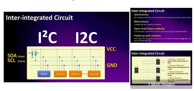
Inter-integrated Circuit pronounced I-squared-C (I²C) or I2C is a two wire bus technology (well actually 4 wires because you also need the VCC and Ground) that is used for communication between multiple processors and sensors.
The two wires are:
* SDA - Serial Data (data line) and
* SCL - Serial Clock (clock line)
Remember, both these lines are 'synchronous' 'bidirectional' 'open-drain' and are 'pulled-up with resistors'.
The I2C bus technology was originally designed by Philips Semiconductors in the early ’80s to allow easy communication between components which reside on the same circuit board.
With I2C, you can connect multiple slaves to a single master (like SPI) or you can have multiple masters controlling single, or multiple slaves. Both masters and slaves can transmit and receive data. So, a device on I2C bus can be in one of these four states:
* Master transmit – master node is sending data to a slave
* Master receive – master node is receiving data from a slave
* Slave transmit – slave node is sending data to the master
* Slave receive – slave node is receiving data from the master
I2C is a 'short distance' 'serial communication protocol', so data is transferred 'bit-by-bit' along the single wire or the SDA line. The output of bits is synchronized to the sampling of bits by a clock signal 'shared' between the master and the slave. The clock signal is always controlled by the master. The Master generates the clock and initiates communication with slaves.
So, to sum it up>
Number of Wires used: 2
Synchronous or Asynchronous: Synchronous
Serial or Parallel: Serial
Clock Signal controlled by: Master Node
Voltages used: +5 V or +3.3 V
Maximum number of Masters: Unlimited
Maximum number of Slaves: 1008
Maximum Speed: Standard Mode = 100kbps
Fast Mode = 400kbps
High Speed Mode = 3.4 Mbps
Ultra Fast Mode = 5 Mbps
TCA9548A I2C Multiplexer Module
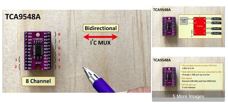
TCA9548A is an eight-channel (bidirectional) I2C multiplexer which allows eight separate I2C devices to be controlled by a single host I2C bus. You just need to wire up the I2C sensors to the SCn / SDn multiplexed buses. For example, if eight identical OLED displays are needed in an application, one of each display can be connected at each of these channels: 0-7.
The Multiplexer connects to VIN, GND, SDA and SCL lines of the micro-controller. The breakout board accepts VIN from 1.65v to 5.5v. Both input SDA and SCL lines are connected to VCC through a 10K pull-up resistor (The size of the pull-up resistor is determined by the amount of capacitance on the I2C lines). The multiplexer supports both normal (100 kHz) and fast (400 kHz) I2C protocols. All I/O pins of TCA9548A are 5-volt tolerant and can also be used to translate from high to low or low to high voltages.
It is a good idea to put pull-up resistors on all channels of TCA9548A, even if the voltages are the same. The reason for this is because of the internal NMOS switch. It does not transmit high voltage very well, on the other hand it does transmits low voltages very well. The TCA9548A may also be used for Voltage Translation, allowing the use of different bus voltages on each SCn/SDn pair such that 1.8-V, 2.5-V, or 3.3-V parts can communicate with 5-V parts. This is achieved by using external pull-up resistors to pull the bus up to the desired voltage for the master and each slave channel.
If the micro-controller detects a bus conflict or other improper operation the TCA9548A can be reset via asserting a low to the RESET pin.
TCA9548 allows a single micro-controller to communicate with up to '64 sensors' all with the same or different I2C address by assigning a unique channel to each sensor slave sub-bus.
When we talk about sending data over 2 wires to multiple devices we then need a way to address them. Its same as the postman coming on a single road and dropping the mail packets to different houses because they have different addresses written on them.
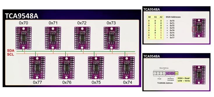
You could have at the max 8 of these multiplexers connected together on 0x70-0x77 addresses in order to control 64 of the same I2C addressed parts. By connecting the three address bits A0, A1 and A2 to VIN you can get different combination of the addresses. This is how an address byte of the TCA9548A looks like. First 7-bits combine to form the slave address. The last bit of the slave address defines the operation (read or write) to be performed. When it is high (1), a read is selected, while a low (0) selects a write operation.
How the Master Sends & Receives Data
A bus is considered idle if both SDA and SCL lines are high after a STOP condition.
The following is the general procedure for a master to access a slave device:
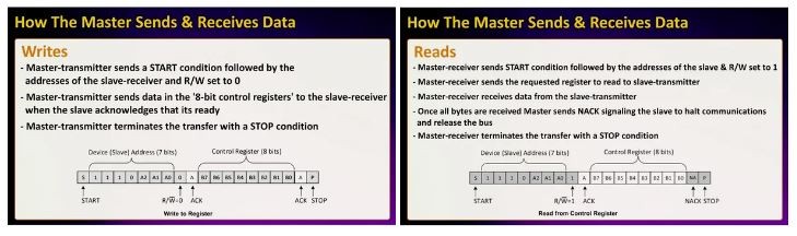
1. If a master wants to send data to a slave (WRITES):
– Master-transmitter sends a START condition followed by the addresses of the slave-receiver and R/W set to 0
– Master-transmitter sends data in the '8-bit control registers' to the slave-receiver when the slave acknowledges that its ready
– Master-transmitter terminates the transfer with a STOP condition
2. If a master wants to receive or read data from a slave (READS):
– Master-receiver sends a START condition followed by the addresses of the slave-receiver and R/W set to 1
– Master-receiver sends the requested register to read to slave-transmitter
– Master-receiver receives data from the slave-transmitter
- Once all bytes are received Master sends NACK signaling to the slave to halt communications and release the bus
- Master-receiver terminates the transfer with a STOP condition
Code

Now, Int the code lets start by including the "Wire" library and by defining the multiplexers address.
#include "Wire.h"
#include "U8glib.h"
#define MUX_Address 0x70 // TCA9548A Encoders address
Then we need to select the port we want to communicate to and send the data on it using this function:
void selectI2CChannels(uint8_t i) {
if (i > 7) return;
Wire.beginTransmission(MUX_Address);
Wire.write(1 << i);
Wire.endTransmission();
}
Next we will initialize the display in the setup section by calling "u8g.begin();" for each display attached to the MUX "tcaselect(i);"
Once initialized, we can then do whatever we want just by calling the function "tcaselect(i);" where "i" is the value of the multiplexed bus and then sending the data and clock accordingly.
I2C Scanner

Just in case if you are not sure about the device address of your I2C shield, then run the attached 'I2C Scanner' code to find the hex address of your device. When loaded to an Arduino, the sketch will scan the I2C network, showing the addresses that are responding.
Wiring and Demo
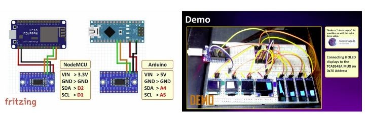
Now, lets check out this quick demo in which I have connected 8 OLED displays to the TCA9548A Multiplexer. As these displays use I2C communication, they communicate with the Arduino using just 2 pins.
Wiring:
Lets start by connecting the multiplexer to a NodeMCU board. Connect:
VIN to 5V (or 3.3V)
GND to ground
SDA to D2 and
SCL to D1 pins respectively
For an Arduino board connect:
VIN to 5V (or 3.3V)
GND to ground
SDA to A4 and
SCL to A5 pins respectively
Once the MUX is hooked up to the micro-controller, you just need to connect the sensors to the SCn / SDn pairs.
Advantages and Disadvantages

ADVANTAGES
* Communication requires only two bus lines (wires)
* A simple master/slave relationships exist between all components
* No strict baud rate requirements like for instance with RS232, the master generates a bus clock
* Hardware is less complicated than UARTs
* Supports multiple masters and multiple slaves
* ACK/NACK bit gives confirmation that each frame is successfully transferred
* I2C is a 'true multi-master bus' providing arbitration and collision detection
* Each device connected to the bus is software-addressable by a unique address
* Most I2C devices can communicate at 100kHz or 400kHz
* I²C is appropriate for peripherals where simplicity and low manufacturing cost are more important than speed
* Well known and widely used protocol
DISADVANTAGES
* Slower data transfer rate than SPI
* The size of the data frame is limited to 8 bits
* More complicated hardware needed to implement than the SPI technology
Thanks
Code
Credits
Related products


Leave your feedback...