

Supersmart Autonomous Car (nxp Cup 2020)
Made by RAACar / 3D Printing / Automotive / Robotics / Sensors / Vehicles
About the project
Badass robot car developed by reasonably advanced monkeys
Project info
Difficulty: Difficult
Platforms: NXP
Estimated time: 6 months
License: GNU General Public License, version 3 or later (GPL3+)
Items used in this project
Hardware components


View all
Software apps and online services
Hand tools and fabrication machines
Story
Scope of the project
Building an Autonomous Vehicle in order to participate in the 2020 NXP Cup.
The Challenge
During the Cup the Car has to complete several challenges including:
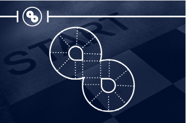
"Figure 8" - a test of precision and reliability
"Speed Limit" - recognizing zones and adjusting its velocity accordingly

"Obstacle Avoidance"
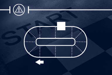
"Emergency Brake"
and the Timed Race in which the Car has to, by itself, navigate through an unknown course. In order to accomplish all these tasks the car is equipped with a variety of sensors which are being monitored and processed by two NXP development boards.
Team "RASCar"
We are two students from the University of Lübeck currently enrolled in the third semester of our bachelors’ program in Robotics and Autonomous Systems (RAS), hence the name “RASCar”.
Development Process
As we have participated in last year’s NXP Cup, we already had a reasonably solid Codebase for the project. Due to the more relaxed rules this year and experiences from last year there is still the potential for several improvements to be made, however.
Vague Timeline of last year’s development process:
22.02.2019: Assembly of Alamak car kit, driver installation, realization that car is smarter than us
23.02.2019: Updated bootloader, change of development environment, first blink sketch
24.02.2019: Tests with supplied TFC libraries, car moves now
26.02.2019: Abandoning of the libraries and switching from code warrior to mbed also decision to start from scratch for improved performance
30.02.2019: All core components needed for driving rewritten and improved (for example exposure setting for image capture, servo control and motor control)
31.02.2019: Controller design, line recognition algorithm, death of servo motor
01.03.2019: Added external BEC for clean power for servo
02.03.2019: Algorithm semi-reliably finds lines, Controller in desperate need of tuning, problems with track illumination
03.03.2019: Addition of RPM sensors
04.03.2019: Lighting issues solved with more light, new linear digital Servo, suddenly improved performance, car can now drive in reverse
06.04.2019: Improvements to line recognition and classification; car does not notice if line passes over center point of image
07.04.2019: Significant improvements to image data processing, implementation of canny edge detection
13.03.2019: Tests with auto exposure, car slows down for curves and speeds up on straight line
16.03.2019: Experiments with automatic PID tuning result in the car taking up flight and (luckily) only cracking the mast
17.03.2019: Automatic PID tuning has been abandoned for manual tuning
18.03.2019: Improvements to overall execution time and number of images processed each second
19.03.2019: Line detection now solid in most lighting conditions (also car can drift now which looks really cool in slow motion)
24.03.2019: Active steering implemented by having inner wheels in turns be slower than outer wheels
25.03.2019: Stop line and speed zone recognition implemented
26.03.2019: Last efforts in implementing Ultrasonic Sensors, fine tuning the Controller and the drive to Munich
27.03.2019: NXP Cup 2019
Timeline of the development during the new season:
10.06.2019: Improved RPM sensors with custom disks for rear axle
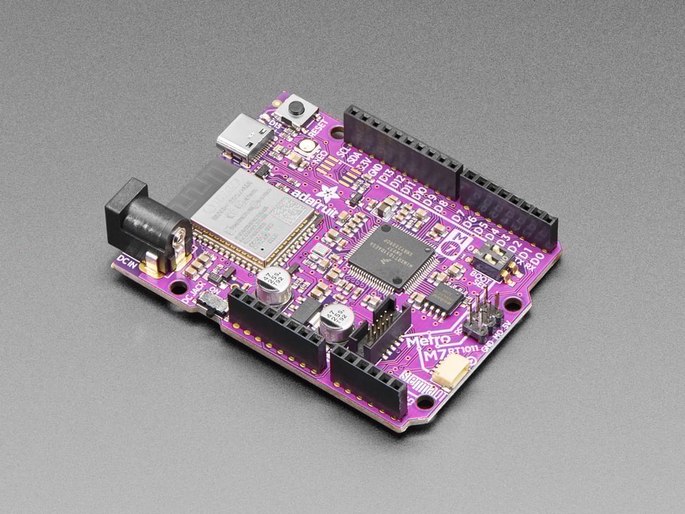
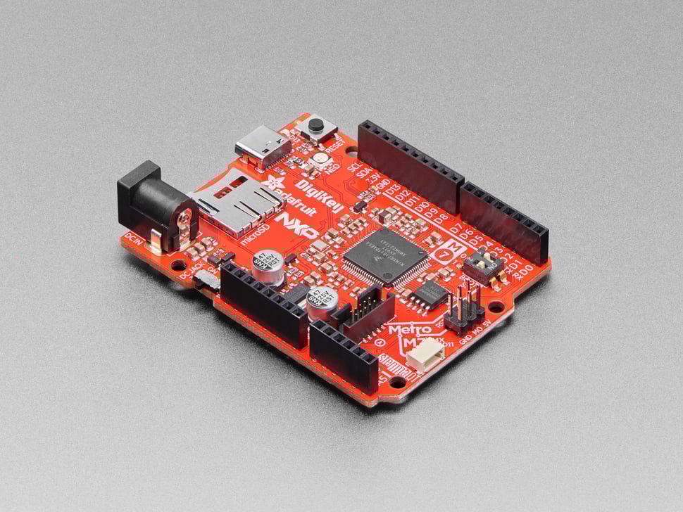
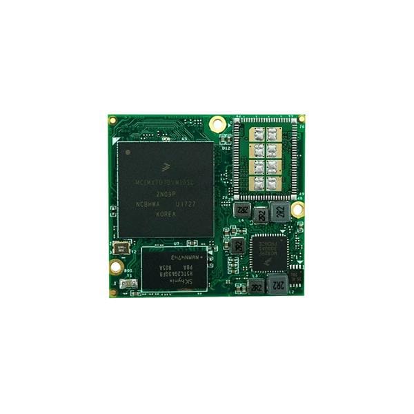
Late 2019: We started by designing our PCB as we wanted to use two processors instead of just one, order of K66F board as primary MCU, plans for software structure and hardware improvements.
01.12.2019: Arrival of Pixy 2 camera, ported Arduino Pixy 2 library to mbed
2019/2020: Arrival of custom PCB, improvements to hardware with the addition of Ultrasonic Sensors, buttons, BEC for power
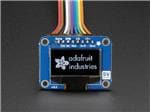
22.02.2020: Addition of OLED screen and IO-Spoiler
26.02.2020: Implementation of components, communication between the two boards
27.02.2020: Addition of rotary encoder and menu/mode selection system when car is started
29.02.2020: Ultrasonic Sensor wiring, testing and Emergency Brake testing
01.03.2020: Disassembling everything and switch to brushless car kit
03.03.2020: Brushless car kit functional, addition of brushless RPM sensors, PID controller and tuning for motor speed
04.03.2020: Addition of IR-Sensors on the underside of the car for improved stop line recognition
05.03.2020: Speed Zone detection and obstacle avoidance
06.03.2020: Inaccuracy in steering is becoming a problem; complete disassembly and rework of steering geometry
07.03.2020: New Lightbar and experiments with dual CCD cameras
10.03.2020: Controller tuning and evaluation of new approach to steering control
14.03.2020: Fine tuning controller, speed settings, vehicle speed is now acquired
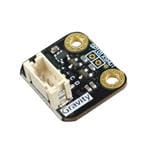
30.03.2020: New TOF Distance Sensor implemented
03.04.2020: Bracket for new Sensor and new Bumper for Ultrasonic Sensors designed
10.04.2020: New Parts printed, and sensor array assembled
12.04.2020: Re-Printed some parts with overhauled design (bigger cable box, IO-Spoiler)
15.04.2020: New design of LED Lightbar, now with sturdier construction
20.04.2020: New approach to image processing of Pixy 2 camera data
26.04.2020: Testing of all the driving modes, controller tuning
Hardware/Software Architecture
To get the most possible control over our car, we, for the most part, wrote custom libraries for all the essential driving related components.
The Hard- and Software are decoupled into Sensor/IO-Layer (K66F) and Driving/ESC-Layer (KL25Z). This allows for faster processing of real time data and better separation between functionality. We furthermore had a number of improvements in mind which required more IO pins than a single processor would offer.
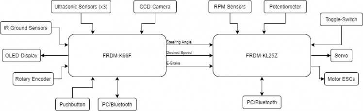
This means that the K66F MCU gathers and processes the Sensor and Input Data according to the user selected mode, reports telemetry regarding the vehicle’s surroundings back to the user and sends only the necessary information to the KL25Z board. The KL25Z is therefore free to constantly update and adjust motor RPM and set the Servo position according to the data provided by the K66F board while also monitoring slip, oversteer, understeer and other driving parameters based on measured RPM, the curvature of the road (servo angle) and the use of its gyroscope. It thus functions as the Electronic stability control (ESC) system of the vehicle by using sensor fusion for computing a real time model for detecting, predicting and ultimately eliminating undesired behavior in the car. A more detailed description can be found further down.
1. Changes to the stock car
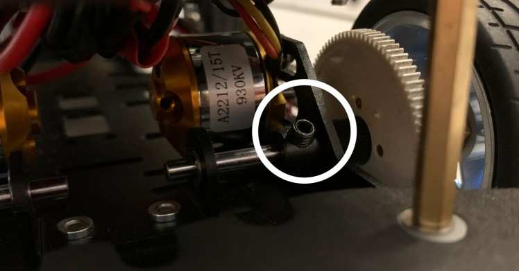
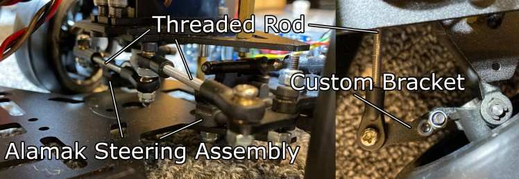
Some small changes were made to the stock configuration of the brushless car kit including small additional holes for mounting some of the 3D printed parts, the front bumper was exchanged for the bracket for the ultrasonic distance sensors. Also, the entire front steering assembly has been replaced by retrofitting the old Alamak steering system with additional 3D printed linkages and some custom length threaded rod. Furthermore, we had to shorten a screw provided in the kit that prevents the axle from sliding in its two bearings and slightly hitting the motors each revolution:
2. Power Supply
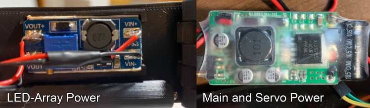
During testing it was noted that even slight instability in the power supply system led to overall undesirable behavior in the vehicle. So, when the stock power supply fried our first servo motor, we switched to two BECs for power, one for the servo and a separate one for all the other components as spikes in the servo power led to glitches elsewhere. Furthermore, the LEDs get their own power directly from the Lipo which is then fed through a step-up module as they require 9V instead of the 5V needed by the rest of the components.
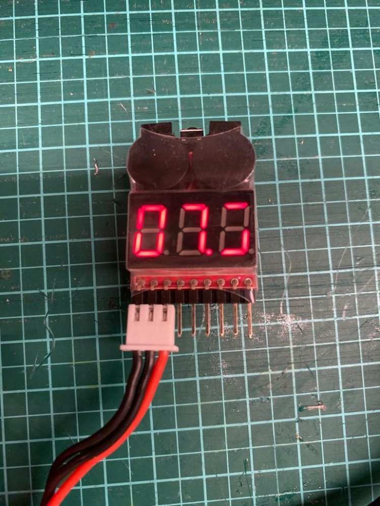
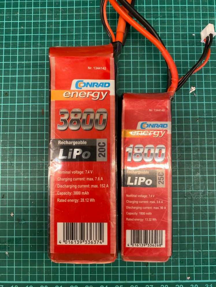
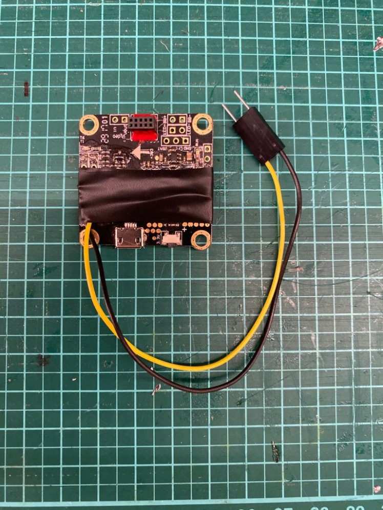
Instead of using NiMh bateries like last year, we decided on using LiPo batteries, which are able to accomodate more capacity in less space and providing much more current, reducing spikes in the supply if for example the servo motor makes a quick turn or the motors start turning. Since we are aware of the potential danger of the batteries if handled unproperly we equipped them with so called LiPo checkers that make a loud buzzing sound if the voltage drops below a certain value, so we can quickly recharge them to a safe level.
3. Image Capture and Processing
For following the track, the camera Image must be read from the CCD Sensors and processed. During testing we found that it is beneficial to be able to control the camera exposure time, as lighting cannot be presumed constant in all possible environments. Thus, we decided to implement an exposure configuration screen during the car’s startup procedure. This however also means that the framerate obtained by the camera changes with differences in lighting, to combat this fact, an array of LED Lights was added to the car to ensure descent track illumination under all driving conditions. This also mitigates the effect of AC lights lighting the track causing pulsation in the image as our DC LED array is brighter in the part of the track we process.
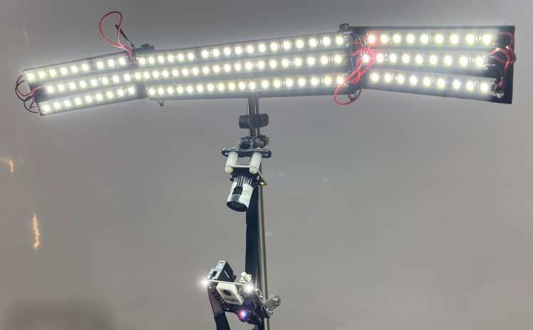
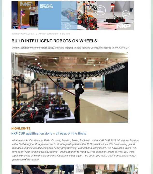
(Also as we made it into the newsletter after last years qualifying, we felt like we have to defend out title of "biggest LED banana")
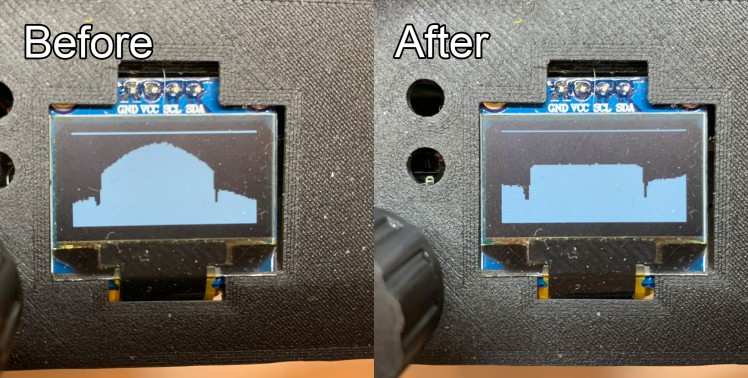
When reading the image from the CCD sensor, first the data is scaled because the CCD camera tends to deliver an image that is brighter in the middle and then falls off in brightness to either side. To mitigate this effect, we calibrated the camera while looking at a white flat surface and then calculated the constant factors by which to scale the individual brightness values. This map of constant factors can then be stored in memory and applied every time an image is captured:
- //read pixel and transform based in constant compensation map
- rawData[i] = cameraIn.read_u16() * cam_exposure_compensation_map[i];
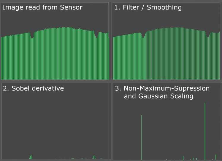
After the image data is obtained by the camera, it must be processed. In general, a two-dimensional approach to canny edge detection was used. For this, first a light gaussian blur is applied to the image in order to remove noise, then a Sobel Operator is applied for finding differences in the image (i.e. the black line indicating the track) and at last a gaussian distribution and non-maximum-suppression are applied leaving in most cases only the lines in the picture.
After the image processing finishes, our algorithm finds the lines in the image while also taking the possibility of a line passing over the center of the image into account. This yields reasonably solid line data; it was however also found that a plausibility check after the processing eliminated previous problems of sudden movements due to faulty readings.
Image processing:
- float smooth[128];
- float sobel[128];
- int imageDataProcessing(int dataIn[]) {
- //image data smoothing------------------------------------------------------------------
- dataIn[0] = (dataIn[0] * 2 + dataIn[1])/3;
- dataIn[127] = (dataIn[127] * 2 + dataIn[126])/3;
- for (int i = 1; i < 127; i++) {
- dataIn[i] = (dataIn[i-1] + 2*dataIn[i] + dataIn[i+1])/4;
- }
- //sobel operator-------------------------------------------------------------------------
- for (int i = 1; i < 126; i++) {
- sobel[i] = abs(dataIn[i-1] - dataIn[i+1]);
- }
- //non-maximum supression-----------------------------------------------------------------
- for (int i = 1; i < 127; i++) {
- if ((sobel[i] > sobel[i-1]) && (sobel[i] > sobel[i+1])) {
- if (sobel[i] >= 0) {
- sobel[i] = sobel[i];
- } else {
- sobel[i] = 0;
- }
- } else {
- sobel[i] = 0;
- }
- }
- //gaussian scaling-------------------------------------------------------------------------
- //...
- return *sobel;
- }
With reasonable exposure settings, around 90-130 pictures are processed each second. We are currently also exploring the option of using two CCD cameras, one with a shorter view distance and one with a longer. As we can read both cameras simultaneously, there is no performance hit when using more than one camera. For now, we are only using one CCD camera and the pixy camera though, as the contacts on one of the flat ribbon cables broke off and we could not find a replacement in the correct length yet.
4. Pixy 2
When designing the PCB, we also included a header for the Pixy 2 camera. For connecting the camera, we decided to use SPI as it is faster than I2C. We then ported the Arduino Pixy2 library for use in our project. After gathering the line data from the pixy camera, we apply some processing to make it easier to interpret the results obtained.
- #ifndef POINT_H
- #define POINT_H
- static const float HMatrix1[3] = {0.028047117269050, 0.019262884992415, -0.809041169681449};
- static const float HMatrix2[3] = {0, 0.041981495880462, -0.585243901679298};
- static const float HMatrix3[3] = {0, 0.000557375144456, 0.004637361201878};
- class Point {
- private:
- float x, y;
- public:
- Point(int xValue, int yValue) {
- x = (float)xValue;
- y = (float)yValue;
- }
- int getX() {
- return (int)floor(x);
- }
- int getY() {
- return (int)floor(y);
- }
- void transform() {
- float vx,vy,vz;
- vx = HMatrix1[0] * x + HMatrix1[1] * y + HMatrix1[2];
- vy = HMatrix2[0] * x + HMatrix2[1] * y + HMatrix2[2];
- vz = HMatrix3[0] * x + HMatrix3[1] * y + HMatrix3[2];
- x = vx / vz;
- y = vy / vz;
- }
- };
- #endif
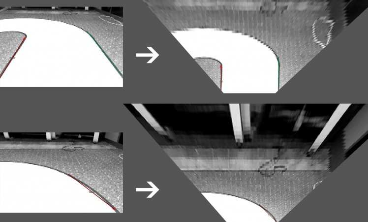
First, we apply a homography matrix to the vectors to scale them into a birds eye view:
Then, the angle of the track is determined, this is then fused with data obtained from the linescan camera and an angle correcting the error/misalignment of the car regarding the set point is determined and applied to the servo motor.
The road Angle Θ is calculated from the vector obtained by the camera:
- float getRoadAngle() {
- //pixy new reading
- pixy.line.getAllFeatures();
- //delete old points
- delete one;
- delete two;
- if(pixy.line.numVectors >= 1) {
- //if pixy has vector
- one = new Point(pixy.line.vectors[0].m_x0, pixy.line.vectors[0].m_y0);
- two = new Point(pixy.line.vectors[0].m_x1, pixy.line.vectors[0].m_y1);
- //transform the valid points according to H matrix
- one->transform();
- two->transform();
- } else {
- one = new Point(0,0);
- two = new Point(0,0);
- }
- if(one->getX() >= 0 && one->getY() >= 0 && two->getX() >= 0 && two->getY() >= 0) {
- //if the reading is valid
- if ((one->getX() != 0 || one->getY() != 0) && (two->getX() != 0 || two->getY() != 0)) {
- //calculate the current angle of the track from the vector
- roadAngle = atan2((float)one->getX() - two->getX(), (float)abs(one->getY() - two->getY()));
- }
- } else {
- roadAngle = 0;
- }
- return roadAngle;
- }
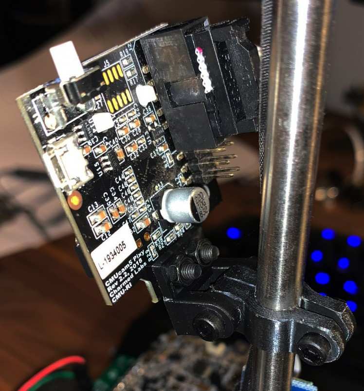
The Camera is mounted with a custom bracket and cable:
5. Controller Design
After finding and classifying the outline of the track and the current track angle, a steering angle must be calculated. This is accomplished by calculating the curvature of the track from the change in line position and the deviation in center point of the image/track from the current position of the car. The controller hereby tries to calculate the angle in such a way that the center point between the two lines matches a given set point which is the center of the image for straight segments of the track and left or right of the center for turns. If only one line is visible, an alternative line is calculated from the track width. Flexibility in changing the desired setpoint allows for an easy implementation of the obstacle avoidance challenge and better cornering speeds.
- //if we are not currently avoiding an obstacle
- if (!isAvoiding) {
- if (hasleftLine && hasrightLine) {
- //if both lines are present, drive in center
- setPoint = 64;
- } else if (hasleftLine && !hasrightLine){
- //right curve, move set Point to left
- offset = (currentSpeed*20 <= 40) ? currentSpeed*10 : 40;
- setPoint = (int)((float)(64 - offset));
- } else {
- //left curve, move set Point to right
- offset = (currentSpeed*20 <= 40) ? currentSpeed*10 : 40;
- setPoint = (int)((float)(64 + offset));
- }
- }
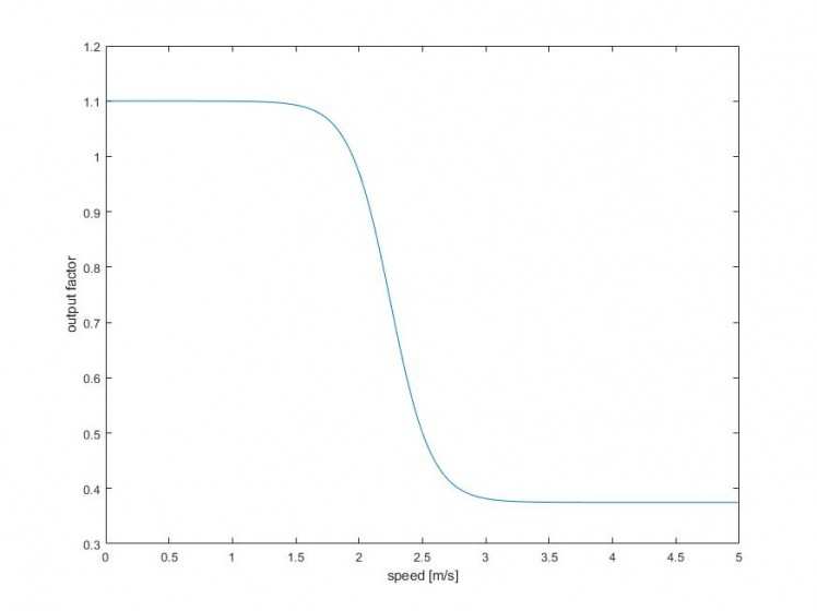
After calculating the angle to correct for the error, the result is scaled based on the speed of the vehicle. This is done because during higher speeds the steering response does not need to as aggressive as during slower speeds.
- //set the servo position
- servo.setAngle(90 - (0.725358/(1+0.000000951059*exp(6.17221*calcPID(roadAngle)))+0.374759));
Several different approaches in the implementation of the Steering control have been undertaken and it has been found that a Stanley controller or a simple PD controller with careful tuning yield the most desirable results. Ultimately we ended up with a combination of both and so far we are reasonably happy with the results we are getting so that now we can concentrate on tuning and tweaking the controller in order to achieve higher speeds.
Calculating the correction:
- float calcPID(float roadAngle) {
- //get the current car position from left and right line
- isValue = (currentLines.getRight() + currentLines.getLeft()) / 2;
- //calculate the error / deviation from set point
- PID_last_error = PID_error;
- PID_error = setPoint - isValue;
- //calculate correction value to correct for error
- correction = Kp * PID_error + Kd * (( PID_error - PID_last_error ) / (dt.read_ms() )) + Ka * sin(roadAngle)*180/3.141592;
- //reset timer
- dt.start();
- dt.reset();
- return correction;
- }
6. IR-Ground Effect Sensors
During testing it was noticed that purely relying on the camera for stop line detection was prone to error as this largely depends on passing over the line straight on. Also, during testing with a variety of speeds, it appeared beneficial for the car to also stop when passing the outline of the track and thus refraining from slamming into the wall at high velocity.
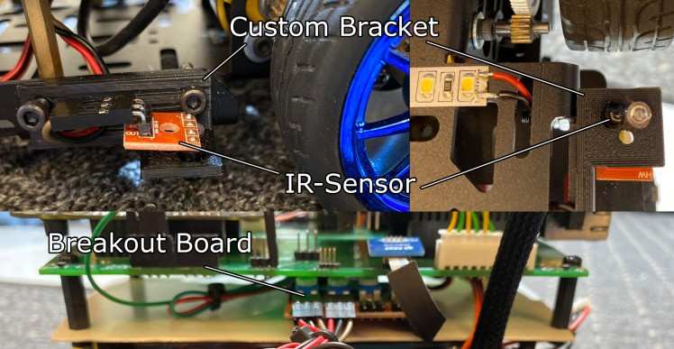
Thus, IR-Sensors were added to the underside of the car with 3D printed brackets which trigger an interrupt when they pass over a black line. If the time between the two sensors being triggered is less than 10ms, the brakes are applied, and the car comes to a stop:
- //Interrupt service routine for left IR Sensor
- void groundLeftISR() {
- if (groundDetectionDebounce.read_ms() > 0 && groundDetectionDebounce.read_ms() < 10 && rightGroundDetected) {
- //if other sensor has already triggered, brake
- eBrake = 1;
- } else if (groundDetectionDebounce.read_ms() == 0 && !rightGroundDetected) {
- //if this sensor is first to trigger, start timer and set var
- groundDetectionDebounce.start();
- leftGroundDetected = true;
- }
- }
- //Interrupt service routine for right IR Sensor
- void groundRightISR() {
- if (groundDetectionDebounce.read_ms() > 0 && groundDetectionDebounce.read_ms() < 10 && leftGroundDetected) {
- //if other sensor has already triggered, brake
- eBrake = 1;
- } else if (groundDetectionDebounce.read_ms() == 0 && !rightGroundDetected) {
- //if this sensor is first to trigger, start timer and set var
- groundDetectionDebounce.start();
- rightGroundDetected = true;
- }
- }
"eBrake" in turn triggers an interrupt on the KL25Z board, immediately halting the motors so that the car comes to a stop. The brake can be released by pressing the green Button in the IO-Spoiler.
If the timer is running it is reset every 10ms:
- if (groundDetectionDebounce.read_ms() > 10) {
- //if more than 10 ms, timeout and reset
- groundDetectionDebounce.stop();
- groundDetectionDebounce.reset();
- leftGroundDetected = false;
- rightGroundDetected = false;
- }
Sensors trigger when passing the outline of the track or the stop line:
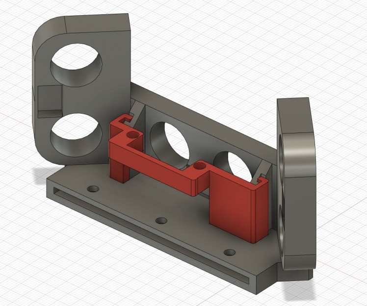
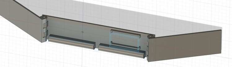
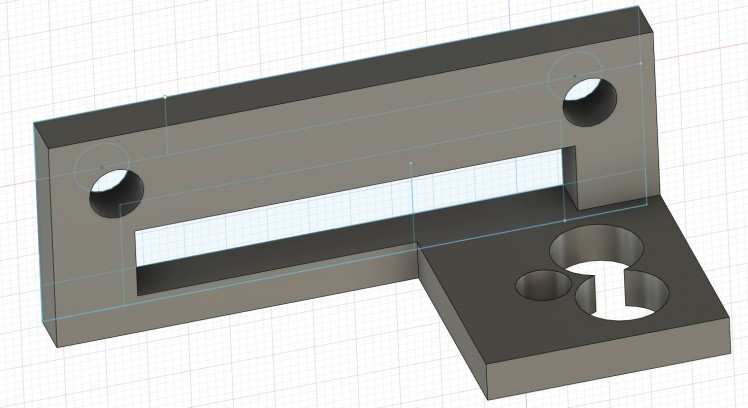
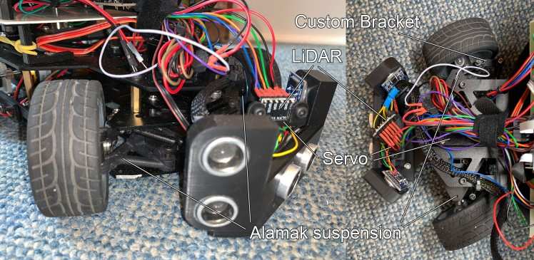
7. Distance Sensors
In order to successfully complete the emergency braking and the obstacle avoidance challenges, additional distance sensors are required. As we already had several HC-SR04 Ultrasonic Distance Sensors from previous projects and found them to be rather reliable, a From Bumper housing three Ultrasonic Sensors was implemented.
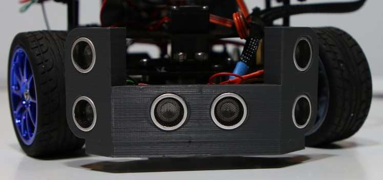
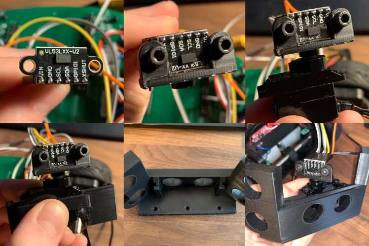
However, during testing it has been found that objects on the track could not always be recognized with the ultrasonic sensors as the accuracy declines rapidly at angles above 30°. As they do however reliably recognize obstacles straight in front of the vehicle, we did not want to significantly change their layout as they work well for the emergency braking challenge. For obstacle avoidance a different type of sensor is needed though. For this we chose the VL53L0X Time-of-Flight laser-ranging sensor as it was cheaper than other LiDAR solutions and with a range of 2m sufficient for our application. In order to integrate the sensor, a rail system has been added to the ultrasonic sensor mount to easily attach and detach the servo bracket.
8. Steering Geometry
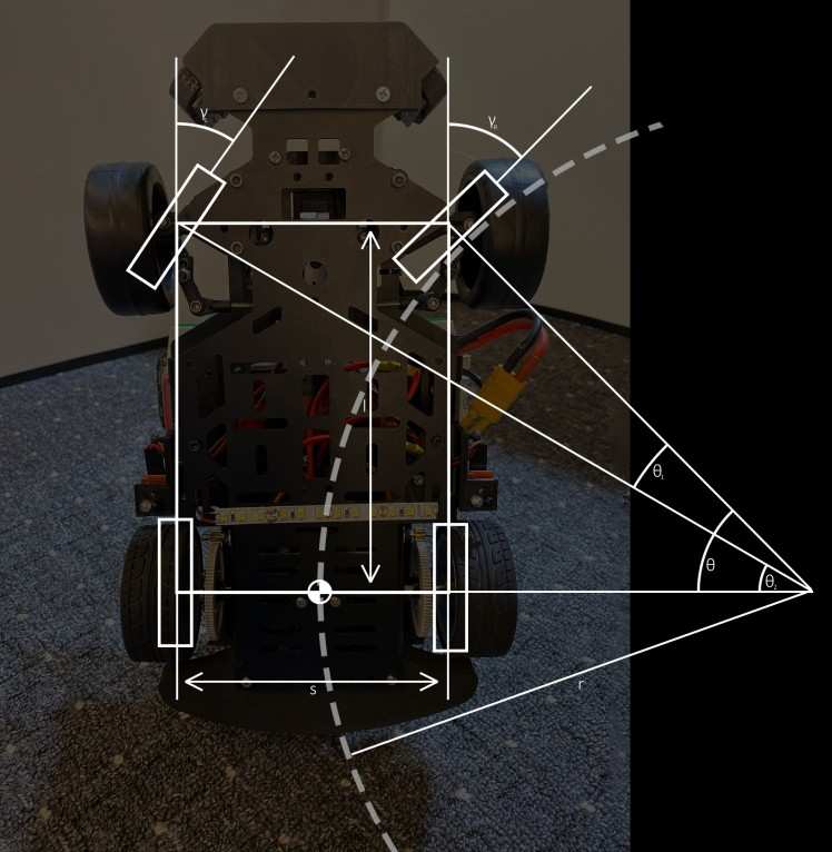
It has been found that the stock steering system featured in the DFRobot Brushless car kit tends to be imprecise in as far as there is a significant variation between the maximum possible cornering radius of a left and a right turn. As the brushless car kit does not feature any sort of adjustments like adjustable rods to alter the toe-angle or especially a way to variate the trailing rate which is rather important to assure a good return to center leading to a stable forward movement which has significant effects in crossing the intersections. For remedying this, the steering assembly of the alamak car kit has been retrofitted to the car. In doing so there are a few more possibilities to fine tune the steering, reducing the need of correcting inconsistencies in software such as the camber, toe rate or even the trailing rate. Also, the steering geometry has been changed to closely follow the Ackermann steering geometry preventing any slippage in cornering which again leads to less work for the controller to counteract the undesired behavior.

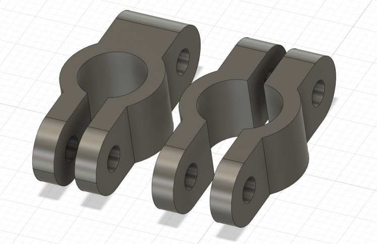
For achieving this, all necessary car parameters have been measured and new brackets for the front wheels have been designed in such a way that, if they were extended, they would meet exactly at the center point of the rear axle resulting in an almost perfect path for each wheel while cornering. They were 3D printed and are attached to the servo with custom length threaded rod. Furthermore, the linkages connecting the newly designed brackets and threaded rod together were taken from an RC car due to the old ones not featuring any kind of bearing and therefore leading to more stress and reduced reaction time in the servo motor.
9. Motor Control and Speed Control
Retrospective:
While examining last year’s rules of the NXP cup we came upon a section mentioning a bump in the track which led to two things we had to assure for successfully surpassing this obstacle. The first problem lies in the main camera losing its vision over the track at a certain point, but the second and by more important thing we had to consider was speed control. As with too much power applied to the motors a surpassing was possible, however the downhill section became a major problem due to the speed gained that a simple curve behind the bump would lead to the car not being able to make the turn due its significant gain in speed.
Thus, to solve this problem we added RPM sensors based on two hall effect sensor and a magnet on each spur gear, on the software side we settled on a simple PI-controller to regulate our RPM instead of the motor power. This brought with it the desirable side-effect of being able to test the car with constant speed during all our test runs and thus making the tuning of the PID controller for steering much easier.
From now on:
For this year's Cup we decided on switching to the new DMF car kit and with that changing our motors from a brushed DC type to a brushless AC type. With that, a change in RPM sensors was needed as the old one's only had a low resolution of just eight measurements every wheel rotation.
With the fact of having an alternating field in the three phases AC current we decided to aim for RPM sensors that precisely measure the times per second that the phases cross each other thus resulting in a far better resolution and latency between reports.
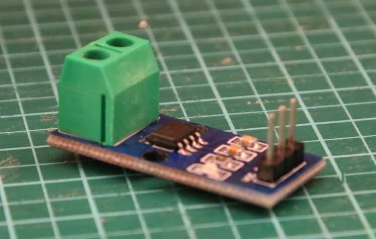
Additionally we added two current sesnors to each of the ESCs to detect slippage of the at quick changes of the speed like for example at the start or accelerating on the straights. If for example the current decreases while the car has given order to accelerate the power was obviously too much and therefore the wheels start slipping and the current decreases. The sensors works by outputting 100mV for each Ampere of current flowing and relys on a hall effect sensor mesauring the electrical field.
On the controller side we stuck with a simple PI controller but this time with far fewer oscillations and greater accuracy.
In the beginning we did the PI calculations on the KL25Z board which meant a lot of Interrupts and thus decreasing our computational power. But after making some research on the provided ESC controller we discovered that they are able to do those calculations on them. This requires a programming device which we acquired from a multicopter and a firmware version below 15 . Once the feature is activated a PWM signal between 1000 and 2000 Us results in an setSpeed of 0 to 50.000RPM which the ESC with provided parameters P and I tries to reach.
Torque Vectoring:
Instead of simply applying an offset to the outer wheel in corners we decided to implement full torque vectoring this time, our steering geometry calculations were a great starting point delivering the exact cornering radius for a given servo position, with the ability of dialing in the exact RPM desired for each wheel, this resulted in far more stable cornering.
- //torque vectoring______________________________________________________
- steeringRadius = calcTurningRadius(steeeringAngle)
- //car desires a left turn
- if(steeringAngle < 1500){
- //calculation the deviation from the center point of rear axle around the turning point
- TV_left = steeringRadius / 100 * ( steeringRadius + leftRearTireOffset ) * ESP_gain;
- TV_right = steeringRadius / 100 * ( steeringRadius + (rightRearTireOffset * (-1)) ) * ESP_gain;
- }
- //car desires a right turn
- else if (steeringAngle > 1500){
- TV_left = steeringRadius / 100 * ( steeringRadius + leftRearTireOffset * (-1) ) * ESP_gain;
- TV_right = steeringRadius / 100 * ( steeringRadius + (rightRearTireOffset ) ) * ESP_gain;
- }
- //____________________________________________________________________
- //behaviour arbitration______________________________________________________
- //determine whether ESP intervention is necessary and if it is intervene
- if(isSlipping()){
- //inhibit all other behaviours and let ESP stabilize the car
- //calculate intervention
- ESP();
- //set motor speed
- setMotorSpeed(ESP_left,ESP_right);
- //set servo to stabilize the car only in worst case
- setServo(ESP_servo);
- }
- //if not then proceed with standard torque vectoring
- else{
- //calculate PID controller and set motor speed
- calcPID(desiredSpeed,TV_left,TV_right);
- setMotorSpeed(PIDoutLeft,PIDoutRight);
- }
- //____________________________________________________________________
10. ESP
Even with our big improvements in the design of the speed controller and the steering geometry there are still some situations in which the speed is just too great for the car to make the turn resulting in a loss of traction and therefore leaving the track, or crossing the intersection in a slightly imperfect way thus leading to rapid movement of the steering when correcting back into the desired path which, again, leads to the front wheels loosing traction.
- boolean isSlipping(){
- //retrieveing the desired steering angle from k66 board calculated through our model
- desiredSteeringAngle = getHeadingAngle(steeringAngleK66.pulsewidth_us());
- //retireve accelaration values from the onboard accelerometer directions changed due to mounting
- AccY = getAccX();
- AccY = getAccY();
- //calculate normalized scalar Product between steeringAngle and AccAngle
- scalarProduct = (1*AccY)/ ( (1 + sqrt(AccX*AccX+AccY*AccY) ) );
- //calculate the angle between forward angle and accelerometer angle
- AccAngle = cosh(scalarProduct);
- //slippage is determined by the deviation of the two angles including a threshhold for inaccuracy
- if( AccAngle <= (desiredSteeringAngle-10) || AccAngle >= (desiredSteeringAngle+10) ){
- return true;
- }else{
- return false;
- }
- }
Therefore, the main purpose of the KL25Z board is to function as the ESP of the vehicle and avoiding the effects of the aforementioned situations. To accomplish this task, we use sensor fusion between the two wheel RPM sensors (the speed of the vehicle), the gyroscope, the accelerometer and steering angle to detect and ultimately circumvent undesired behavior such as slip, understeer and oversteer.
For the torque vectoring and the ESP to work properly, we needed the exact cornering radius of the car while driving under optimal road conditions to acquire the optimal heading vector for the car, this is then compared against the data obtained from the accelerometer. With the valid information from the accelerometer it is possible to calculate the deviation from our desired path vector represented by the servo heading. If the deviation is beyond a certain threshold, the vehicle is, based on the sign of the deviation, in an understeer condition which we handle by limiting the motor current while also putting a slight gain on our torque vectoring on the rear axle as that should still have traction, or we are in an oversteer condition, which is handled by also reducing motor power and actively intervening in the servo position, steering in the counter direction of the accelerometers direction vector as the rear axle now has no traction. This is done until both vectors from the accelerometer and the calculations for the steering position are in alignment.
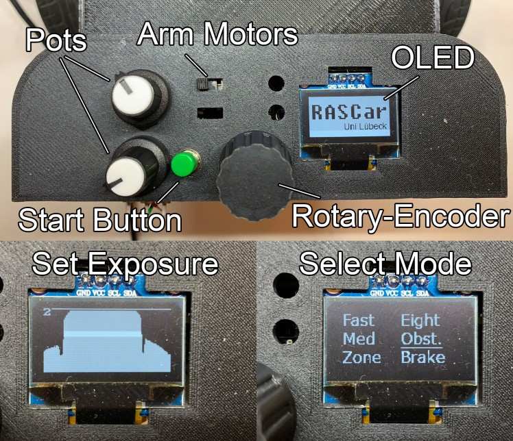
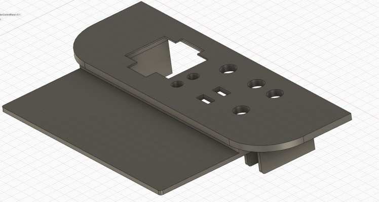
11. IO and Settings
The spoiler houses the IO which can be used to make on-the-fly adjustments to the vehicle mode (Race, Em. Brake, Obstacle, Speed Zone, Eight), the camera exposure and the max speed of the vehicle. The OLED screen furthermore displays relevant information dependent on the currently selected driving mode for debug purposes. IO Components are split between the boards and connected to their respective IO-Headers on the PCB.
Quick Overview of the IO and start-up procedure:
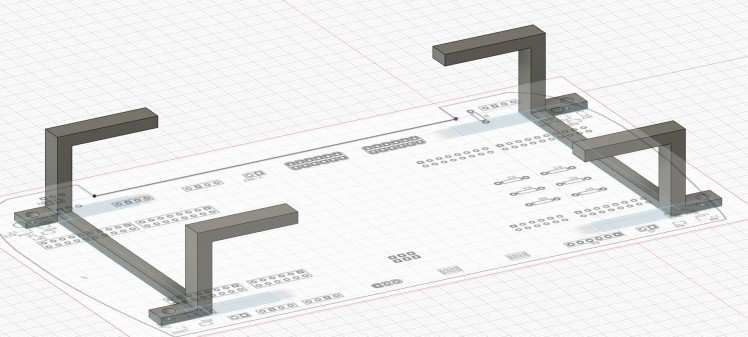
12. Custom PCB
Last year we noticed that we had reached the limit of what was possible with only using the KL25Z board and as we wanted to implement a number of additional features for this year’s challenge, we decided on designing a custom PCB to provide stable connections to all the Sensors, IO-Components and between the two board. It furthermore provides the voltage divider for the Ultrasonic Sensors and four RGB-LEDs of which the front most two can be controlled by the K66F board in order to indicate a left and right line and the ones in the back by the KL25Z board to indicate braking and loss of traction. Also, IO-Headers for the two dev boards were added for easy access to additional pins needed for further expansion.
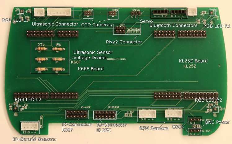
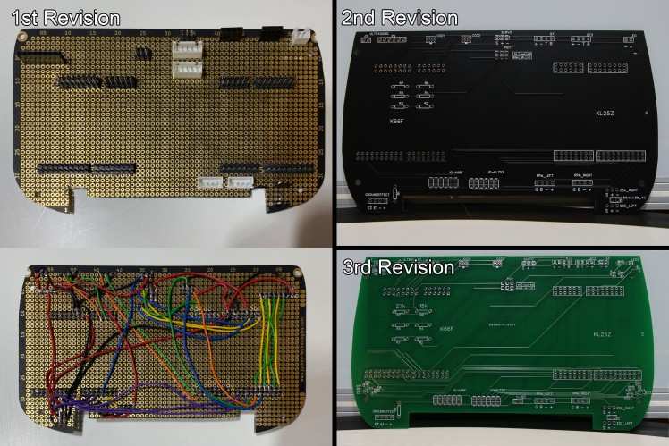
Initially we had planned to design a completely custom PCB but as neither of us had any previous experience with designing or soldering SMD components, we decided against that for now. So, we used EaysEDA for designing the PCB in the shape of the Alamak car and had them manufactured by JLCPCB. Also for the PCB we went through a few iterations:
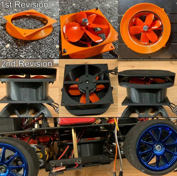
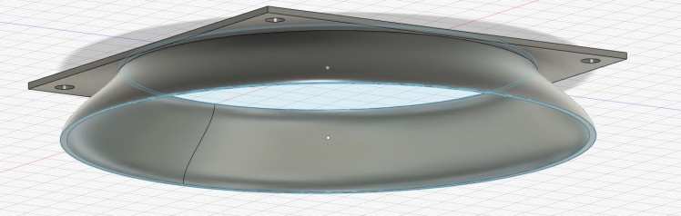
13. Impeller
The reason why we left so much free space in the lower part of our car is that we are planning on adding a custom designed impeller for additional down-force and better cornering speed.
Even though the ESP tries to prevent tire slip, when driving with a high velocity the car might still lose traction especially in tight corners.
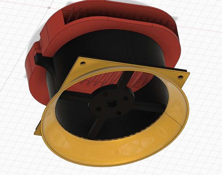
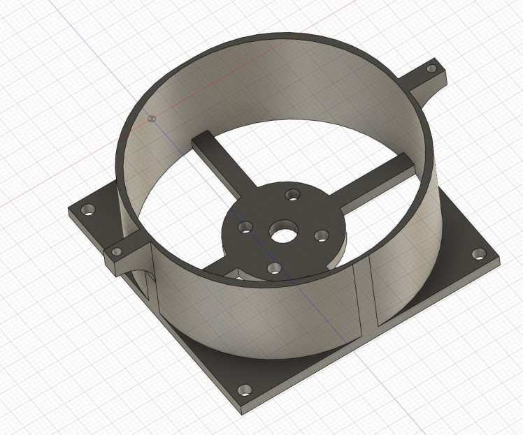
For this to work a fan shroud has been designed and printed that houses a hobbywing 2205 brushless drone motor with a maximum thrust of 1.25kg. As there were no impeller blades available in the desired size, a stack of two shortened drone propellers has been added. The air passes through a funnel at the bottom of the vehicle in order to maximize surface area and getting closer to the ground, the air is then exhausted through a custom designed 3d printed air hood featuring thin air canals in order to minimize turbulence when the air exits on the side of the vehicle.
In order to supply the motor with current a 10A Boost Converter has been added to increase the voltage to about 16 Volts e.g. a 4cell Lipo battery to maximize thrust, it is being cooled by the airflow generated by the impeller, as the air exits from the hood, it passes through the heatsink of the Boost Converter.
For now the Impeller lives in the old Alamak car from which we took the front steering assembly. When we are happy with the design we will be integrating it into our car but as that means cutting a rather significant hole into the bottom panel of our car, we wanted to hold out on that.
We are furthermore investigating the possibility of adding a servo motor for redirecting the air exiting the shroud in order to give the car additional stability while cornering.
But so far it looks rather promissing:
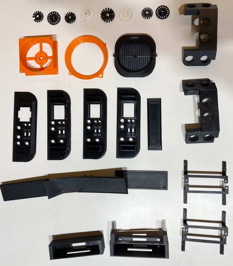
3D Printed Parts
For the design of our car we needed a number of custom parts which we designed in Fusion 360 and printed on our Ender 3 Printer. The following Parts were designed and made by us:
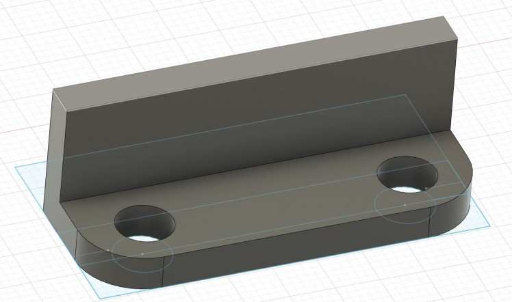
Ultrasonic Sensor Bumper with Servo Bracket for LiDAR Sensor
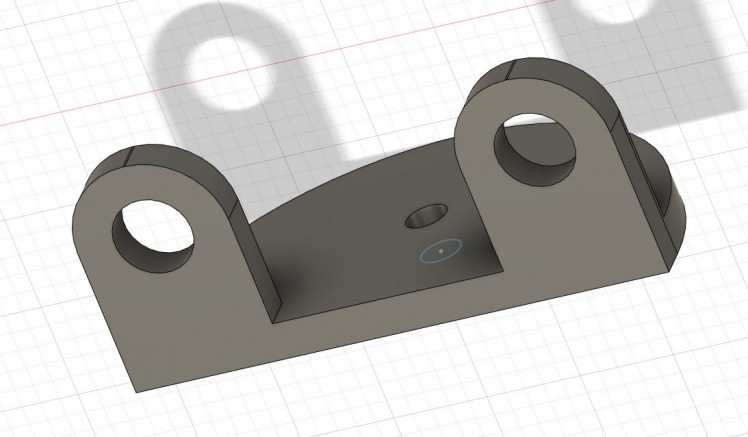
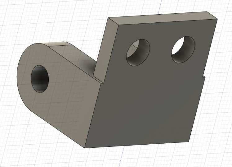
LiDAR Sensor Bracket for Servo Motor
IO-Spoiler
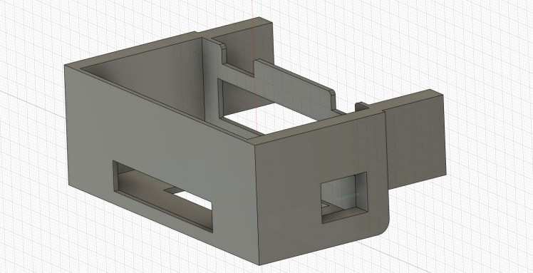
Cable Crate
LED Array
IR-Sensor Brackets
Battery Blocks
PCB Spacers
Rod-Mounts
Pixy 2 Camera Bracket
Impeller Base/Mount for Drone Motor
Impeller Air Hood
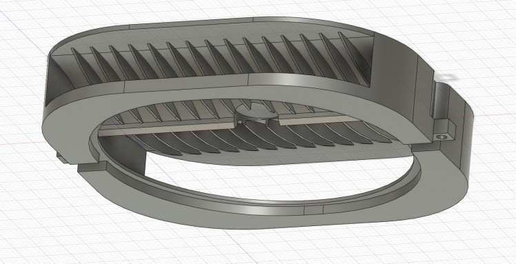
Impeller Underside
As neither of us had any previous experience with designing and manufacturing parts that ultimately need to fit together, we went through a few iterations:
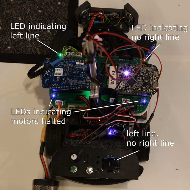
Debugging and Testing
In order to make the testing and debugging process as simple and quick as possible several communication options were implemented including:
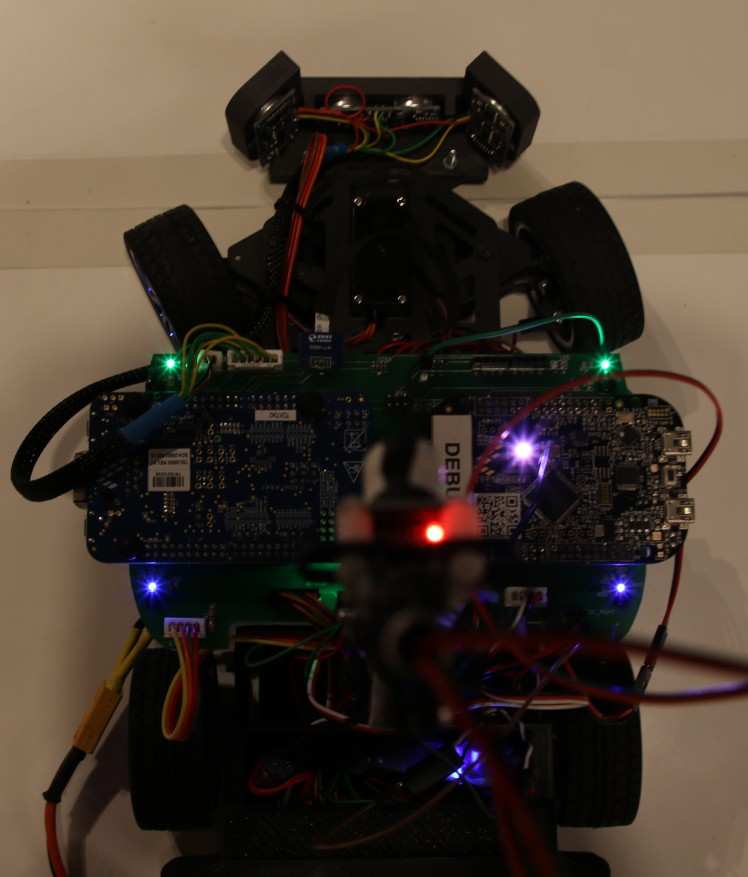
- A total of 6 RGB LEDs, 3 for each DEV board
- Bluetooth serial communication for each board seperately
- OLED screen for displaying the camera image, ultrasonic sensor distances, IR sensor readouts, selected exposure, etc. depending on the user selected mode
- Buttons, switches and two pots for adjusting and switching between functionality
- Processing sketch for displaying two CCD camera images simultaneously and additional information over serial
LEDs and Screen:
Processing:
Processing sketch indicating left and right line (the extra "lines" on the right side are just an error in the display method):

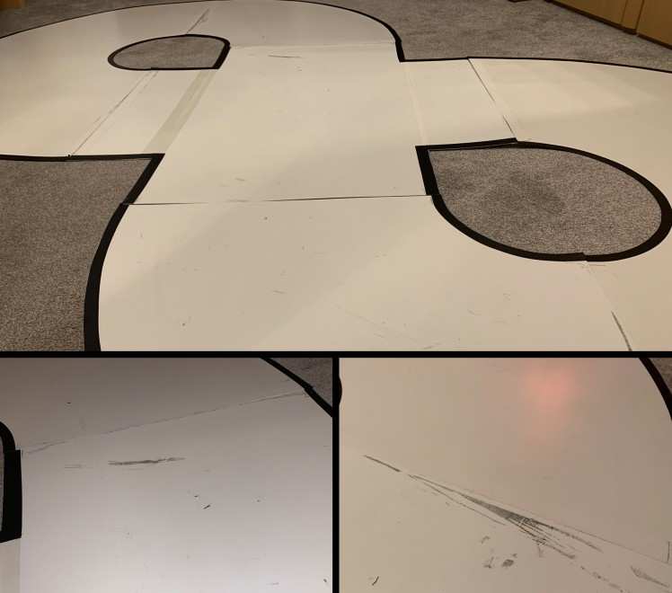
The Test Track
Initially for testing our car we built our test tracks out of paper and black tape markings but those turned out not be durable enough for when the dogs want to go for a spin.
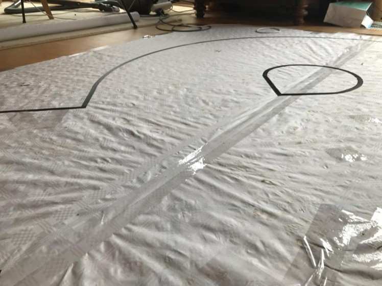
As the test track kit was too expensive for us to obtain, we built our own out of old polystyrol sheets and black tape markings. It has already taken quite a bit beating during our numerous test drives.
Problems Solutions and Lessons learned
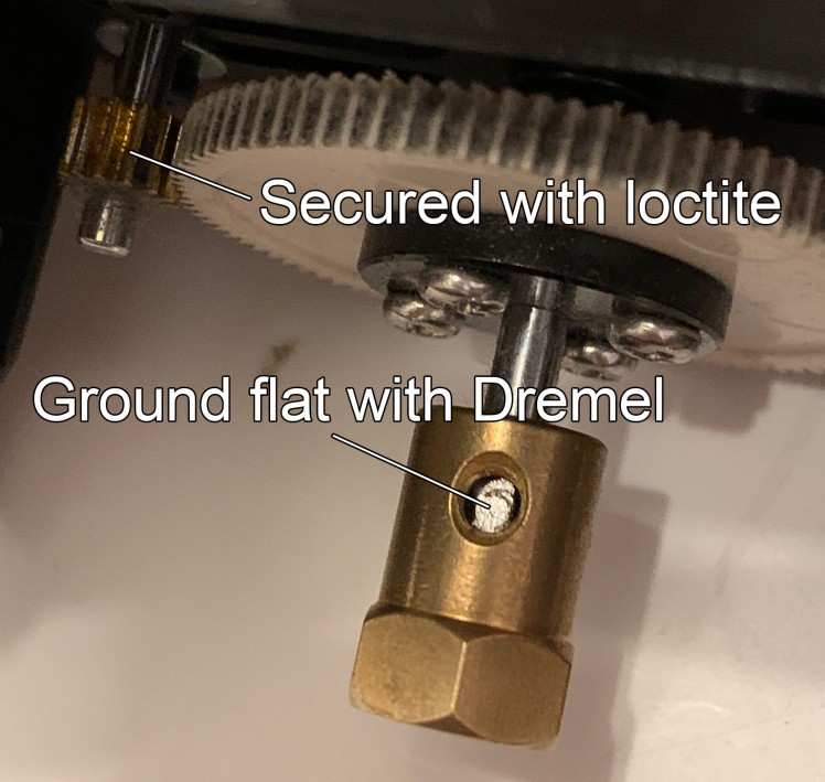
Axle slippage
During our first test runs with the new df robot car kit we noticed that in some situations the spur gear would slip on the shaft of the motor. We solved this slippage by securing it with some red lock tite which is supposed to be the strongest on. While this provided the desired effect, we discovered that now the pinion gear started slipping on its axle, which is the same one that the wheel mount is sitting on, which took the chance and began slipping too. Ultimately the decision was to carve a groove into the axles with a rotary tool, like the one on stepper motors and securing the screws that hold down the spur gear and the wheel mount into those grooves.
Other Problems in no particular order:
- K66F board randomly bricks itself when connected to Windows 10. If your K66F board suddenly shows up as “maintenance” DO NOT disconnect it, that might corrupt the bootloader which makes the board unrecognizable. Just drop a new firmware on it and you’re good. If one were to disconnect said board in that state, rendering the board unusable, one will require an external debug probe such as a JLink to unbrick it (if anyone runs into this problem, feel free to reach out, I spent plenty of time agonizing over this)
- Initially we had problems with track illumination, after four revisions of light arrays we discovered that more LEDs are in fact brighter than fewer LEDs and better track illumination leads to shorter exposure time and more frames per second
- When a sensor draws unusual amounts of power, it is unwise to increase the power limit, as the magic blue smoke contained inside electronics is important for them to function properly and should thus not be exorcized out of them
- One of the KL25Z boards does not provide any serial data whatsoever over the USB port, so we had to use Bluetooth, except for when that does not work either
- When tuning parameters involving the motors, the vehicle should be secured to the work surface as to not fly halfway across the room at eventual unassuming bystanders
- Bluetooth modules are by default set to 9600 baud speed and must be manually set to 115200
- There is a distinct difference between type A and type B flex cables, one will securely connect sensors to your car, the other one will fry your sensor
- One KL25Z somehow randomly died during test by reaching temperatures of up to 200-degree Celsius on the main chip which trips the overtemperature protection. But otherwise remaining full functionality like uploading firmware and software. Without any changes to the hardware, this problem was solved with a new KL25Z board
- Means to stop the vehicle when it goes off track should be implemented early and even sturdy masts will crack eventually
- Uhu Patafix is not a secure solution for mounting magnets to the wheels for use with hall effect sensors for RPM monitoring
- Flimsy stock connections between the components and the battery should be replaced with proper connectors
- As we found that adjusting settings and selecting driving modes solely with the use of buttons and dip switches is inconvenient, we implemented a menu system and a rotary encoder for navigation
- Fast moving objects can be harmful to extremities...especially fingers
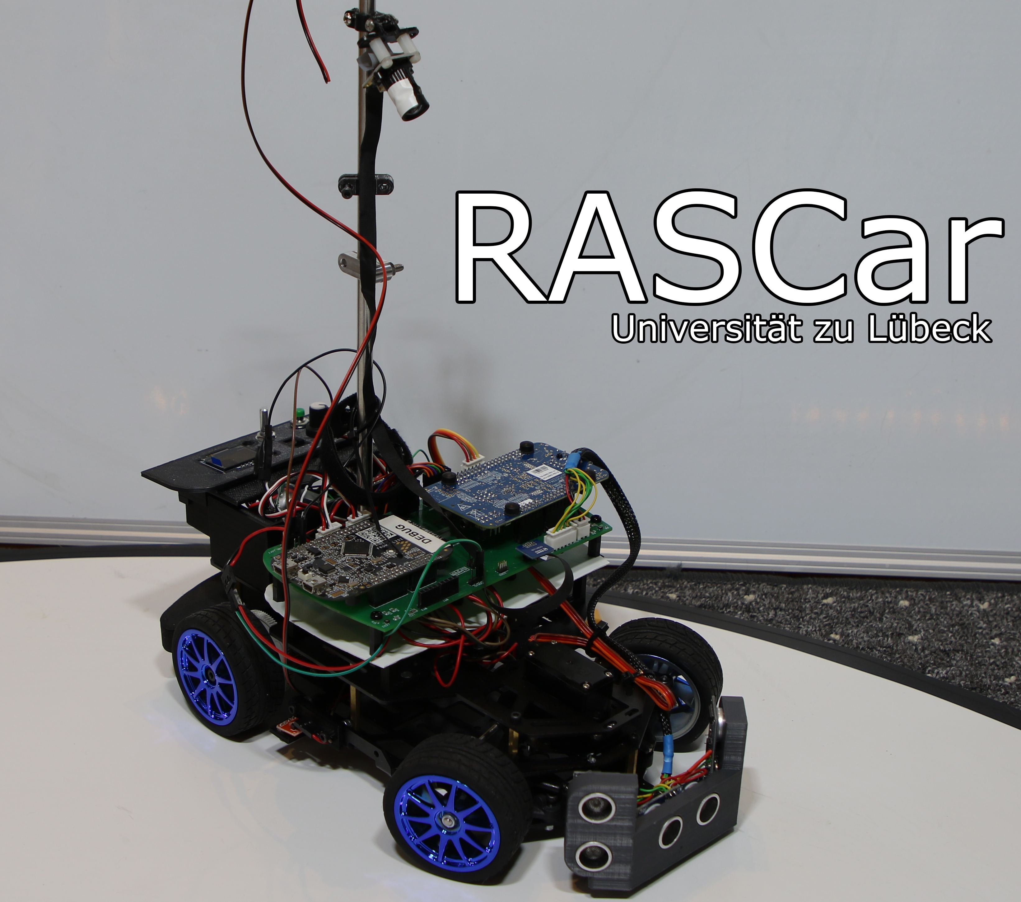
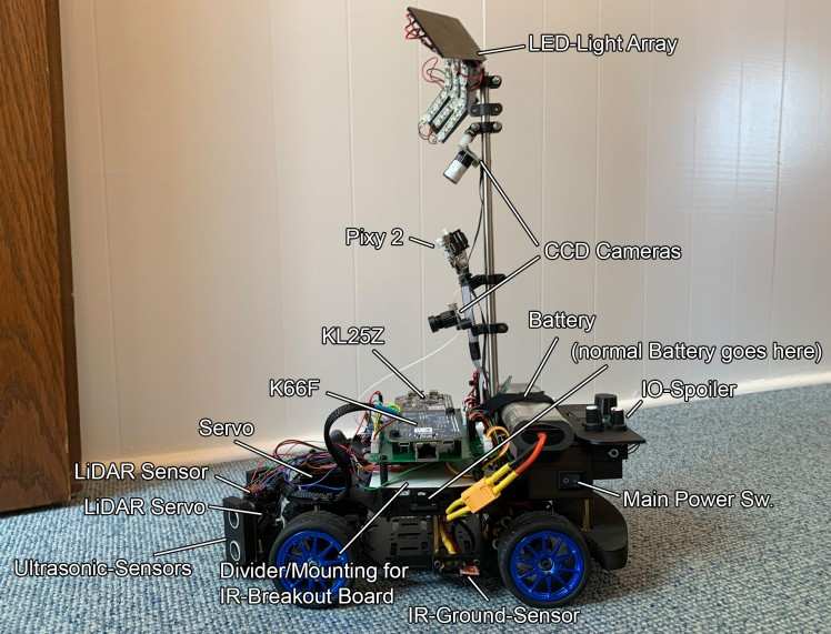
The Finished design

But does it drive?
Where we left off in 2019 and beginning of the progress for 2020:
Figure Eight with wireless Bluetooth telemetry:
Further Progress and all the driving Modes:
Schematics, diagrams and documents
CAD, enclosures and custom parts
Credits
Related products


Leave your feedback...