
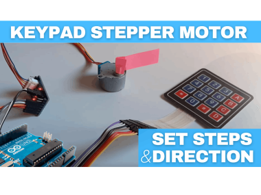
Stepper Motor 28byj-48 Set Steps & Direction Using A Keypad

Made by Ron / 3D Printing / Astronomy / Robotics / Sensors
About the project
In this tutorial we will learn how to control a stepper motor, by setting steps and direction using a Keypad and Arduino.
Project info
Difficulty: Moderate
Platforms: Arduino, Seeed Studio, Visuino
Estimated time: 1 hour
License: GNU General Public License, version 3 or later (GPL3+)
Items used in this project
Hardware components

Story
1 / 5
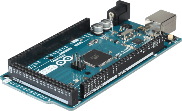

- Arduino MEGA
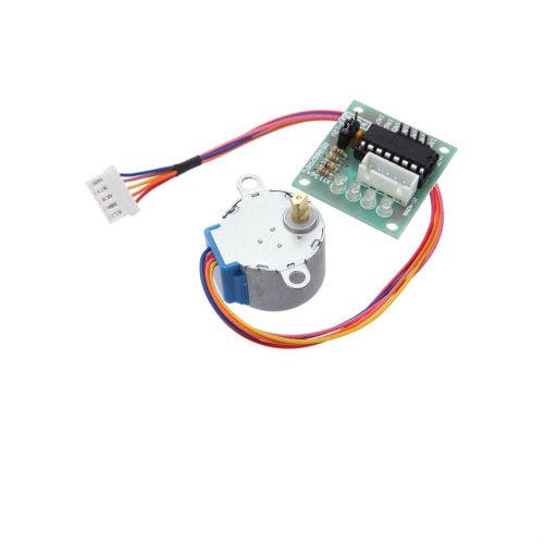
- Stepper motor 28byj-48 & stepper motor driver board
- Keypad
- Jumper wires
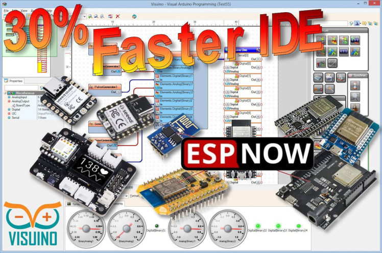
- Visuino program: Download Visuino

Thank you PCBWay for supporting this tutorial and helping users learn more about electronics.
What I like about the PCBWay is that you can get 10 boards for approximately $5 which is really cost effective for professional made boards, not to mention how much time you save!
Go check them out here. They also offer a lot of other stuff in case you might need it like assembly,3D printing,CNC machining and a lot more.
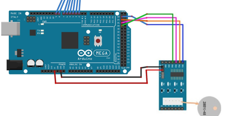
Step 3: The Circuit1 / 2
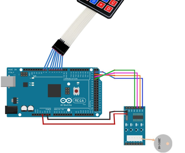
- Connect Keypad pin 1 to Arduino digital pin 2
- Connect Keypad pin 2 to Arduino digital pin 3
- Connect Keypad pin 3 to Arduino digital pin 4
- Connect Keypad pin 4 to Arduino digital pin 5
- Connect Keypad pin 5 to Arduino digital pin 6
- Connect Keypad pin 6 to Arduino digital pin 7
- Connect Keypad pin 7 to Arduino digital pin 8
- Connect Keypad pin 8 to Arduino digital pin 9
- Connect Stepper Motor to Stepper Motor Driver
- Connect Arduino pin [5V] to Driver Board pin [VCC]
- Connect Arduino pin [GND] to Driver Board pin [GND]
- Connect Arduino digital pin [8] to Driver Board pin [IN1]
- Connect Arduino digital pin [9] to Driver Board pin [IN2]
- Connect Arduino digital pin [10] to Driver Board pin [IN3]
- Connect Arduino digital pin [11] to Driver Board pin [IN4]
1 / 2
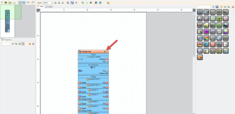
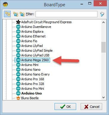
Start Visuino as shown in the first picture Click on the "Tools" button on the Arduino component (Picture 1) in Visuino When the dialog appears, select "Arduino Mega 2560" as shown on Picture 2
Step 5: In Visuino Add Components1 / 12
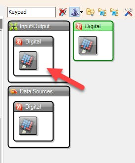
- Add "Keypad" component
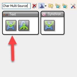
- Add "Char Multi Source" component
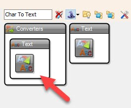
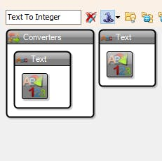
- Add "Char To Text" component
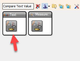
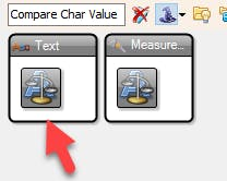
- Add 2X "Compare Char Value" component
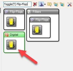
- Add "Toggle(T) Flip-Flop" component
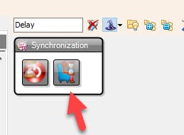
- Add "Delay" component
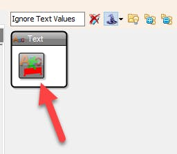
- Add "Ignore Text Values" component
- Add "Text To Integer" component
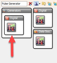
- Add "Pulse Generator" component
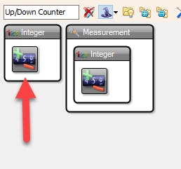
- Add "Up/Down Counter" component
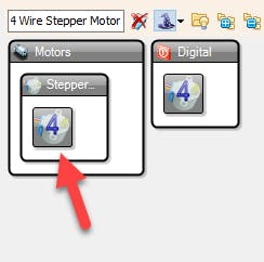
- Add "4 Wire Stepper Motor" component
1 / 16
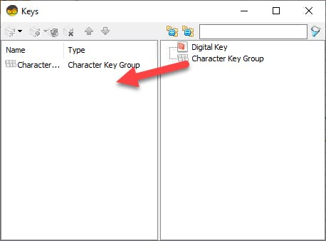
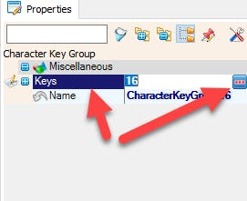
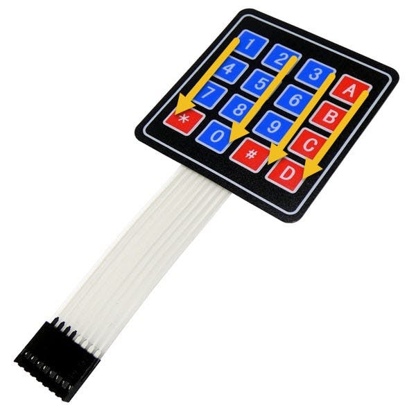
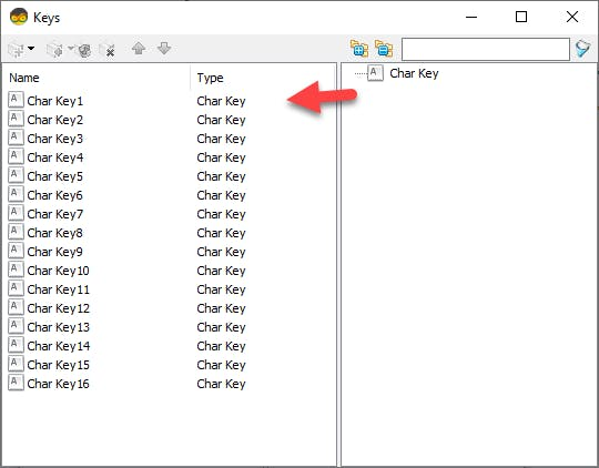
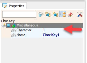

- Double click on the "Keypad1" and in the "Keys" window drag "Character Key Group" to the left side, in the properties window select "Keys" and click on the 3 dot button, now in a "Keys" window Drag 16X "Char Key" to the Left side, and for each key set "Character" in the properties window set "Character" for each in the order like you see on picture 6, for
- "Char Key1" the "Character" will be 1
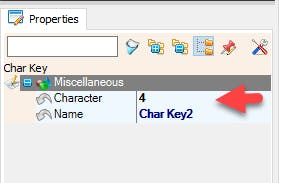
- for "Char Key2" the "Character" will be 4
- for "Char Key3" the "Character" will be 7
- for "Char Key4" the "Character" will be *
- for "Char Key5" the "Character" will be 2
- and so on until the end
- Close All the Windows
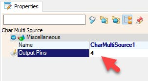
- Select "CharMultiSource1" and in the properties window set "Output Pins" to 4
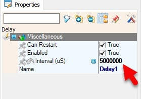
- Select "Delay1" and in the properties window set "Interval (uS)" to 5000000
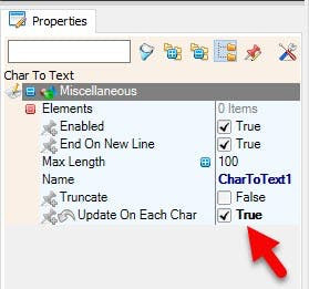
- Select "CharToText1" and in the properties window set "Update On Each Char" to True
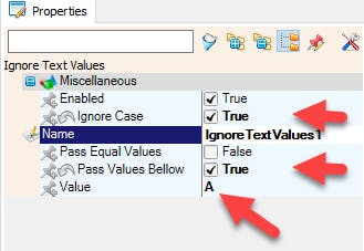
- Select "IgnoreTextValues1" and in the properties window set "Ignore Case" to True, "Pass Values Bellow" to True and "Value" to A
- Select "CompareValue1" and in the properties window set "Value" to A
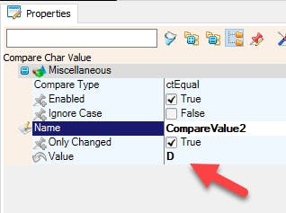
- Select "CompareValue2" and in the properties window set "Value" to D
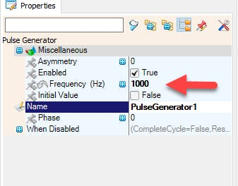
- Select "PulseGenerator1" and in the properties window set "Frequency" to 1000 <<This will be the speed for the stepper motor and you can adjust it if you want
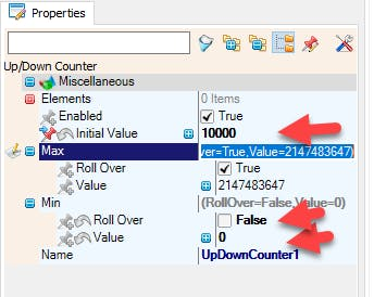
- Here we are going to handle the Steps: Select "UpDownCounter1" and in the properties window set "Initial Value" to 1000, "Min">"Roll Over" to False, "Min" > "Value" to 0
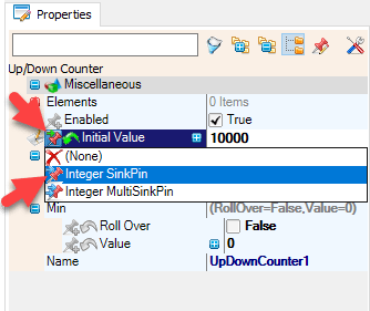
- Select "UpDownCounter1" and in the properties window select "Initial Value" and click on the Pin Icon and select "Integer SinkPin"
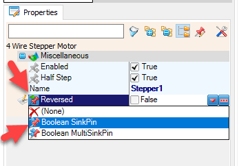
- Select "Stepper1" and in the properties window select "Reversed" and click on the Pin Icon and select "Boolean SinkPin"
1 / 3
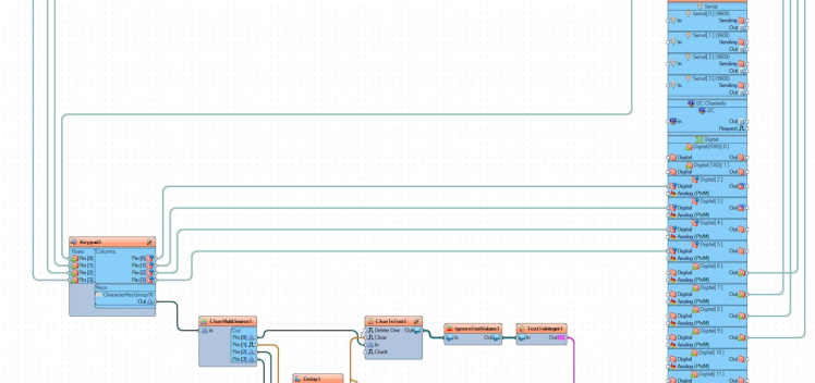
- Connect Arduino Digital Pin[6] to "Keypad1" > Rows Pin [0]
- Connect Arduino Digital Pin[7] to "Keypad1" > Rows Pin [1]
- Connect Arduino Digital Pin[8] to "Keypad1" > Rows Pin [2]
- Connect Arduino Digital Pin[9] to "Keypad1" > Rows Pin [3]
- Connect "Keypad1" > Columns Pin [0] to Arduino Digital Pin[2]
- Connect "Keypad1" > Columns Pin [1] to Arduino Digital Pin[3]
- Connect "Keypad1" > Columns Pin [2] to Arduino Digital Pin[4]
- Connect "Keypad1" > Columns Pin [3] to Arduino Digital Pin[5]
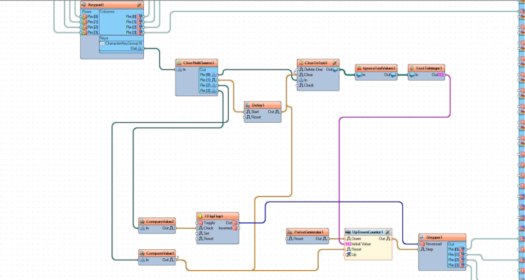
- Connect "Keypad1" > "CharacterKeyGroup16" pin [Out] to "CharMultiSource1" pin[In]
- Connect "CharMultiSource1" pin [0] to "CharToText1" pin [In]
- Connect "CharMultiSource1" pin [1] to "Delay1" pin [Start]
- Connect "Delay1" pin [Out] to "CharToText1" pin [Clear]
- Connect "CharToText1" pin [Out] to "IgnoreTextValues1" pin [In]
- Connect "IgnoreTextValues1" pin [Out] to "TextToInteger1" pin [In]
- Connect "TextToInteger1" pin [Out] to "UpDownCounter1" pin [Initial Value]
- Connect "CharMultiSource1" pin [2] to "CompareValue1" pin [Start]
- Connect "CharMultiSource1" pin [3] to "CompareValue2" pin [Start]
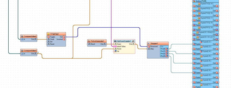
- Connect "CompareValue2" pin [Out] to "TFlipFlop1" pin [Clock]
- Connect "TFlipFlop1" pin [Out] to "Stepper1" pin [Reversed]
- Connect "CompareValue1" pin [Out] to "CharToText1" pin [Clear]
- Connect "CompareValue1" pin [Out] to "UpDownCounter1" pin [Reset]
- Connect "PulseGenerator1" pin [Out] to "UpDownCounter1" pin [Down]
- Connect "UpDownCounter1" pin [Out] to "Stepper1" pin [Step]
- Connect "Stepper1" pin [0] to Arduino digital pin [22]
- Connect "Stepper1" pin [1] to Arduino digital pin [24]
- Connect "Stepper1" pin [2] to Arduino digital pin [26]
- Connect "Stepper1" pin [3] to Arduino digital pin [28]
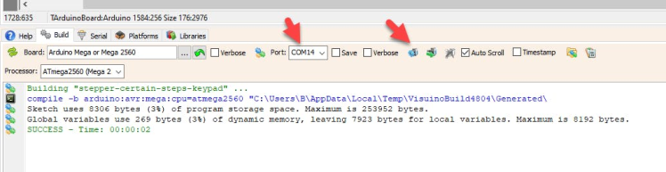
In Visuino, at the bottom click on the "Build" Tab, make sure the correct port is selected, then click on the "Compile/Build and Upload" button.
Step 9: PlayIf you power the Arduino module, and enter the number of steps on the keypad and press the button "A" a stepper motor will start to rotate. If you press a button "D" on the keypad then the stepper motor will change the rotating direction.
Congratulations! You have completed your project with Visuino. Also attached is the Visuino project, that I created for this Instructable, you can download it here and open it in Visuino: https://www.visuino.eu
Schematics, diagrams and documents
Code
Credits
Related products


Leave your feedback...