
Smart Seedling Grow Tray

Made by mahmood_ul_hassan / 3D Printing / Garden / Plants / Sensors / IoT
About the project
An easy to build Seedling Grow System with some brain and remotely management features. It is designed to enable everyone especially children to grow seeds at home without getting worried about over or under watering them. Or are the temperature and humidity friendly for the chosen seeds or not?
Items used in this project
Hardware components


View all
Software apps and online services
Story
Introduction:
Now a day mostly mass produced vegetables and fruits are GMOs, contaminated with dangerous chemical pesticides and traces of chemical fertilizers. And mostly products labeled as organic, are not 100% organic. So the best and most cost effective option to obtain organic vegetables is to produce them at your home.
So now question arises how can you grow vegetables at home without spending too much? Another problem is you can't have a same environmental conditions around the year and building an environment control growing area is very expensive and it will also required a large space. So this project is based on these problems/issue that anyone face and how can you solve it without building a something so big and expensive like mars space station.
CBC documentary about organic foods https://www.youtube.com/watch?v=FFRKK54Tj-c and Farmer markets which are consider as original source of organic produce https://www.youtube.com/watch?v=YYwB63YslbA.
Idea and Working principle:
Build a DIY smart, inexpensive and energy efficient organic garden with environment control feature so you can grow any thing 365 days a year without worrying about the suitable growing conditions. This smart garden will either autonomously control the environmental parameters according to a preset values or it can be remotely controlled and monitored through a cloud interface but with controlled power consumption.
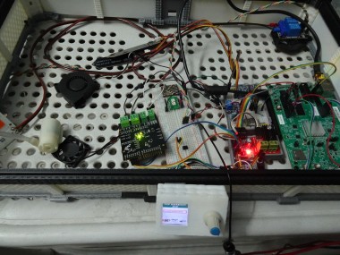
Hardware Used:
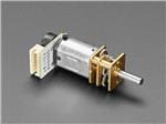
In order to achieve our main goal we need few different types of sensors and control devices. All the main electronics and the hardware used for this project is shown in the video below.
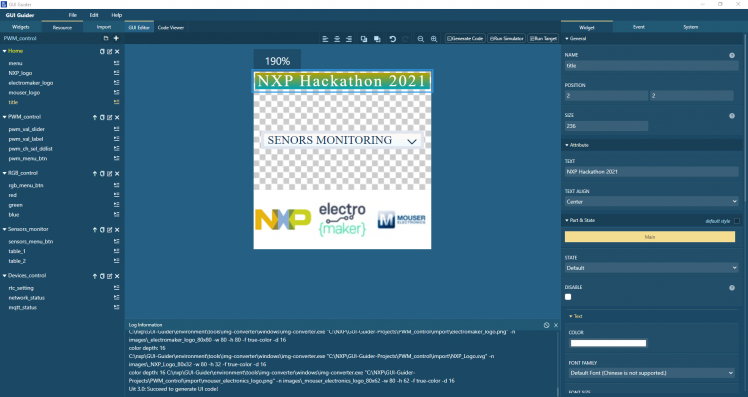
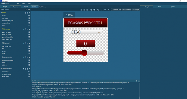
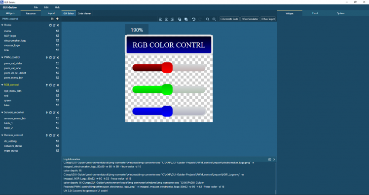
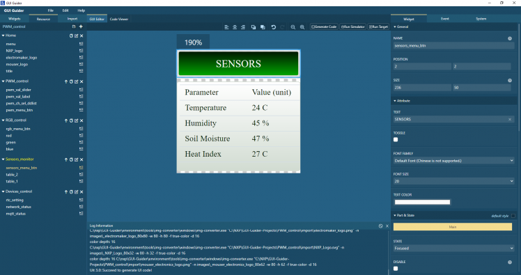
GUI Design:
For better user experience an interactive and easy to use graphical interface is key for the success of any project. To achieve this simple easy to use GUI with all the necessary controls in designed using NXP GUI Guider software which is used to generate graphics files to use with lvgl graphics library. Apart from using GUI Guider lots of custom code is added for handling all the events and adding rotary encoder as control input to interact with on screen information instead of touch display.
Demo of GUI:
After few additional GUI element additions and all the event handlers coding the Final graphical user interface for this project looks likes as shown below in video.
Hardware Demo:
All the demos with GUI control and monitoring are given below:
Sensors Demo:
Device Control Demo:
RGB Demo:
All the codes with sensors custom C libraries, GUI design files in C, MQTT interface setting, setting for using external on board SD RAM, 3D printed parts files are given in the repository attached below.
Code Details:
Project code is pretty big so here all the main points and important things required for successfully building this project are explained below;
External modules:
Initially it will look like MIMXRT1020 Evaluation Kit have lots of external GPIO and you will be able to control lots of external hardware. For some it extend its true. But if someone want to use this device as an IoT device and use its on board Ethernet interface for network communications then you are just out of luck. Because after using the onboard ethernet connection you will be left with 5 GPIOs of J18 (Arduino Analog Pins), 3 GPIOs from J19 (including one GPIO used for SD_card Voltage select) and 3 GPIOs from J17 (excluding 2 GPIO used UART communication with Debug interface).
In order to make things happen lots of external modules are used. All the details of external modules connection with MIMXRT1020 Evaluation Kit with interface name, is given below.
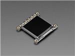
ST7789 IPS LCD ==> SPI3 (only SCK, SDO are used to save GPIO for COB LED relay control and DHT22)
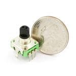
Rotary Encoder ==> ENC1 (at Arduino header j17 pin 1 and 2 (Arduino D0 and D1)
Rotary Encoder Button ==> At Arduino header j17 pin 5 (Arduino D4)
All the I2C devices ==> At Arduino header j19 pin 9 and 10 (Arduino D14/SDA and D15/SCL)
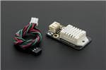
DHT22 ==> At Arduino analog header J18 pin 4 (Arduino A3)/ Unused SPI3 PSC0
COB Led Relay ==> At Arduino analog header J18 pin 5 (Arduino A4)/ Unused SPI3 SDI
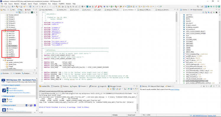
All the sensors and I2C devices C code are placed in ext_modules source folder with ext_modules wrapper functions for providing easy to use functions.
LCD:
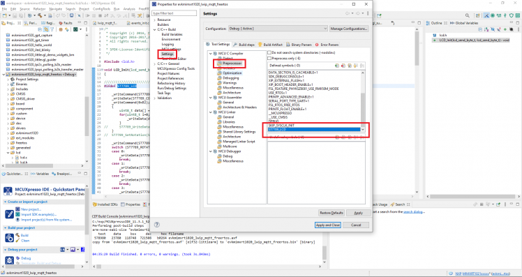
SDK ILI9341 Graphical LCD code files and functions are renamed to lcd and added the support for ST7789 graphical display as well in its initialization function. Now user can easily switch LCD type by adding the "defined symbols" in project settings.
ST7789_LCD ==> for ST7789 LCD
ILI9341_LCD ==> for ILI9341 LCD
As we are using external SD RAM as main RAM so its important that we defined our SPI data variable that will be transferred over DMA, in non cacheable region of our external RAM as defined in system memory configurations as shown below;
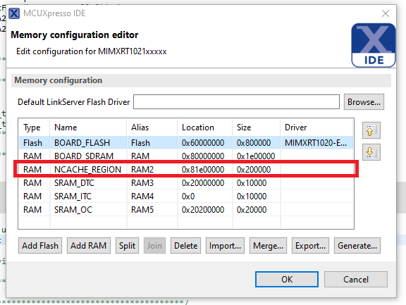
One can manually initial LCD buffer in above non cacheable set region and then do the memory aligned or it can be done by using the SDK macro "AT_NONCACHEABLE_SECTION_ALIGN_INIT"
As we have defined a plenty of none cacheable region (2MB) in external SDRAM so we are using dual framebuffer configuration for lvgl library for even more faster display updates.
- AT_NONCACHEABLE_SECTION_ALIGN_INIT(static uint8_t s_frameBuffer[2][LCD_VIRTUAL_BUF_SIZE * LCD_FB_BYTE_PER_PIXEL], 4);
- AT_NONCACHEABLE_SECTION_ALIGN_INIT(uint8_t tft_spi_data[4], 4);
Variable " tft_spi_data" is used to send all the commands through DMA
Code
Credits
mahmood_ul_hassan
Electronics Engineer with specialization in Robotics Engineering, seven years of experience in electronics research and development. I worked mostly on designing custom labview based automatic test and measurement equipment. Hobbyist, ARM enthusiast, DIY maker

Leave your feedback...