

Smart Hives: Beehaviour Monitoring

Made by MariaG / 3D Printing / Communication / Environmental Sensing / Sensors / IoT
About the project
The Beehaviour Monitoring project consists of beehives equipped with sensors (Broodminder Weight Scale and Nordic Thingy:52) for monitoring the state of the hive. The data is processed on site on an nRF5340-DK, and then sent to a cloud service (nRF Cloud) for storage and visualization.
Project info
Difficulty: Moderate
Platforms: Nordic Semiconductor
Estimated time: 3 months
License: MIT license (MIT)
Items used in this project
Hardware components


View all
Story
DISCLAIMER: This project has also been posted in its entirety on Nordic Semiconductor's forum, DevZone. This is where the source code can be downloaded from as well.
In the last few years, the field of IoT and especially smart home applications has seen a near exponential growth in both customizable protocols and out-of-the-box applications which everyone and their mother have in their homes. These applications are often well suited for their environments, e.g. monitoring and controlling a home, but may be less customizable than what some desire.
The thought that hit us – a group of students studying Electronics Systems Design and Innovation and Cybernetics and Robotics at NTNU – was the highly customizable possibilities we have with Nordic’s products. Through a wide range of development kits and prototype platforms for Bluetooth LE communications there are limitless possibilities of services for monitoring, sampling, and visualizing data together with nRF Cloud. These products can be used to create your own smart home systems, such as seen in the Zigbee Smart Home Demo, or applied to any general system one desires.
This generality is what led to our summer project, which was to use Nordic products to create a scalable system which monitors and extracts useful data from a beehive and to display how one may use Nordic products in a more general environment one may want to “smartify”.
In addition to displaying how the prototype developed in the summer project may translate to any kind of environment, it also aimed to make quality-of-life improvements for beekeepers in both urban and rural areas. An extensive portion of beekeeping is time invested in monitoring hive health. Also, if the hive is located far away from the beekeeper's day-to-day habitat, there is also a time- and emission cost in transport from home to hive. The time investment from monitoring may be greatly reduced by applying a low power solution for monitoring, modeling, predicting and visualizing hive health through Bluetooth LE and LTE communication between a hive located anywhere and the beekeeper!
Model overview
The first challenge of the project was to draft a system which included sensor modules, a unit for data processing and a unit for cloud communication. The system should also be easy to scale to multiple beehives, and the data uploaded to cloud should also be as useful as possible to minimize sending redundant data and reduce power consumption.
The result of this draft divided the prototype into two sub-systems: one consisting of an easy-to-scale basis system, and one consisting of an expansion system. The basis system contains the most needed sensors, such as the weight scale, the internal sensing unit monitoring temperature and humidity, the data processing unit, and the cloud unit. The expansion system consists of other sensors such as the Bee Counter and the woodpecker alarm which require its own hardware and can be added to the basis system where one considers it necessary.
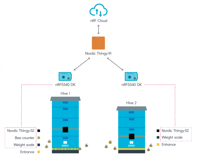
Picture text: Draft of prototype.
The modules and units in the two systems are described in more detail in the following sections!
Sensors
The Beehavior Monitoring prototype uses three sensor units. The internal sensors are all part of the Thingy:52, and the external sensors are the BroodMinder-W weight scale and the Bee Counter. A fourth sensor unit is the woodpecker alarm, an external sensor, but this is not yet connected to the rest of the system. The following sensors are the only ones that are supported by the prototype this far, but further support for other Bluetooth LE sensors can be added.
Internal sensors - Thingy:52
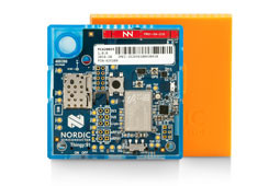
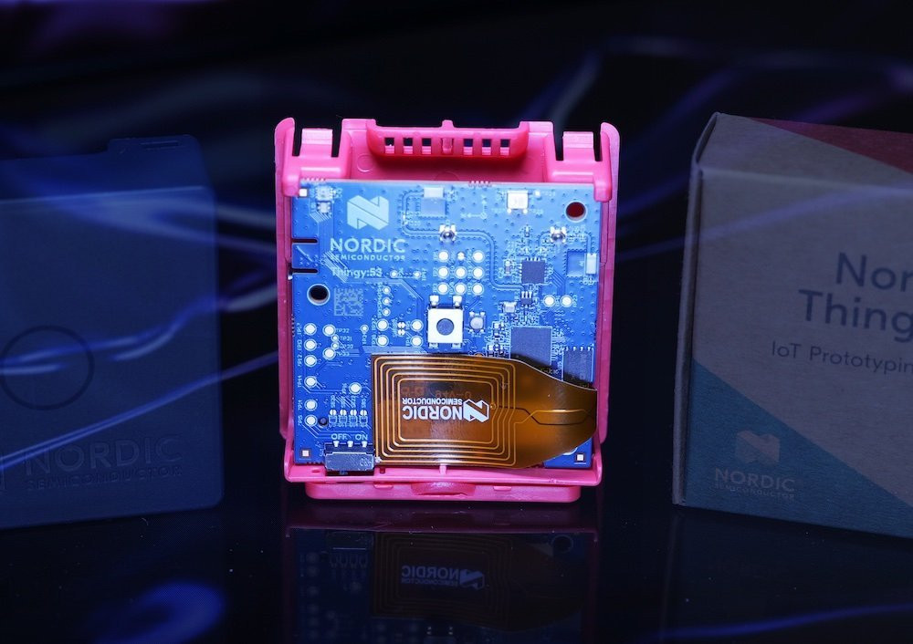
Nordic’s Thingy:52 prototyping platform is placed inside the hive to measure temperature, humidity, and air pressure. Our project is based on standard Thingy:52 firmware, which means the unit works out of the box. If desired, it is also possible to subscribe to additional Thingy-services by adding the UUID in a similar fashion as done in the Beehaviour Monitoring prototype. For instance, the orientation service can be used to trigger an alarm if the hive has been toppled or physically moved.
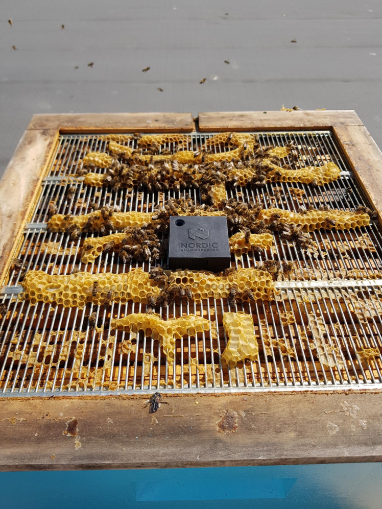
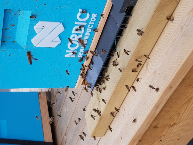
Picture text: The placement of the internal Thingy:52-unit placed on top of the queen excluder.
External sensors - Bee Counter
The Bee Counter is based on Easy Bee Counter, an open source project. It was expanded to include Nordic’s peripheral UART example to send the data to the nRF5340-unit. The concept of a Bee Counter might seem simple at first glance, but the data gathered could be used in a plethora of ways! Rate of expansion or decline of bee flights might indicate hive health, timing shift between peaks of bee traffic might indicate numbers of foragers and distance to pollen/nectar source. Lastly, the rate of expansion or decline of orientation flights might also suggest the current health of the bee queen, as it might correlate with her fertility rate. The data a Bee Counter provides may in other words be proven to be extremely useful and insightful.
The Bee Counter consists of 24 individual gates with 48 optical sensors (two in each gate). By utilizing two sensors in each gate, one could differentiate if a bee is present or not, and if it is going in or out of the hive. Each optical sensor is supplied with the qre1113, an IR LED and an IR sensor. If no bees are present, the light is absorbed on the bottom PCB which is black. However, if a bee is present, the light bounces off the bee and into the sensor, thus triggering it. The LEDs are divided into two sets of 24, which is controlled by an FQP30N06 N-channel MOSFET.
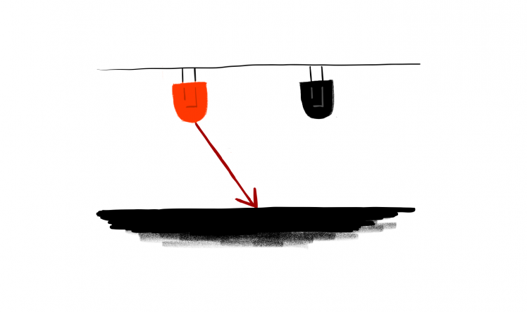
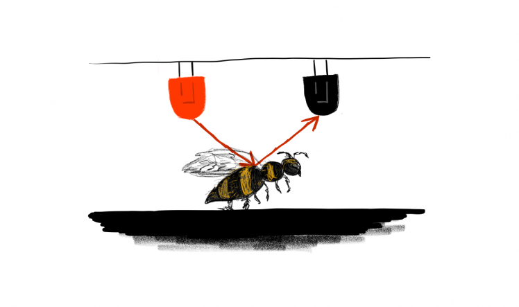
Picture text: Illustration over the basic concept, no bees means the black surface absorbs the wave, a bee present will make the IR wave bounce off and onto the receiver.
There are in total 6 74HC165 input shift registers and each register save data from 4 gates. All shift registers are read simultaneously over the microcontrollers SPI pins. Sensors are pulled as logic LOW when no bee is present and is pulled to logic HIGH (or 3.3V) when there is a bee present.
On average, a bee typically uses about ~150ms to transverse a gate, thus it is relatively safe to assume that a bee will have a travel time of less than ~650ms. To mitigate the issue of bees walking around outside the gate triggering an outside sensor, we need to implement a check for the second sensor to trigger. The exact time for triggering the second sensor is arbitrary but should be relatively low, as the sensors are pretty close together. The following code snippet is this check.
- if(inSensorReading[i] == false)
- {
- lastInFinishedTime[i] = current_time;
- inReadingTimeHigh[i] = current_time - startInReadingTime[i];
- if(outReadingTimeHigh[i] < 650 && inReadingTimeHigh[i] < 650)
- {
- if((current_time - lastOutFinishedTime[i]) < 200){
- outTotal++;
- }else{
- break;
- }
- }else{
- break;
- }
- }
It is safe to assume that this should be less than ~200ms, considering miniscule distance between sensors in each gate.
Code from the original project has been ported to support the Zephyr RTOS and includes the Adafruit itsybitsy nRF52840.
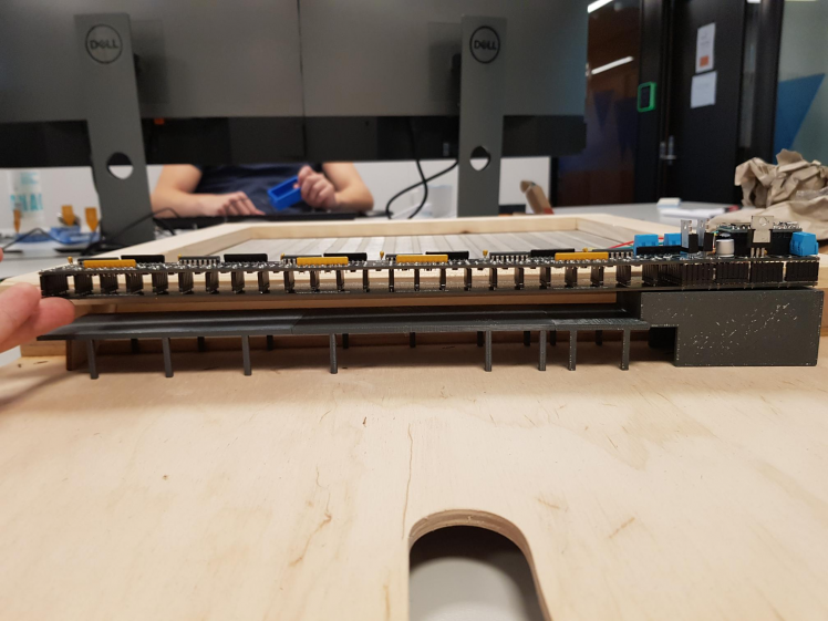
Picture text: The Bee Counter with a 3D-printed cover for protection of the elements. Blender files and compiled .stl files can be found in the attached .zip.
External sensors - Woodpecker alarm
A feature of the nRF5340 DK is that we can use machine learning on a microprocessor. An idea that came to mind was to record audio from the beehive and use this together with machine learning to determine the health of the beehive. After investigating the possibilities for using audio to determine hive health, we concluded that there was not enough time to develop a proper model for this purpose. Instead, we moved on to another audio-based module: the Beehavior Monitoring Woodpecker Detector.
To utilize machine learning on the nRF5340 DK, we are using Edge Impulse, a platform for machine learning on embedded devices. They provide ways to create new machine learning models, train them with data you collect or existing datasets, and deploy a trained model to an embedded device. The classification is then performed by the on-site device, and the results forwarded at suitable intervals.
Using a X-NUCLEO-IKSO2A1 shield featuring a microphone, we made a machine learning algorithm to recognize the sound of a woodpecker near the hive, and send an alert over Bluetooth to a device running the nRF central_uart example. This could also be augmented to send an SMS warning to the beekeeper when the alarm is triggered.
Due to time limitations, we did not have time to perform a field test nor to add this to the rest of the project, but we plan to do that in the future. However, the code attached in the zip can be run separately with the required hardware.
An idea for further developing this part of the expansion subsystem is to modify the code and flash the edge impulse to the internal Thingy:52-unit to avoid having an additional external module.
The woodpecker detector machine learning algorithm was created using Edge Impulse studio, a public version of the woodpecker detector project can be seen here, and the readme attached for this module in the zip explains how to use Edge Impulse and this module to a greater extent.
External sensors - BroodMinder-W scale
BroodMinder’s Bluetooth based scale was used to track the weight of the hive as well as the temperature outside of the hive. The nRF5340 unit scans for the scale by address. BroodMinder sensors address are “06:09:16” plus the name of the sensor, e.g. “06:09:16:57:01:FD” if the sensor name is “57:01:FD”. When the sensor is found, the nRF53 unit reads the scan response packet from the sensor and turns it into weight and temperature according to Appendix B in the BroodMinder user guide (pdf-download).
The hive is then raised and placed on top of the scale in one end of the hive and a two” by four” plank in the other end, as suggested by Appendix A in the user guide, except for adjusting the measurement to accommodate for the location of the center of mass. The result of this is that the hive is approximately two times heavier than what the graph in the later section displays. The fix is simple, add a line of code to multiply the scale weight by 2.09 before sending the weight data to the cloud.
Processing and cloud units
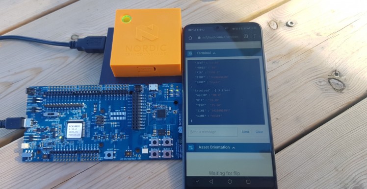
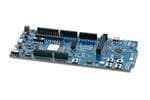
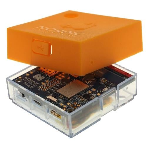
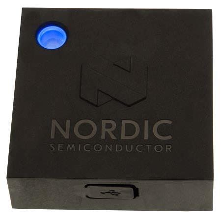
Picture text: The processing- (nRF5340dk) and cloud- (Thingy:91) units displaying a transmitted message on nRF Cloud.
The model is based on one nRF9160 unit, either an nRF9160 development kit or a Thingy:91, acting as a hub. These boards have an nRF9160 chip that supports LTE-M/NB-IoT to communicate with nRF Cloud, and one nRF52840 chip to communicate over Bluetooth. The nRF9160-unit can connect to up to 19 peripherals, which are the nRF5340 development kits, where each peripheral represents one hive. Although the system can scale to 19 hives, we have only had a field test with two hives available for testing.
The nRF9160-unit turns data received from the peripheral units into JSON-formatted message, which is sent to the cloud with a timestamp and the name of the peripheral it received it from, for instance “Hive1”. The nRF9160-unit can also receive messages from the terminal in nRF Cloud, such as “StartScan” to make the unit scan for peripherals.
The nRF5340-units serve two different purposes; Primarily, they perform data preprocessing/edge computing to reduce the amount of data sent from the nRF9160-unit to nRF Cloud. In addition, they act as a central hub which collects data from the internal and external sensors.
The nRF5340-units also features multi role properties where it acts as a central for the sensing units such as the Thingy:52, Bee Counter (Adafruit itsybitsy nRF52840) and the BroodMinder scale. At the same time, it is connected to the nRF9160-unit as a peripheral. This way it can receive data from multiple peripheral units, process it and send it to the central unit, which relays it to nRF Cloud. The data is stored and can be accessed through nRF Cloud’s REST API.
The nRF5340-units can either read the advertising data from peripheral units or connect to the units and subscribe to notifications. To read the advertising data the unit must scan for the peripheral with a chosen interval. By subscribing to notifications, the nRF5340-unit needs a received function for each service subscribed too.
Another purpose of the nRF5340-units is to perform data preprocessing/edge computing to reduce the amount of data sent from the nRF9160-unit to nRF Cloud. This is further elaborated on in a later section about edge computing.
Both the connection and the sending of data between the nRF5340 and the nRF9160 are based on the Nordic UART Service library.
Using nRF Cloud and REST API
The last part of the project, except cleanup, robustifying, and the vast further work list, consisted of representation of sensor data and developing a platform which could illustrate the gathered data from the hardware modules. This part of the blog explains what we used this summer, how we used it and some of the results we achieved.
nRF Cloud
nRF Cloud is Nordic Semiconductor’s IoT cloud service, and is documented on docs.nrfcloud.com. Our nRF9160 device(s) was added to one of our accounts and messages were sent from the device to the cloud. From nRF Cloud we could also send messages from a terminal in the web interface to the device. All messages sent either to or from the device need to be in JSON format.
A small limitation for historical messages is that nRF Cloud saves them for a maximum of 30 days. For situations where data older than 30 days is necessary, a separate storage solution is needed.
REST API
The messages the nRF9160-unit sends to nRF Cloud were accessed by using nRF Cloud’s REST API. More specifically, the endpoint used was ListMessages, which is documented here. When retrieving historical data, the endpoint was accessed multiple times until all messages in the wanted time interval had been retrieved.
The implementation of the REST API functions is mainly found in the GitHub repository NordicPlayground/nrf91-pizza. In addition to the functions implemented in the file js/cloud-api.js, an additional function for retrieving more messages was implemented. All the functions are a member of the class NRFCloudAPI which is initialized with the API key of an nRF Cloud account. It is saved as an access token of the class and used to authenticate the account when endpoints are being accessed.
The following code snippet shows the implementation of the function which retrieves older messages.
- getOlderMessages(deviceId, msecs_end, msecs_back) {
- const end = new Date(msecs_end);
- const start = new Date(msecs_end - msecs_back);
- const devIdsParam = deviceId ? `&deviceIdentifiers=${deviceId}` : '';
- return this.get(`/messages?inclusiveStart=${start.toISOString()}
- &exclusiveEnd=${end.toISOString()}${devIdsParam}&pageLimit=100`);
- }
When getOlderMessages() is called, it is paired with a loop, which ensures that all messages in a valid time interval is fetched. This method has a limitation for the free nRF Cloud account, which is a maximum of 100 calls to ListMessages. This limitation can be worked around by utilizing pageNextToken, which is part of the response schema from ListMessages.
After fetching the messages, wanted data with associated time stamps are acquired, and can be represented in a suitable way on your website. In this project we have used Google Charts to plot data.

Picture text: An example for representing recent sensor data in graphs and info boxes.
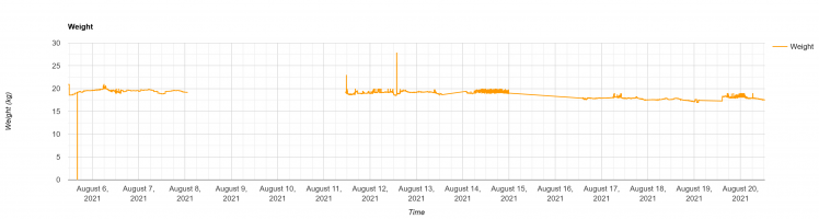
Picture text: An example for representing historical sensor data in a graph. Empty area represents a time interval with invalid data.
Future Improvements
As with any prototype there are always improvements to be made regarding robustness of the system and optimization of power consumption. As of now the cloud unit consumes a lot of energy because up to three messages per minute per hive are sent to nRF Cloud. The Thingy:91 with a fully charged battery connected to two beehives and sending three messages per minute, operated for 4 days and 8 hours before running out of power.
One straightforward way to cut down on power consumption is to send fewer messages and bundle the messages together so the modem can sleep as much as possible. By increasing the interval between sending messages to the cloud from one minute to twenty minutes, there should be a drastic increase in operation time for the prototype.
A revision of the Bee Counter hardware would be optimal, as the double footprint has caused voltage to go to the through hole for the feather microcontroller. A suggestion would be to use a micro:bit v2 instead, and have it clip on the bee counter, thus negating the previous issue. However, this would require a complete overhaul of the PCB.
Development of new expansion system modules
Pushing the processing unit more by using the gathered sensor data to implement a nectar to honey evaporation prediction model. By using sensor data to create a model based on the equations written in a paper published in 2019, we believe we can create a (simple) state estimation model which can predict the rate of water evaporation required to ripen honey and in turn estimate the amount of honey inside a hive at any given time.
Another addition which may push the processing unit further is the addition of machine learning on audio recorded from inside the hive. A paper “On the Importance of the Sound Emitted by Honey Bee Hives" suggests that some of the most promising systems for monitoring the health of honeybees and beehives are audio based. This gave rise to an idea of trying to train a machine to recognize the mood of the hive through audio, which may give information about hive health and in turn may prevent Colony Collapse Disorder (CCD).
Again, another addition of machine learning that could be interesting to investigate is the addition of machine learning on images of the bees that enter the hive. Based on the color and amount of pollen attached to the bees’ legs, one can estimate the type and amount of pollen in the air in that specific area. This can develop an even better understanding of how to estimate a pollen count, which might be more accurate than the pollen counts existing today.
But some of these expansion system modules may be too complex for an autumn with part time work for the student group and may be more suited for another year’s summer project, or someone's bachelor’s-, or even a master’s thesis!
Thank you to Paul and Alexander at Heier Du Rietz who provided necessary equipment and information as well as performing the beekeeping.
Credits
Related products


Leave your feedback...