
Simple Rgb Desktoclock Using Attiny85

About the project
RGB Desktop clock using ATtiny85 and neopixel
Items used in this project
Hardware components

Software apps and online services
Story
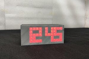
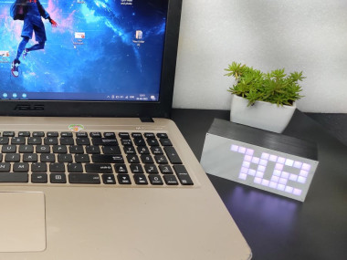
I wanted to make a customised clock for my desk. With the help of neopixel LEDs, I decided to build my own digital clock that is good enough to display the time while I am working. in this clock, we can change the time time, digit colour and brightness. so let's get started with the making.
COMPONENTS NEEDED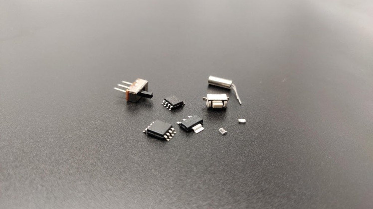
ATtiny 85*1
WS2812B LEDs *54
RTC DS1307*1
AMS1117-5.0*1
Switch*1
10k*1
Diode_4148*1
Slide Switch*1
32.768kHz crystal oscillator *1
TP4056 li-ion battery charging module
18650 li-ion battery
First, I selected neopixels for the clock because we need only one pin to control all LEDs and we can simply display different colours. To display a digit we need at least 5 rows and 3 columns of LED. So that way I designed the one-digit segment like this. that is we need 13 LEDs for one digit. And we have 4 digits which is a total of 52 neopixels. Also, I added two more LEDs for the second indication. I added ds1307 rtc ic to the circuit for saving time.
CIRCUIT DIAGRAM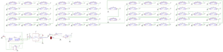
I designed the circuit on easyeda. Here I arranged the RGB LEDs like a digit pattern and each digit consists of 13 LEDs. also, I added 2 LEDs for the second indication. the SDA and SCL pins of rtc ic are connected to pins 5 and 7 of the attiny.
Download the circuit diagram from here
PCB DESIGNING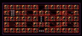
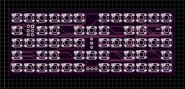

Soldering this 54 Led and other components with the hand is not practical so I converted the circuit into a PCB. First, I arranged the LEDs on the top side of the PCB. Then in the bottom layer, I arranged all other components and finished the PCB design. After finishing the design our PCB looks like this. So next I generated and downloaded the Gerber files for PCB fabrication.
Download the Gerber files from here
PCB FABRICATION
To fabricate the PCBs I went to JLCPCB.com. jlcpcb offers only 2 dollars for 5 awesome PCBs and their PCB assembly starts from 0 dollars.
Get JLCPCB $54 new user coupon: https://jlcpcb.com/ESC
To order the PCBs just click on order now and upload the Gerber file then you can select the colour thickness quantity etc. In this case, I choose the purple colour. After that, I selected the shipping method and placed the order.
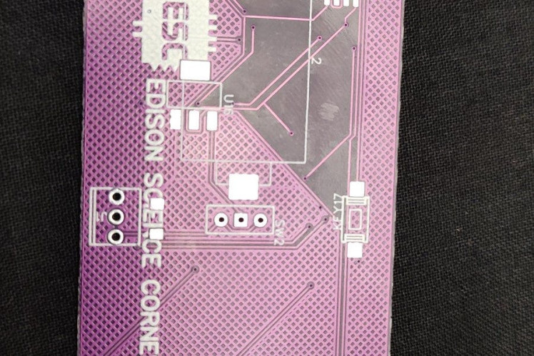
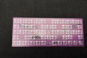
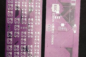

After two weeks I received the PCBs the purple colour PCBs look great and the quality is superb.
SOLDERING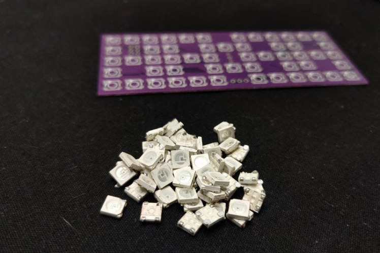
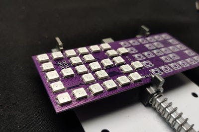
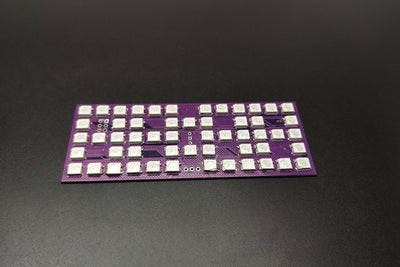
Next, I grabbed the Neopixel LEDs. we have to Solder 54 LEDs to the PCB doing that by hand makes pain so I decided to use the reflow method. So first I dispensed the solder paste with a needle. Then I placed every LEDon the correct pads. After finishing this I placed that in my DIY hotplate and cooked it. After the reflow of the LEDs, our PCB looks like this. Now we have to solder the components on the downside of the PCB. here we cant do the reflow method because one other side is already soldered with LEDs. so I soldered each component by hand.
PROGRAMMING AND TESTING
I connected the spi pins attiny to an Arduino and Programmed the attiny85 and now I connected the battery to the clock and here you can see the result. It is working perfectly but you can see that the LED's light diffused together and gives out mixed light.
Download the Arduino code from here
ENCLOSURE DESIGNING AND 3D PRINTING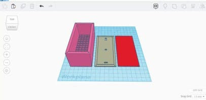
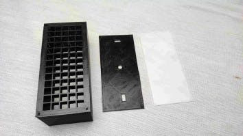
To solve this I designed an enclosure in tinkerkad and 3d printed the design using my ender 3v2. We have three different 3d parts. The base with a led jig, the back cover and the front panel.
Download the 3D files from here
FINAL ASSEMBLY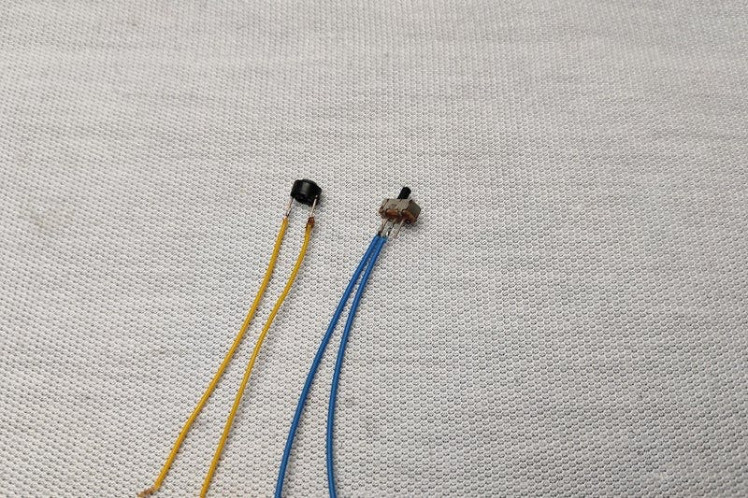
Next, I desoldered the button and switch from the clock PCB and connected flexible wires to it.
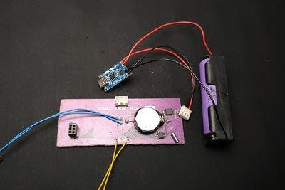
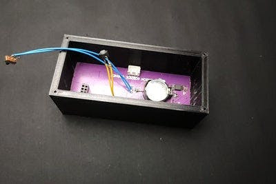
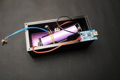
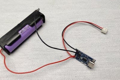
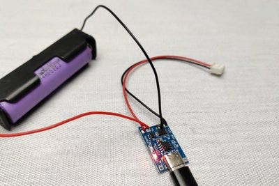
Then I soldered the switch and button to its pads and inserted the neopixel PCB into the jig. Here I added the tp4056 charging module to a lithium-ion battery and connected it to the circuit. on the back cover, I glued the tp4056 charging module, push button and the switch. finally, I closed the cover. For the front panel, and I glued it to the front side and that's it.
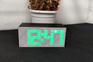
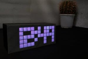
HOW TO SET TIME/COLOUR/BRIGHTNESSNow You can see the work looks nice right. We can change the time, colour and brightness for that just press the button and then press it again to change the colour. After selecting the colour wait for 3 seconds to select the brightness we can set it from 0-10 after that we can set the hour and minute and that is it.
HAPPY MAKINGSo this is how I made the Attiny85-based Neopixel clock. That's all about today. hope you enjoyed and learned something from my tutorial. I will see you next time
Schematics, diagrams and documents
Code
Credits
Related products


Leave your feedback...