
Simple Lcd Battery Level Indicator 20x4 I2c

About the project
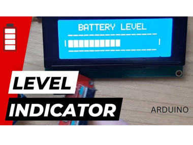
In this Tutorial we are going to make a Battery Level Indicator using LCD I2C 20 X 4 Display.
Project info
Difficulty: Easy
Estimated time: 1 hour
License: GNU General Public License, version 3 or later (GPL3+)
Items used in this project
Hardware components

Story
This approach can be used to display anything that requires a level indication such as batteries, water level, temperature, humidity, etc.
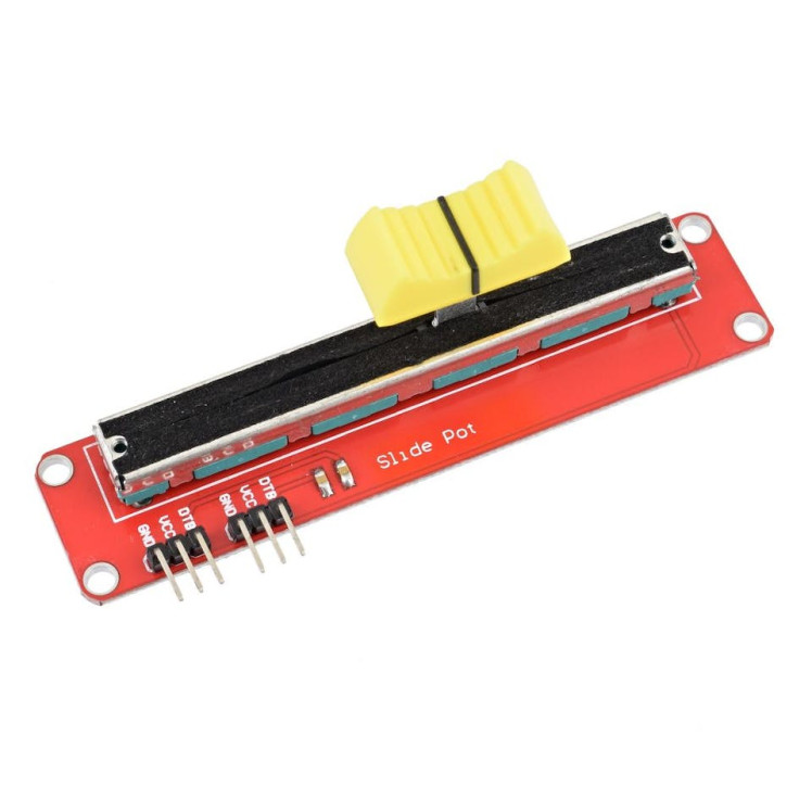
For the demonstration we are going to simulate the signal with a potentiometer connected to Analog pin to get us the input voltage from 0V to 5V.
Watch the video!
Note: In the attached files you will find two files one is for the battery indicator with a surrounding frame and one is without the surrounding frame.
Step 1: What You Will Need1 / 5
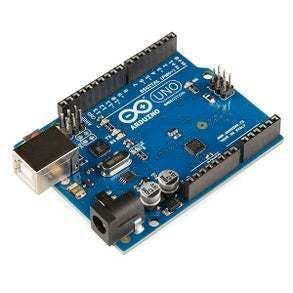
- Arduino UNO (or any other Arduino or ESP)
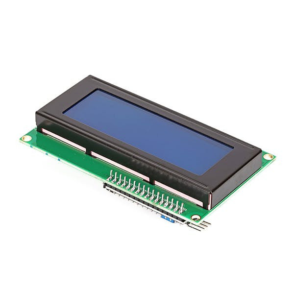
- LCD I2C
- Potentiometer module
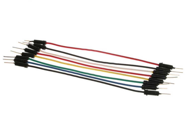
- Jumper wires
- Visuino program: Download Visuino

Thank you PCBWay for supporting this tutorial and helping users learn more about electronics.
What I like about the PCBWay is that you can get 10 boards for approximately $5 which is really cost effective for professional made boards, not to mention how much time you save!
Go check them out here. They also offer a lot of other stuff in case you might need it like assembly, 3D printing, CNC machining and a lot more.
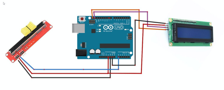
- Connect potentiometer pin [DTA] to arduino analog pin [A0]
- Connect potentiometer pin [VCC] to arduino pin [5V]
- Connect potentiometer pin [GND] to arduino pin [GND]
- Connect LCD pin [SCL] to Arduino pin [SCL]
- Connect LCD Display pin [SDA] to Arduino pin [SDA]
- Connect LCD Display pin [VCC] to the breadboard positive pin [5V]
- Connect LCD Display pin [GND] to the breadboard pin [GND]
1 / 2


Start Visuino as shown in the first picture Click on the "Tools" button on the Arduino component (Picture 1) in Visuino When the dialog appears, select "Arduino UNO" as shown on Picture 2
Step 5: In Visuino Add Components1 / 4
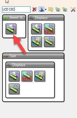
- Add "Liquid Crystal Display (LCD) - I2C" component
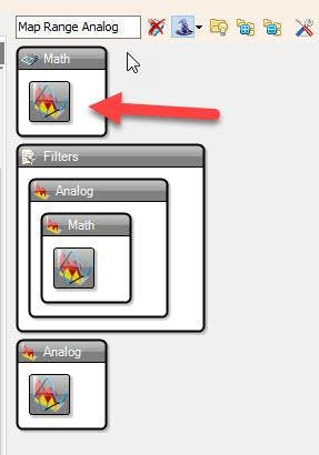
- Add "Map Range Analog" component
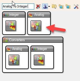
- Add "Analog To Integer" component
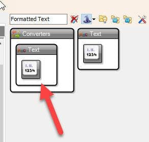
- Add "Formatted Text" component
1 / 7


- Select "LiquidCrystalDisplay1" and in the properties window set "Columns" to 20 and "Rows" to 4
Note: if you are using a different LCD that is not 20X4 then use Columns and Rows for that LCD
- Double click on the "LiquidCrystalDisplay1" and in the "Elements" window drag "Text Field" to the left and in the properties window set "Column" to 3, "Row" to 0, "Width" to 17, "Initial Value" to BATTERY LEVEL
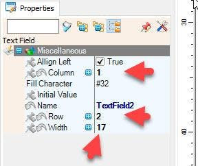
- Drag another "Text Field" to the left and in the properties window set "Column" to 1, "Row" to 2, "Width" to 17
- Close the "Elements" window
- Select "MapRange1" and in the properties window set "Output Range" > "Max" to 17 <<this will be equal to 17 LCD characters
- Select "FormattedText1" and in the properties window set "Text" to %0
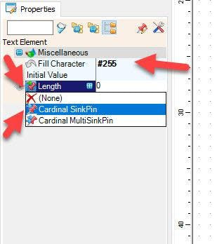
- Double click on the "FormattedText1" and in the "Elements" window drag "Text Element" to the left side and in the properties window set 'Fill Character" to #255 and select "Length" and click on the pin icon and select "Cardinal SinkPin"
- Close the "Elements" window
Note: if you are plan to use a different amount of LCD characters for the indicator, then change the number 17 in the "Text Field1" width and "MapRange1" >"Output Range" > "Max" to your number
Step 7: In Visuino Connect Components1 / 2
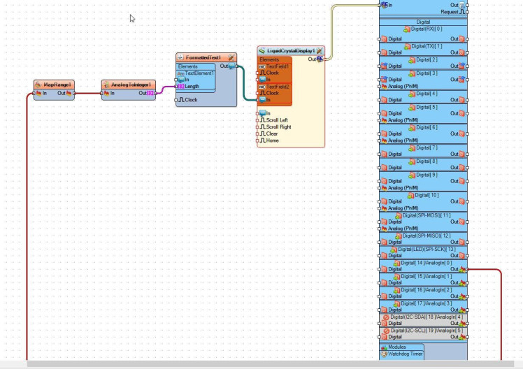

- Connect Arduino analog pin [0] to "MapRange1" pin [In]
- Connect "MapRange1" pin [Out] to "AnalogToInteger1" pin [In]
- Connect "AnalogToInteger1" pin [Out] to "FormattedText1" > "TextElement1" pin [Length]
- Connect "FormattedText1" pin [Out] to "LiquidCrystalDisplay1" > "Text Field2" pin [In]
- Connect "LiquidCrystalDisplay1" I2C pin [Out] to Arduino I2C pin [In]
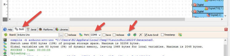
In Visuino, at the bottom click on the "Build" Tab, make sure the correct port is selected, then click on the "Compile/Build and Upload" button.
Step 9: PlayIf you power the Arduino module, the LCD will start to show the Value from the Analog Pin as a Battery Level, If you connected a potentiometer to the Analog Pin then you can change the position and see how it will affect the Indicator on the LCD Display.
Congratulations! You have completed your project with Visuino. Also attached is the Visuino project, that I created for this Tutorial, you can download it and open it in Visuino: https://www.visuino.eu
Schematics, diagrams and documents
Code
Credits
Related products


Leave your feedback...