
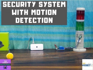
Security System With Motion Detection

Made by the lonely programmer / Environmental Sensing / Lights / Photos & Video / Security / IoT
About the project
The system is designed to detect intrusion (unauthorized entry) into a building or other area.
Project info
Difficulty: Moderate
Platforms: Digilent, Raspberry Pi
Estimated time: 1 hour
License: MIT license (MIT)
Items used in this project
Hardware components


Story
Why Did We Build This?
There is a lot of theft scenarios nowadays which causes a great loss to the owner. A recent incident at a popular jewellery shop urged me to do this project.
Robbery at jewellery shop

Robbery at jewellery shop
"A jewellery store in Tamil Nadu’s Tiruchirappalli district was burgled in the early hours of Wednesday morning after masked men gained entry into the store by drilling a hole in its wall. The incident took place at ####### Jewellery, a three-storeyed building near Chathiram bus Stand in Tiruchirappalli.
Diamond, Gold and Platinum jewellery worth 13 crore rupees were stolen from the store. I am satisfied with the way the investigation is being carried, the robbers will be caught soon" - Source from Indian Express
Idea ?
The system is designed to detect intrusion (unauthorized entry ) into a building or other area. This project can be used in residential, commercial, industrial, and military properties for protection against burglary or property damage, as well as personal protection against intruders
A compact, low profile project is attached to the wall of the area which has to be monitored. This project consists of a camera that will capture the image of the intruder and notify the owner.
To test the real-time scenario, we deployed it on one of the jewelry shops to test how possibly it could help them and the results were pretty affirmative.
Working of the ProjectHardware Build
First of all, I would like to thank KEMET and Hackster.io for supporting this project with an efficient and low profile pyro sensor. I really felt helpful to achieve some of the complex designs with this tiny sensor.
packed and sealed parcel

packed and sealed parcel
SS-430 Pyro sensor

SS-430 Pyro sensor
Step 1: Getting Started with Pyroelectric Proximity Infrared Sensors (Content from KEMET)
KEMET Electronics Pyroelectric Proximity Infrared Sensor Modules use the pyroelectric proximity effect of ceramic by absorbing infrared rays emitted from the human body. This detects the natural infrared signature produced by humans. It can detect infrared rays without using lenses, allowing a detection distance up to 2 meters. By adding a KEMET proprietary lens, the detection distance can be further improved up to 5 meters. The lens is available in three different colors, to enable some design flexibility. KEMET Electronics Pyroelectric Proximity Sensor Modules in the module solution are even easier to install with the driving being already included in the package, making it just "plug and sense".
KEMET Pyro Sensor

KEMET Pyro Sensor
FEATURES
- Reflow capable SMD configuration
- Lens not required
- Wide view angle up to ±60°
- Detection possible through glass or resin
- Low power consumption, down in the μA range
- Excellent radio wave performance in a high-frequency band
- Compact and low profile (5.0 x 4.8 x 1.7mm)
- Human presence detection sensing for energy-saving functions in a variety of applications
APPLICATIONS
- Contactless switching
- Office automation equipment
- Home appliances
- Lighting
- Display products
- Air-conditioners
- TVs
- PC monitors
- Rice cookers
- Smart toilets
We use the sensor with a white lens which gives a 74° view angle and the range up to 5m.
To learn more about the KEMET pyro sensor, do watch the webinar from hackster.io
Step 2: Burn Raspbian to the SD card
Raspbian is the Linux distribution of choice running on the Raspberry Pi. In this guide, we will be using the Lite version, but the Desktop version (which comes with a graphical environment) can be used as well.
- Download Etcher and install it.
- Connect an SD card reader with the SD card inside.
-
Open Etcher and select from your hard drive the Raspberry Pi
.imgor.zipfile you wish to write to the SD card. - Select the SD card you wish to write your image to.
- Review your selections and click 'Flash!' to begin writing data to the SD card
1 / 2 • Download Raspbian Stretch Lite

Download Raspbian Stretch Lite

Unzip it
Connect the device to your network
-
Enable SSH access by adding empty file
ssh, again placed at the root of thebootvolume on your SD card. - Insert the SD card into the Raspberry Pi. It will boot in roughly 20 seconds. You should now have SSH access to your Raspberry Pi. By default, its hostname will be raspberrypi.local.
On your computer, open a terminal window and type the following:
ssh pi@raspberrypi.localThe default password is raspberry

Step 3: Interfacing with Raspberry Pi (Project Motion Dashcam)
KEMET's PYROSENSOR - SS430
The Block Diagram of this circuit is given below.
Block Diagram

Block Diagram
To make these connections, I've used separate connectors for power, relay output, and sensor input. Each connector is soldered to the Raspberry Pi as shown below.
1 / 2 • Connector

Connector

Rapsberry Pi with Con
Since the output from the pyro sensor is a digital signal, we connect the KEMET pyro sensor to the GPIO Pin 15 of Raspberry Pi.
Raspberry Pi with SD card

Raspberry Pi with SD card
The Pinout of the SS-430 pyroelectric sensor is given below
SS-430 pinout

SS-430 pinout
The connection is made as shown below.
SS-430 ---> Raspberry Pi
Vcc (1) ---> +5V
Signal (4) ---> GPIO15
GND (5)---> GND
Sensor Connection

Sensor Connection
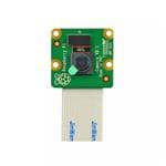
PI-CAMERA
The Pi-camera is connected to the CSI port of the Raspberry Pi.
Raspberry Pi Camera Module V2

Raspberry Pi Camera Module V2
Pi-cam to Raspberry Pi

Pi-cam to Raspberry Pi
RELAY BOARD
We connect the Buzzer and an Emergency light using a relay circuit to the GPIO pins 23 & 24 of the Raspberry Pi.
RELAY DRIVE CIRCUIT

RELAY DRIVE CIRCUIT
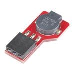
The Power Supply is used to deliver the power for the Status Light, Emergency Light, and the Alarm.
Power Supply

Power Supply
The Industrial grade Light Indicators and Buzzer are used to show the status and alert signal to the security (user).
Industrial grade Light Indicators

Industrial grade Light Indicators
Relay Board ---> Raspberry Pi
Vcc ---> +5V
IN1 (Secure Light)---> GPIO23
IN2 (AlertLight & Buzzer) ---> GPIO24
GND ---> GND
The Industrial grade Light Indicators and Buzzer are connected to the GPIOs of the Raspberry Pi.
1 / 2 • Sensor Connection

Sensor Connection

Power supply Connection
PUSH BUTTON
The Emergency reset button is connected to the GPIO pin 14 of the Raspberry Pi.
1 / 2 • Push Button

Push Button

Wires soldered to Button
Arcade Button connected to raspberry pi

Arcade Button connected to raspberry pi
The emergency button is used to turn off the alert manually by pressing it once.
The Overall connection is shown below.
Overall Connection

Overall Connection
Step 4: Code
GPIO of the Raspberry Pi can be accessed using the GPIO library which can be imported using the GPIO library.
The libraries such as RPi.GPIO and time are used in this project.
import RPi.GPIO as GPIO import timeThe GPIO pin is then configured to digital input using the following lines
sensorPIN = 15GPIO.setmode(GPIO.BCM)GPIO.setup(sensorPIN, GPIO.IN)GPIO Pin 15 is configured to use as digital input which reads for every 50ms. Whenever the intruder/human enters in the range, the sensor detects and produces the digital pulse.
while True: if GPIO.input(sensorPIN): # if sensorPIN == 1 print "Intruder Alert !!!" else: print "No intruder" time.sleep(0.05) # wait 50 millisecondsAlthough the above code worked, I had a few false triggering. After going through the documentation from KEMET, The SS-430 produces two output pulses of 200msec per detection. This can be interpreted by the Raspberry pi using the following code:
Timing Diagram from the webinar

Timing Diagram from the webinar
import RPi.GPIO as GPIOimport timesensorPIN = 15GPIO.setmode(GPIO.BCM)GPIO.setup(sensorPIN, GPIO.IN)pulse = 0PyroRead = 0IR_threshold = 198000IR_sensed = 0start_time = 0end_time = 0try: while True: while(IR_sensed < 2): start_time = time.time() GPIO.wait_for_edge(sensorPIN, GPIO.FALLING) GPIO.wait_for_edge(sensorPIN, GPIO.RISING) GPIO.wait_for_edge(sensorPIN, GPIO.FALLING) end_time = time.time() PyroRead = round((end_time - start_time)*1000000) print(PyroRead) if(PyroRead > IR_threshold): IR_sensed += 1 pulse = pulse + 1 print(pulse) print("Intruder Alert !!!") PyroRead = 0 IR_sensed = 0 time.sleep(1) # wait 1 secondfinally: print("clean up") # GPIO.cleanup([sensorPIN]) GPIO.cleanup() # cleanup all GPIONow the sensor can determine the presence of the human within the specified range and view angle.
Screenshot - sensor-test

Screenshot - sensor-test
After a lot of struggles and effort, I have created a library to interface KEMET's pyro sensor with the Raspberry Pi.
The picamera library is installed using the following command
sudo apt-get install python-picamera
installing picamera lib

installing picamera lib
Next, we interface the Raspberry Pi Camera Module V2 to the Raspberry Pi. We import picamera library to interface the camera with the raspberry pi. We have set the resolution of the camera at 1024 x 768 so that the images are captured at a lower resolution. This allows us to reduce memory usage and to send the images.
import picamerawith picamera.PiCamera() as camera: camera.resolution = (1024, 768)When the intruder is detected, the event is triggered and the system captures the images of the intruder. The images captured are stored in a folder with the timestamp attached to it.
with picamera.PiCamera() as camera: camera.resolution = (1024, 768) for filename in camera.capture_continuous('/home/pi/Intruder/img{timestamp:%H-%M-%S-%f}.jpg'):
Camera output and a screenshot of the directory

Camera output and a screenshot of the directory
From the above example, the picture of the intruder is captured by the device which has to be transmitted to the master (owner).
First, we add the Smtplib package allows us to set up the Gmail server. Install an SMTP service with the command
sudo apt-get install ssmtp
Screenshot - SMTP package

Screenshot - SMTP package
Make sure that Allow less secure apps setting is turned on for allowing Gmail SMTP Access Authentication.
SMTP - AUTH

SMTP - AUTH
import globimport smtplibimport osThese four modules are used to send the emails from a Raspberry Pi:
from email.mime.multipart import MIMEMultipartfrom email.mime.base import MIMEBasefrom email.mime.text import MIMETextfrom email.utils import formatdatefrom email import encodersWe need to add the receiver's email and sender's email address and password, in our case both, are the same email as shown below:
sender = 'x@gmail.com'password = ' Replace the pass 'receiver = 'x@gmail.com'By making several adjustments to the code, you can change the Subject, sender address, receiver address, and the content of the body. The images are sorted and the latest image is sent via Gmail (SMTP).
Screenshot of the Gmail

Screenshot of the Gmail
We have also added two relay circuit and a manual reset push button to the circuit. These are treated as normal GPIO to indicate or to inform the status of the theft alert using LED and Buzzers.
# Set pins 23, 24 to be an output pin and set initial value to low (high), since relay ckt is pull-down mechanismGreen = 23Red = 24GPIO.setup(Green, GPIO.OUT, initial=GPIO.HIGH) GPIO.setup(Red, GPIO.OUT, initial=GPIO.HIGH) # Set pin 14 to be an input pinreset_button = 14GPIO.setup(reset_button, GPIO.IN)while True: if GPIO.input(sensorPIN): # if sensorPIN == 1 GPIO.output(23, GPIO.HIGH) # Turn off Green GPIO.output(24, GPIO.LOW) # Turn on Red if !GPIO.input(reset_button): break else: GPIO.output(23, GPIO.LOW) # Turn on Green GPIO.output(24, GPIO.HIGH) # Turn off Red sleep(0.05) # wait 50 millisecondsStep 5: Enclosure
- I had used the raspberry pi zero enclosure for this project.
enclosure

enclosure
- A small section is needed to attach the SS-430 pyro sensor to the project. I have adhered the sensor to the Indicator firmly as shown below.
Indicator with SS-430

Indicator with SS-430
- Make sure that the required wires/connects are soldered to the raspberry pi. This is a crucial part to meet the size of the device. I have used the terminal block connector to make the common connections. One end of the wires is soldered to the Raspberry Pi.
Cables soldered to RPi & End of the wires to terminal block

Cables soldered to RPi & End of the wires to terminal block
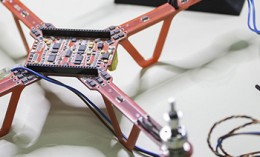
- Now Insert the device inside the enclosure and It would look something like this
1 / 3 • Final Setup1

Final Setup1

Final Setup2

Sensor attached to a Glass surface
Voila! The connection is done and we are equipped to test it.
Working of the Project ?
To test the real-time scenario, we deployed it on one of the jewelry shops to test how possibly it could help them and the results were pretty affirmative.
If you faced any issues in building this project, feel free to ask me. Please do suggest new projects that you want me to do next.
Give a thumbs up if it really helped you and do follow my channel for interesting projects. :)
Share this video if you like.
Happy to have you subscribed: https://www.youtube.com/c/rahulkhanna24june?sub_confirmation=1
Thanks for reading!
Schematics, diagrams and documents
Code
Credits
the lonely programmer
Passionate Techie ! Robotics | Electronics | Programming Hey Geek! If you are in search of electronics projects, Arduino based projects or any Micro-controller based projects, this channel is for you. In this channel, we build electronics projects using the impressive and low-cost boards that are available today. If you are a maker or if you want to learn how to make your own Arduino projects and other interesting Robots, do subscribe the channel to be a part of this community. We develop our own hardware and software projects and will try to build something new. Don’t worry if you don’t know how to program. I'll share the algorithm if you face any difficulties.
Leave your feedback...