
Robot Arm That Mimics Your Arm Movements

Made by bitluni / 3D Printing / Robotics / Sensors
About the project
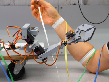
This project shows 3D printed robot arm that mimics your arm movements. The arm motion is sensed using accelerometers and a digital compass.
Project info
Difficulty: Moderate
Platforms: Arduino
Estimated time: 3 days
License: GNU General Public License, version 3 or later (GPL3+)
Items used in this project
Hardware components


View all
Story
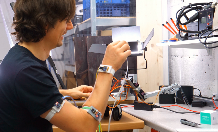
The robot arm project is a proof of concept if a simple 3D-printed driven by affordable servo motors can be controlled by accelerometers and a magnetometer attached to the controlling persons arm. The person need to learn using any input devices just perform the movement that should be reflected by the robot. A use case could be to perform manual tasks remotely in inaccessible or dangerous areas.
See the robot arm in action:
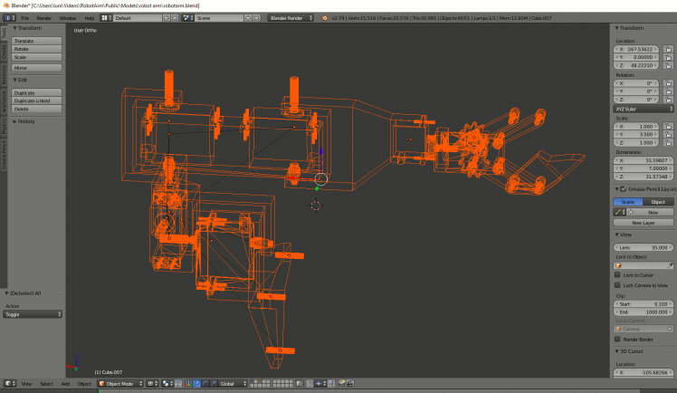
Mechanical Design
The CAD design was done in blender since I'm most familiar with it and it's free for everyone forwever.
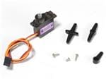
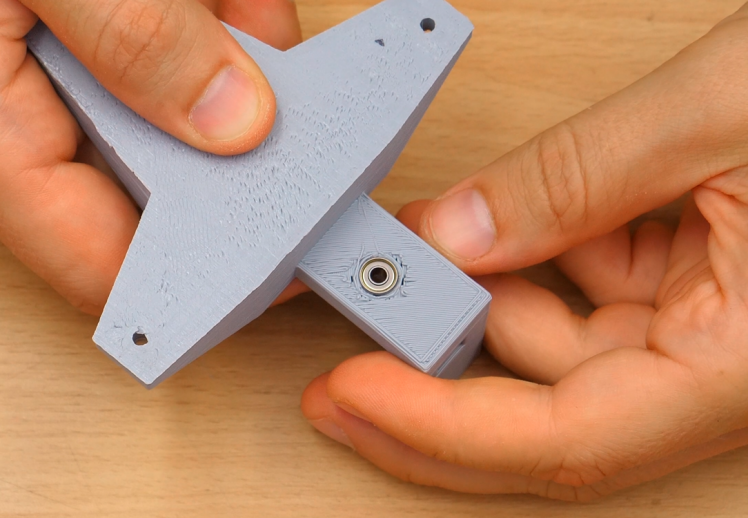
The most parts are constructed using boolean modifiers. Since the servos have only the rotor on one side the axis has to be extended to the other side. This is done using a ball bearing and a 3mm bolt with a lock nut which sits in the bearing.
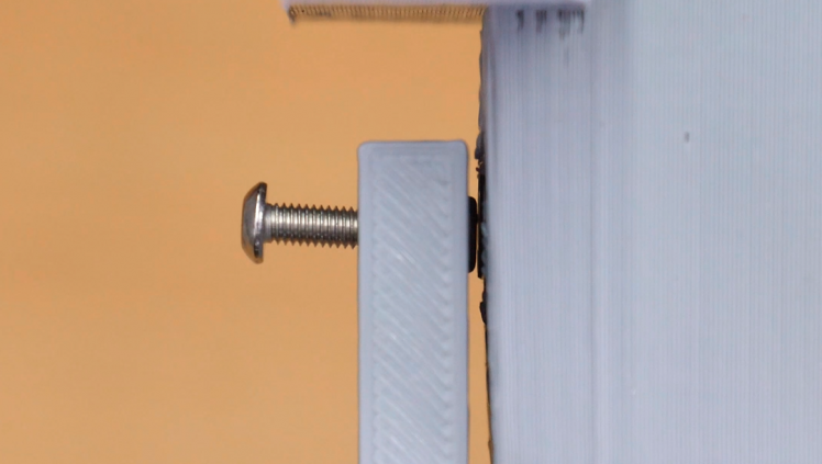
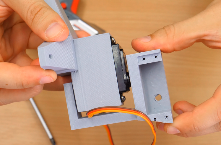
Fixing the servo directly to the part sometimes results the bolt to loosen. You might want to use lock tight or implement some kind of keyway to the servo rotor. Apart from that the assembly of the arm is quite straight forward and can be checked up in the blender file if needed.
The Sensors
There are four sensors used. Three of these are responsible for the arm movements and one for the gripper.
The servos in the upper, lower arm and the wrist are capable of measuring the acceleration. Additionally, the digital compass of the sensor at the wrist is used.
The accelerometers measure the orientation of the limbs relative to the gravity vectors. These orientations determine the angles of the servo motors.
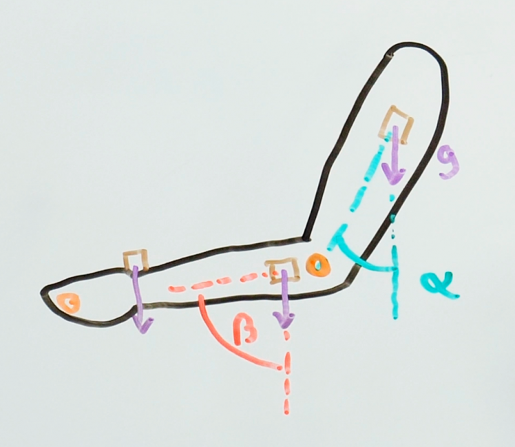
Since regular movement also creates acceleration the trajectory of the robot arm will differ at higher movement speeds.
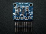
The magnetometer (compass) is used to measure the arm yaw. The measured position on the start up of the micro controller is measured and taken as the reference forward direction later. The compass vector is taken at the wrist and applied to a should servo which rotates the complete arm.
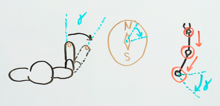
Since the orientation of the wrist sensor needs to be subtracted from the compass vector to get the absolute world orientation, all transformations from shoulder to wrist are back transformed using matrices. This happens in the calculateAngles method of the sketch.
- //calculate the absolute compass vector
- float a1 = -atan2(-sensors[1][1], -sensors[1][0]);
- Matrix r0 = Matrix::rotation(-a1, 0, 1, 0);
- float a2 = atan2(sensors[2][1], sensors[2][2]);
- Matrix r1 = Matrix::rotation(angles[4], 1, 0, 0);
- Vector v = r0 * r1 * sensors[3];
- v[2] = 0;
- v.normalize();
- compass0 = v;
The Wiring
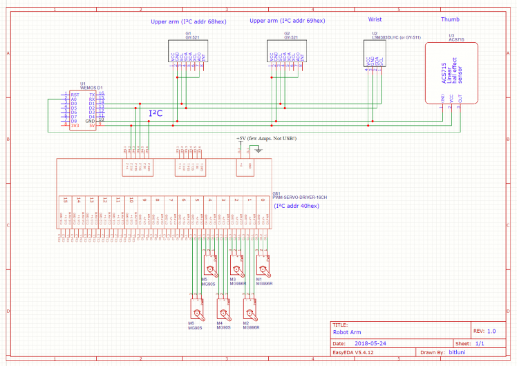
Almost all communication is done using I²C. To be able to address two GY-521 sensors at once they have two different addresses assigned by wiring either GND or VCC to the ADD pin of the sensor boards.
The I²C is a bit limited in signal strength. You might want to add additional pull-up resistors to SDA and SCL. All sensor boards are powered by 5V since they have their own 3.3V regulators. The GY-511 board I am using also has an 3.3V pin which changes the pin order.. be careful to connect the right pin to 5V if you are building an adapter board like me.
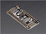
The power supply that's connected to the PWM board screw connectors should be able to apply several amps since quite some forces can occur with 6 active servos. Your USB will be overloaded for sure if you don't use an additional supply.
The Code
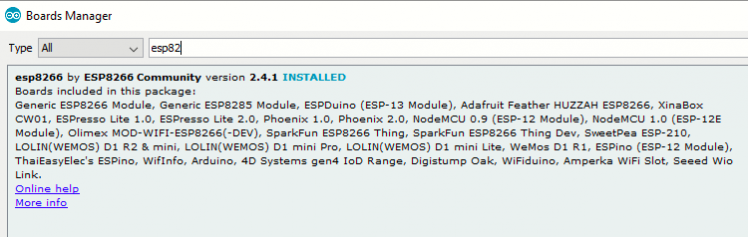
The code is uploaded to the WeMos D1 Mini micro controller (esp8266 core) from the Arduino IDE.
Support for the ESP8266 is provided by the corresponding extension from the bards manager
For the support of the compass the libraries
- Adafruit_Sensor
- Adafruit_LSM303
are needed and for the PWM extension board the library
- Adafruit_PWMServoDriver
These can be found in the library manager from the Sketch -> Include Library.. menu.
The code can be found in the github repository and should be well commented to provide a good orientation.
Have fun!
I hope you are inspired! If you have suggestions how to improve this idea please share it with us! I would also love to see any similar builds from you!
CAD, enclosures and custom parts
Code
Credits
Related products


Leave your feedback...