
Remotely Controlled Plant Watering System Using nRF7002 Dk

Made by knaveen / Environmental Sensing / Home Automation / Plants / Sensors / IoT
About the project
An IoT-based device that sends indoor plant status over MQTT and can be watered automatically or remotely.
Project info
Difficulty: Moderate
Platforms: Home Assistant, M5Stack, MQTT, Nordic Semiconductor
Estimated time: 5 hours
License: GNU General Public License, version 3 or later (GPL3+)
Items used in this project
Hardware components

Story
Setting up an indoor watering system doesn’t have to be complicated and is so worthwhile when you’re finished. Plant irrigation indoors saves time that you can devote to other areas of your plant’s needs. But how about getting to know your plant status and watering them properly? Every plant species has its specific watering needs. If you’ve ever drowned an indoor plant, you’re not alone. In this project, we are going to make a system that allows plants to get watered automatically or remotely controlled by monitoring the soil moisture level.
Hardware Setup
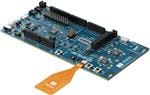
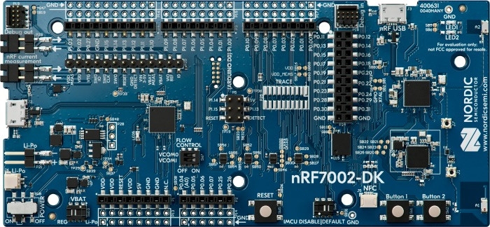
To send the plant status and control the watering system, we are using a Nordic nRF7002 DK, a development kit for the nRF7002 Wi-Fi 6 Companion IC, which has an nRF5340 multi-protocol System-on-Chip (SoC) as a host processor for the nRF7002.
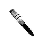
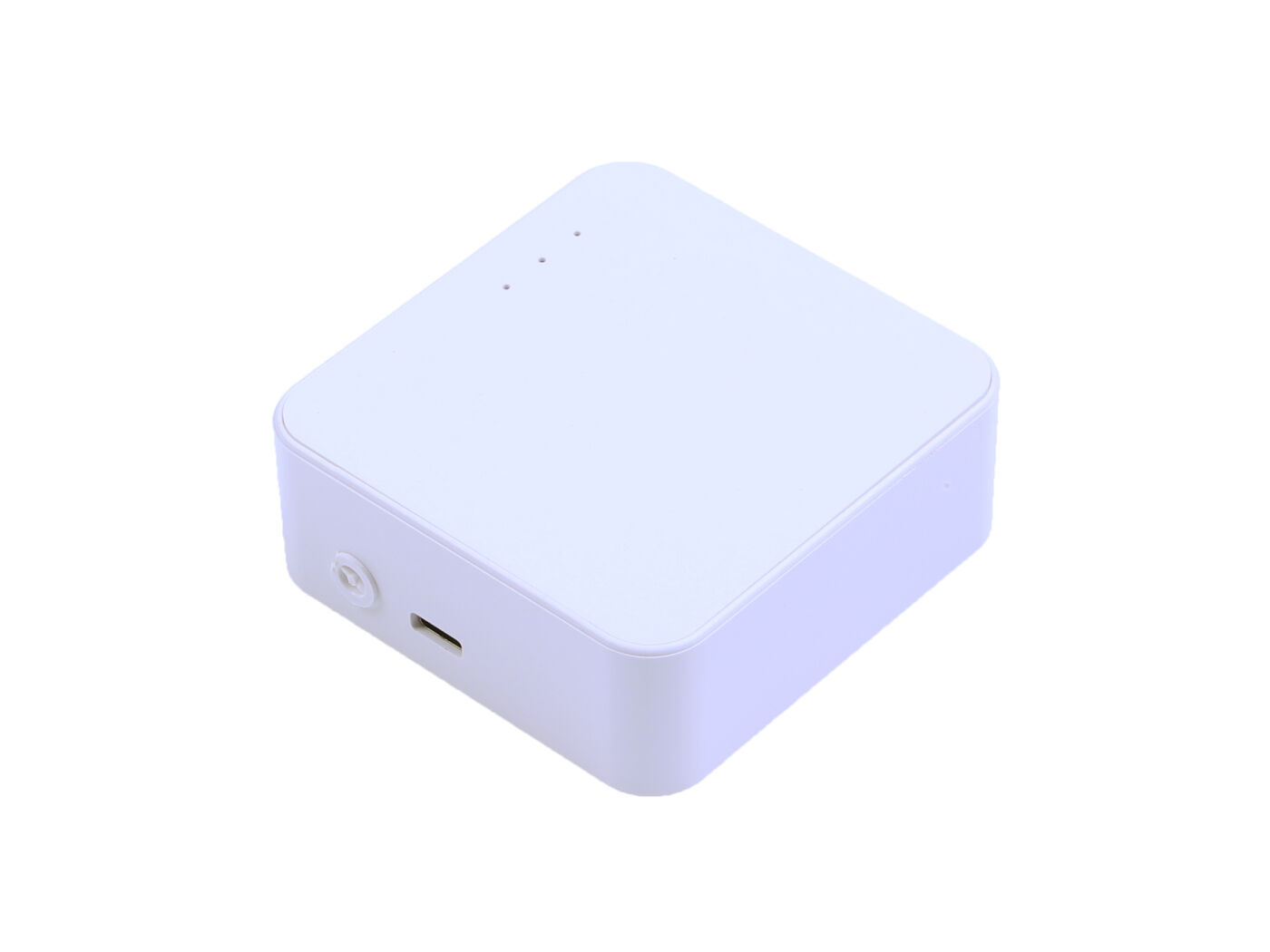
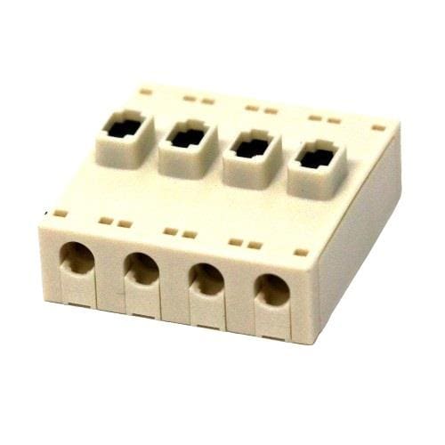
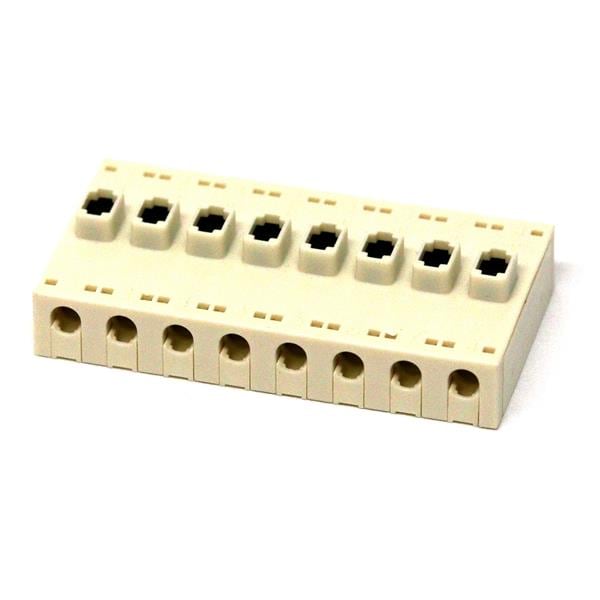
We are using an M5Stack Watering unit which has a capacitive soil moisture sensor and a water pump. The water pump has a 5W rating so we will be powering it from an external power supply. To connect a USB power bank, we are using an M5Stack USB TypeC2Grove Unit.
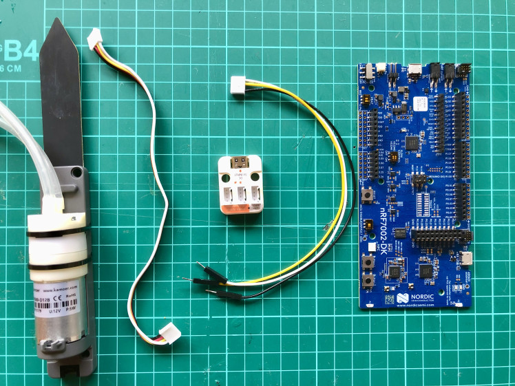
The nRF7002 DK runs at 1.8 V but the Watering Unit soil moisture analog output is 0 - 3.3V as mentioned in the datasheet so we need a logic level shifter to interface it with the nRF7002 DK header pins. We tested the Watering Unit soil moisture analog output with an Oscilloscope and found that it never exceeds 1.8 V at extreme conditions. So we are not using a logic level shifter for this specific sensor but please check your sensor voltage before interfacing it with the nRF7002 DK otherwise it may cause unexpected results or can damage the MCU.
The connection schematics are given below.

Setup Development Environment
For the development work, I am using macOS but the setup process is similar for all platforms. First, we need to download nRF connect for Desktop from here:
https://www.nordicsemi.com/Software-and-tools/Development-Tools/nRF-Connect-for-desktop/Download.
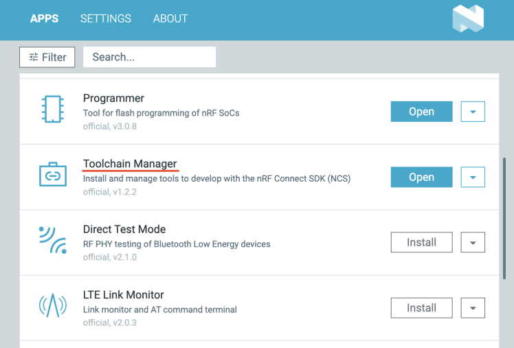
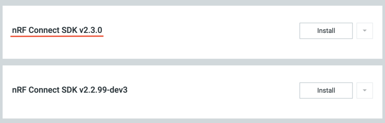
The nRF Connect for Desktop is a cross-platform tool that enables testing and development with nRF7002 DK. Please follow the installation guide in the link above. When the installation is completed, open the app and click on the Toolchain Manager and choose nRF Connect SDK v2.3.
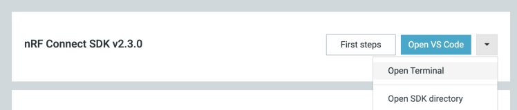
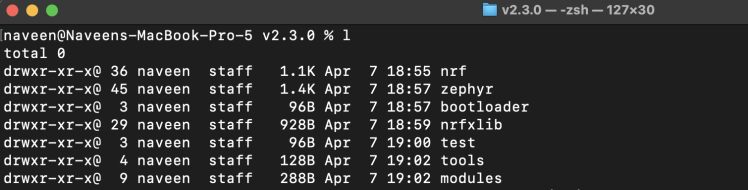
By default, the SDK is installed in the /opt/nordic/ncs directory in macOS. After installation, click on the Open Terminal which opens up a command line terminal with all environment variables initialized to get started quickly with the development.
Application Development
We are using the MQTT sample code from the nordic/ncs/v2.3.0/nrf/samples/net/mqtt from the SDK. MQTT is a messaging protocol for the Internet of Things (IoT) which is designed as an extremely lightweight publish/subscribe messaging transport that is ideal for connecting remote devices with minimal network bandwidth. The MQTT sample communicates with an MQTT broker over Wi-Fi using the nRF7002 DK. We will be using the Home Assistant, an open-source software for home automation, for the MQTT broker services and dashboard to display the application user interface.
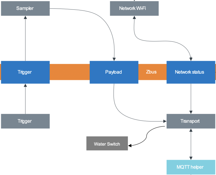
The sample has a modular structure, where each module has a defined scope of responsibility. The communication between modules is handled by the Zephyr message bus (zbus) using messages that are passed over channels. If a module has internal state handling, it is implemented using the Zephyr State Machine Framework. The default sample has 4 main modules: Network WiFI, Sampler, Trigger, and Transport. The Sampler module has been modified to sample soil moisture data over the ADC channel. The Trigger module triggers the sampler to publish the data at configurable intervals. To control the water pump, the Water Switch module has been added to the modules stack that receives the subscription payload from the Transport module. The following figure illustrates the relationship between modules, channels, and network stacks in the sample.
To enable ADC and GPIO support we have added the following lines to the prj.conf file.
- # ADC
- CONFIG_ADC=y
- CONFIG_ADC_ASYNC=y
- CONFIG_ADC_LOG_LEVEL_INF=y
- # Water pump Digital Pin
- CONFIG_GPIO=y
Also, we have created an overlay file nrf7002dk_nrf5340_cpuapp.overlay with the following contents.
- &adc {
- status = "okay";
- };
The Water Switch module (src/modules/water_switch) code is given below.
- #include <zephyr/kernel.h>
- #include <zephyr/logging/log.h>
- #include <zephyr/zbus/zbus.h>
- #include <zephyr/drivers/gpio.h>
- #include "message_channel.h"
- /* Register log module */
- LOG_MODULE_REGISTER(water_switch);
- #define WATER_PUMP_PIN 10 // P1.10 (D8)
- const static struct device *digital_pin_dev;
- static bool configured = false;
- void configure()
- {
- digital_pin_dev = DEVICE_DT_GET(DT_NODELABEL(gpio1));
- if (!digital_pin_dev) {
- LOG_ERR("device gpio1 not foundn");
- return;
- }
- if (!device_is_ready(digital_pin_dev)) {
- LOG_ERR("GPIO controller not ready");
- return;
- }
- gpio_pin_configure(digital_pin_dev, WATER_PUMP_PIN, GPIO_OUTPUT);
- }
- void water_switch_callback(const struct zbus_channel *chan)
- {
- int err = 0;
- const enum water_switch_status *status;
- if (&WATER_SWITCH_CHAN == chan) {
- if (!configured) {
- configure();
- configured = true;
- LOG_INF("GPIO pin configured");
- }
- /* Get network status from channel. */
- status = zbus_chan_const_msg(chan);
- LOG_INF("status = %d", *status);
- switch (*status) {
- case SWITCH_OFF:
- err = gpio_pin_set(digital_pin_dev, WATER_PUMP_PIN, 0);
- if (err) {
- LOG_ERR("digital pin, error: %d", err);
- } else {
- LOG_INF("SWITCH_OFF: %d", err);
- }
- break;
- case SWITCH_ON:
- err = gpio_pin_set(digital_pin_dev, WATER_PUMP_PIN, 1);
- if (err) {
- LOG_ERR("digital pin, error: %d", err);
- } else {
- LOG_INF("SWITCH_ON: %d", err);
- }
- break;
- default:
- LOG_ERR("Unknown event: %d", *status);
- break;
- }
- }
- }
- /* Register listener - water_switch_callback will be called everytime a channel that the module listens on
- * receives a new message.
- */
- ZBUS_LISTENER_DEFINE(water_switch, water_switch_callback);
In the src/modules/transport file, we have modified the on_mqtt_publish function to pass the subscription call to the Water Switch module over the Zbus channel.
- static void on_mqtt_publish(struct mqtt_helper_buf topic, struct mqtt_helper_buf payload)
- {
- LOG_INF("Received payload: %.*s on topic: [%.*s]", payload.size,
- payload.ptr,
- topic.size,
- topic.ptr);
- enum water_switch_status status;
- if (payload.size == 1) {
- if (payload.ptr[0] == 48) {
- LOG_INF("SWITCH_OFF");
- status = SWITCH_OFF;
- }
- if (payload.ptr[0] == 49) {
- LOG_INF("SWITCH_ON");
- status = SWITCH_ON;
- }
- }
- int err = zbus_chan_pub(&WATER_SWITCH_CHAN, &status, K_SECONDS(1));
- if (err) {
- LOG_ERR("zbus_chan_pub, error: %d", err);
- SEND_FATAL_ERROR();
- }
- }
Setup Home Assistant
There are many ways to install the Home Assistant Operating System. Please follow the instructions at the link below.
https://www.home-assistant.io/installation/
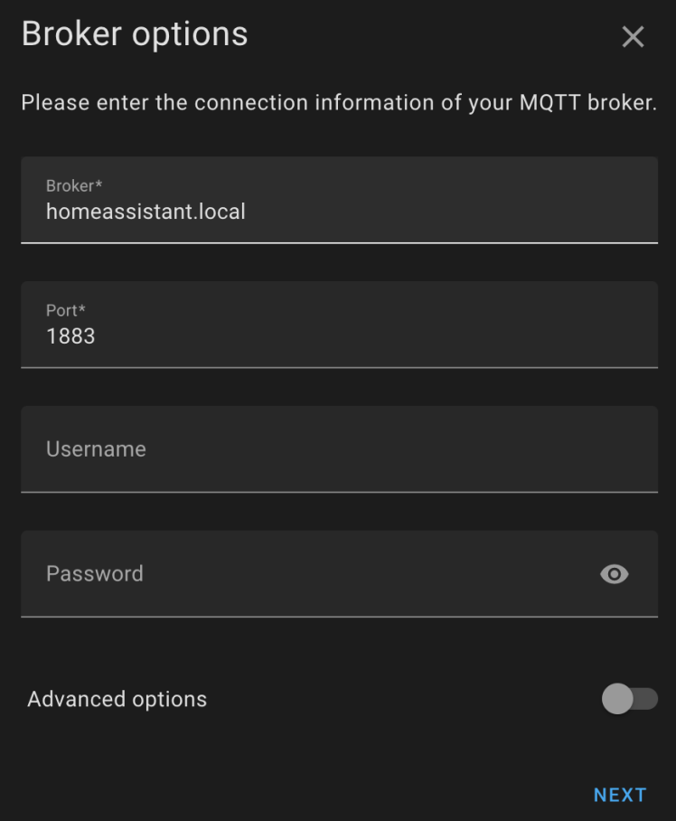
I am using a Home Assistant Virtual Machine on a macOS host. After starting up the VM instance, we can access the Home Assistant portal using a web browser at http://homeassistant.local:8123. The Home Assistant provides a few options to set up an MQTT broker. I am using EMQX which can be installed by searching at Settings > Add-ons > Add-on Store. Another option is to install Mosquitto but I had to install EMQX because it allows me to configure the broker without any username/password. I couldn't find an easy way to provide a username/password in the sample MQTT application so I chose EMQX. After installing EMQX, we need to set up an MQTT integration by going to Settings > Devices & Services > Add Integration and searching for MQTT. After adding the MQTT integration click on Configure and set the values as shown below.
Also, we always need to restart the Home Assistant after any configuration changes by clicking Settings > Top Right Kebab menu > Restart Home Assistant.
We have added two UI cards in the Overview > Dashboard, a Gauge card for displaying the soil moisture sensor data and a Button card for controlling the water pump. We need to configure the card entity using configuration files that can be accessed and edited using the SAMBA share at the host computer. The following configuration is added to the configuration.yaml.
- mqtt:
- sensor:
- - name: "Soil Moisture"
- state_topic: "/myhome/plant/status"
- unit_of_measurement: "%"
- value_template: "{{ value_json.soil_moisture | float }}"
- switch:
- - name: "Watering Switch"
- command_topic: "/myhome/plant/watering"
- qos: 1
- payload_on: 1
- payload_off: 0
- retain: true
We have added a configuration in the config/automations.yaml file for automatically switching off the Water Switch after 5 seconds of manual click and triggering the switch automatically if soil moisture is below 35%.
- - trigger:
- - platform: state
- entity_id: switch.watering_switch
- to: "on"
- for:
- milliseconds: 5000
- action:
- service: switch.turn_off
- target:
- entity_id: switch.watering_switch
- - trigger:
- - platform: numeric_state
- entity_id: sensor.soil_moisture
- below: 35
- action:
- service: switch.turn_on
- target:
- entity_id: switch.watering_switch
Again, we would need to restart the Home assistant to load the configuration.
The dashboard looks as below.

Build and flash the firmware
First, open the terminal using the Toolchain manager as described in the Setup Development Environment section and clone the GitHub repository.
- $ git clone https://github.com/metanav/nRF7002_DK_Indoor_Plant_Watering_System.git
- $ cd nRF7002_DK_Indoor_Plant_Watering_System
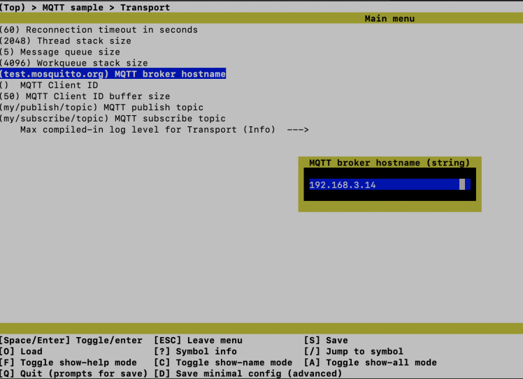
To configure the WiFi credential and the MQTT broker hostname, we need to execute the command below.
- $ west build -b nrf7002dk_nrf5340_cpuapp -t menuconfig
It will open up a console-based UI where we can find and set values for the required parameters.
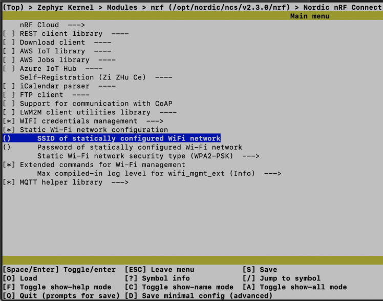
Similarly, we can set the MQTT broker hostname/IP address, publish topic, and subscribe topic as shown in the image below.
Now connect the nRF7002 DK to the computer using a USB cable and execute the command below to build and flash the firmware.
- $ west build -b nrf7002dk_nrf5340_cpuapp
- $ west flash
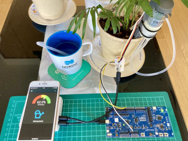
Demo
For the demo, the nRF7002 DK and the Watering unit are powered by a power bank. The Home Assistant can be accessed using a mobile phone browser. Although this project is developed using a home network and cannot be accessed outside the network but using the Home Assistant Cloud we can access it from outside.
Conclusion
This project showcases the low-powered and seamless WiFi connectivity capabilities of the nRF7002 DK for battery-powered IoT-based home automation projects.
Schematics, diagrams and documents
Code
Credits
Related products


Leave your feedback...