
Remote Wi-fi Dht11 Temperature & Humidity Lcd Display

About the project
Displaying DHT11 Temperature and Humidity remotely over Wi-Fi with 2 ESP8266 made easy!
Items used in this project
Hardware components

Software apps and online services
Story
ESP8266 modules are great low cost stand alone controllers with built in Wi-Fi, and I already made a simple Blink Tutorial with ESP8266 NodeMCU module.
The advantage of the ESP8266 over Arduino and other controllers is the built in Wi-Fi. In this Tutorial I will show you how with the help of Visuino you can use two ESP8266 modules to make a remote LCD Display for Temperature and Humidity DHT11 sensor.
In the Tutorial , I will use 2 NodeMCU modules. One version 0.9, and the other 1.0. The NodeMCU are the easiest way to program and experiment with ESP8266 controllers. This Tutorial however can easily be done with other modules, and the Sensor module can even use ESP-01 module as it needs only one GPIO pin to connect to the DHT11 sensor.
Step 1: Components
1 / 2 • Picture 1

Picture 1

Picture 2
- 2X NodeMCU ESP8266 boards (I used both NodeMCU 0.9, and NodeMCU 1.0 versions, but any other combination, or even stand alone ESP-12 will work)
- One DHT11 Sensor module I got from this cheap 37 sensors set
- One I2C 16x2 LCD Display (Back side of the LCD with the I2C adapter showed on Picture 2)
- 7X Female-Female jumper wires
1 / 4 • Picture 1

Picture 1

Picture 2

Picture 3

Picture 4
- Connect Power (Red wire), Ground (Black wire), and Data (Gray wire) to the DHT11 Module (Picture 1 shows 2 different types of DHT11 sensor modules. As you can see the pins may differ, so connect carefully!)
- Connect the other end of the Ground wire (Black wire) to the Ground pin of the ESP8266 module (Picture 2)
- Connect the other end of the Power wire (Red wire) to the 3.3V Power pin of the ESP8266 module (Picture 2)
- Connect the other end of the Data wire (Gray wire) to the Digital pin 2 of the ESP8266 module (Picture 3)
- Picture 4 shows where are the Ground, 3.3V Power, and Digital 2 pins of the NodeMCU 0.9
1 / 4 • Picture 1

Picture 1

Picture 2

Picture 3

Picture 4
- Connect Ground (Black wire), Power (Red wire), SDA (Green wire), and SCL (Yellow wire) to the LCD Module (Picture 1)
- Connect the other end of the SCL wire (Yellow wire) to SCL/Digital pin 1 of the ESP8266 NodeMCU board (Picture 2)
- Connect the other end of the SDA wire (Green wire) to SDA/Digital pin 2 of the ESP8266 NodeMCU board (Picture 2)
- Connect the other end of the Ground wire (Black wire) to the Ground pin of the ESP8266 NodeMCUboard (Picture 3)
- Connect the other end of the Power wire (Red wire) to the 5V (Called "Vin" in version 1.0) Power pin of the ESP8266 NodeMCU board (Picture 3)
- Picture 4 shows where are the Ground, 5V (Vin) Power, Digital 1, and Digital 2 pins of the NodeMCU 1.0
1 / 2 • Picture 1

Picture 1

Picture 2
To start programming the Arduino, you will need to have the Arduino IDE installed from here: http://www.arduino.cc.
Please be aware that there are some critical bugs in Arduino IDE 1.6.6.
Make sure that you install 1.6.7 or higher, otherwise this Tutorial will not work!
If you have not done follow the steps in this Tutorial to setup the Arduino IDE to program ESP 8266!
The Visuino: https://www.visuino.com also needs to be installed.
- Click on the "Tools" button on the Arduino component (Picture 1) in Visuino
- When the dialog appears, select "NodeMCU ESP-12" as shown on Picture 2
1 / 3 • Picture 1

Picture 1

Picture 2

Picture 3
- In the Object Inspector, expand the "Modules" property, then the "WiFi" sub property, then the "AccessPoint" sub property (Picture 1)
- Set the value of the "SSID" sub property of the "AccessPoint", to “Thermometer” (Picture 1)
To make sure the Access Point will be on the 200.200.200.X subnet, we need to assign a fixed address.
- In the Object Inspector, expand the "Config" sub property of the "AccessPoint" property (Picture 2)
- Set the value of the “Enabled” sub property of the Config to “True” (Picture 2)
- Set the value of the “IP” sub property to "200.200.200.100" (Picture 3)
1 / 4 • Picture 1

Picture 1

Picture 2

Picture 3

Picture 4
Next we need to add an UDP socket for the communication.
- In the Object Inspector, click on the "..." button next to the value of the "Sockets" sub property of the "WiFi" property (Picture 1)
- In the Sockets editor select “UDP Socket” on the right, and then click on the "" button on the left (Picture 2)
- In the Object Inspector, set the value “RemoteIPAddress” property to “200.200.200.200” (Picture 3) – this is the fixed IP address that we will assign to the other module later on
- In the Object Inspector set the value of the “RemotePort” to “8888” (Picture 4)
1 / 2 • Picture 1

Picture 1

Picture 2
- Type "dht" in the Filter box of the Component Toolbox then select the "Humidity and Thermometer DHT11/21/22/AM2301" component (Picture 1), and drop it in the design area
- Connect the "Sensor" pin of the HumidityThermometer1 component to the "Digital" input pin of the "Digital[ 2 ]" channel of the "NodeMCU ESP-12" component (Picture 4)
1 / 4 • Picture 1

Picture 1

Picture 2

Picture 3

Picture 4
We need to send a packet of 2 analog values. To do this we will make a structure with 2 analog values and will send it over the UDP socket.
- Type "stru" in the Filter box of the Component Toolbox then select the "Make Structure" component (Picture 1), and drop it in the design area
- Click on the "Tools" button (Picture 2) to open the "Elements" editor (Picture 3)
- In the "Elements" editor select the “Analog” element on the right, and then click 2 times on the "" button on the left (Picture 3) to add 2 Analog elements (Picture 4)
- Close the "Elements" editor.
1 / 3 • Picture 1

Picture 1

Picture 2

Picture 3
- Connect the “Temperature” pin of the HumidityThermometer1 component to the “In” pin of the “Elements.Analog1” element of the MakeStructure1 component (Picture 1)
- Connect the “Humidity” pin of the HumidityThermometer1 component to the “In” pin of the “Elements.Analog2” element of the MakeStructure1 component (Picture 2)
- Connect the “Out” pin of the MakeStructure1 component to the “In” pin of the "Modules.WiFi.Sockets.UDPSocket1” of the “NodeMCU ESP-12” component (Picture 3)
1 / 2 • Picture 1

Picture 1

Picture 2
The project can be used as it is, but if you run it it will overwhelm the network with UDP packets, as it will keep sending thermometer readings very fast one after another. It is better to read the thermometer only once a second. The Thermometer component has a “Clock” pin, that can be used to control when the thermometer will perform a reading and send the value to the socket. We will use a Clock Generator component to control the Thermometer.
- Type "clo" in the Filter box of the Component Toolbox then select the "Clock Generator" component (Picture 1), and drop it in the design area
- Connect the "Out" pin of the ClockGenerator1 component to the "Clock" input pin of the HumidityThermometer1 component (Picture 2)
1 / 2 • Picture 1

Picture 1

Picture 2
- In Visuino, Press F9 or click on the button shown on Picture 1 to generate the Arduino code, and open the Arduino IDE
- Connect the first NodeMCU module (The one with the DHT11) with USB cable to the computer
- Select the board type and serial port as I have shown you in this Tutorial
- Make sure you have installed the latest staging version of the ESP support! The stable release does not have some of the latest features, and you will have errors when you try to compile!
- In the Arduino IDE, click on the Upload button, to compile and upload the code (Picture 2)
1 / 5 • Picture 1

Picture 1

Picture 2

Picture 3

Picture 4

Picture 5
Now lets program the Display module.
- Start new project.
- Click on the "Tools" button on the Arduino component, and when the dialog appears, select "NodeMCU ESP-12" as you did in Step 4 for the Thermometer module
Next we need to configure the module to connect to the Access Point of the Thermometer module, and use a fixed IP Address of 200.200.200.200
- In the Object Inspector, expand the “Modules” property, then the “WiFi” sub property, then the “AccessPoints” sub property, and click on the "..." button next to its value (Picture 1)
- In the "AccessPoins" editor, select “WiFi Access Point”, and then click on the "" button on the left, to add the access point (Picture 2)
- In the Object Inspector, set the value of the "SSID" property to “Thermometer” (Picture 3)
- In the Object Inspector, expand the “Config” property, and set the value of the “Enabled” sub property to “True” (Picture 4)
- In the Object Inspector, set the value of the “IP” sub property to “200.200.200.200” (Picture 5)
1 / 3 • Picture 1

Picture 1

Picture 2

Picture 3
Next we need to add an UDP socket for the communication.
- In the Object Inspector, click on the "..." button next to the value of the "Sockets" sub property of the WiFi (Picture 1)
- In the Sockets editor select “UDP Socket” on the right, and then click on the "" button on the left (Picture 2)
- In the Object Inspector, set the value “RemoteIPAddress” property to “200.200.200.200” (Picture 3)
- In the Object Inspector set the value of the “Port” to “8888” (Picture 4)
- Close the "Sockets" dialog
1 / 6 • Picture 1

Picture 1

Picture 2

Picture 3

Picture 4

Picture 5
- Type "lcd" in the Filter box of the Component Toolbox then select the "Liquid Crystal Display (LCD) - I2C" component (Picture 1), and drop it in the design area
- Click on the "Tools" button (Picture 2) to open the "Elements" editor (Picture 3)
We will add a Text field with the description of the value, and Analog field to display the value for the Temperature and Humidity values. First we will add Description and value fields for the Temperature:
- Add Text field for the Temperature description text by select the "Text Field" in the right window of the "Elements" editor, and clicking on the "" button (Picture 3)
- In the Object Inspector set the "InitialValue" property of the element to "Temp:" (Picture 4) - This will specify the text to be displayed
- Add Analog field for the Temperature value by selecting the "Analog Field" in the right window of the "Elements" editor, and clicking on the "" button (Picture 5)
- In the Object Inspector set the "Column" property of the element to "10"(Picture 6) - This will specify the staring column of the field
1 / 6 • Picture 1

Picture 1

Picture 2

Picture 3

Picture 4

Picture 5

Picture 6
Next we will repeat the same steps for the Humidity:
- Add Text field for the Humidity description text selecting the "Text Field" in the right window of the "Elements" editor, and clicking on the "" button (Picture 1)
- In the Object Inspector set the "InitialValue" property of the element to "Humidity:" (Picture 2)
- In the Object Inspector set the "Row" property of the element to "1" (Picture 3) - This will specify that the field will be shown in the second row of the Display
- Add Analog field for the Humidity value by selecting the "Analog Field" in the right window of the "Elements" editor, and clicking on the "" button (Picture 4)
- In the Object Inspector set the "Column" property of the element to "10"(Picture 5)
- In the Object Inspector set the "Row" property of the element to "1" (Picture 6)
1 / 4 • Picture 1

Picture 1

Picture 2

Picture 3

Picture 4
The Thermometer module sends the temperature and humidity in binary floating point form as a structure. We need to decode it properly. For this we need a “Split Structure” component with 2 “Analog” elements in it.
- Type "split" in the Filter box of the Component Toolbox then select the "Split Structure" component (Picture 1), and drop it in the design area
- Click on the "Tools" button (Picture 2) to open the Elements editor (Picture 3)
- In the "Elements" editor select the “Analog” element, and then click 2 times on the "" button (Picture 3) to add 2 Analog elements (Picture 4)
- Close the Elements editor
1 / 5 • Picture 1

Picture 1

Picture 2

Picture 3

Picture 4

Picture 5
- Connect the "Out" pin of the "Elements.Analog1" of the SplitStructure1 component to the "In" pin of the "Elements.AnalogField1" element of the LiquidCrystalDisplay1 component (Picture 1)
- Connect the "Out" pin of the "Elements.Analog2" of the SplitStructure1 component to the "In" pin of the "Elements.AnalogField2" element of the LiquidCrystalDisplay1 component (Picture 2)
- Connect the "Out" pin of the LiquidCrystalDisplay1 component to the to the "In" pin of the I2C channel of the “NodeMCU ESP-12” component (Picture 3)
- Connect the “Out” pin of the “Modules.WiFi.Sockets.UDPSocket1” (Picture 4) of the “NodeMCU ESP-12” component, to the “In” pin of the SplitStructure1 component (Picture 5)
1 / 2 • Picture 1

Picture 1

Picture 2
- In Visuino, Press F9 or click on the button shown on Picture 1 to generate the Arduino code, and open the Arduino IDE
- Connect the second NodeMCU module (The one with the Display) with USB cable to the computer
- Select the board type and serial port as I have shown you in this tutorial
- In the Arduino IDE, click on the Upload button, to compile and upload the code (Picture 2)
1 / 3 • Picture 1

Picture 1

Picture 2

Picture 3
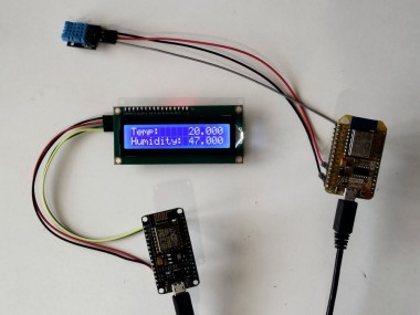
Congratulations! You have completed the project.
Picture 1 shows the connected and powered up project. As you can see on the picture the Display will show the temperature and the Humidity.
On Picture 2 you can see the complete Visuino diagram for the Temperature and Humidity measuring module.
On Picture 3 you can see the complete Visuino diagram for the I2C LCD Display module.
Also attached are the Visuino projects, that I created for this Tutorial. You can download and open them in Visuino: https://www.visuino.com
Credits
Related products


Leave your feedback...