

Reinforcement Learning Based Illumination Controller

Made by MaverickBits / Artificial intelligence / Environmental Sensing / Home Automation / Sensors / IoT
About the project
This project envisages a reinforcement learning based automatic home illumination system. The system shall learn and adapt to the preferred illumination settings from immediate ambient conditions. The system shall also perpetually, keep learning and optimizing itself based upon the accuracy of its control predictions.
Project info
Items used in this project
Hardware components

Software apps and online services
Story
NXP [1] and Electromaker [2] have organized the NXP – Hackathon 2021 [3] event. To compete in this event, it was required to develop a project based upon MIMXRT1020 EVK [4] development platform. In this context, this project envisages a Reinforcement Learning [5] based illumination controller.
The idea of the project is to develop a reinforcement learning based adaptive illumination controller which adjusts the overall illumination to balance the current simulated environmental illumination.
As we discuss in further in section 4, to achieve this goal we use MIMXRT1020 EVK [4], along with 1 x Adafruit TSL2591 High Dynamic Range Digital Light Sensor [6] and 2 x Adafruit LED Backpacks with HT16K33 [7].
Most automatic illumination control algorithms operate as a closed loop system, where the controller senses the environment and adjusts the lighting conditions in discreet steps. These algorithms often lead to inaccurate illumination that are either too slow or too quick to respond to environmental changes and have limited adaptability.
To address this issue, this project envisages a reinforcement learning [5] based automatic home illumination system, where the system shall learn the preferred illumination settings from immediate time/date and ambient conditions. The system shall also perpetually, keep learning and optimizing itself based upon the accuracy of its control predictions.
There are various advantages to this system, the reinforcement learning algorithm can gradually lead to a system which can be highly personalized to users and the ambient lightning conditions. In case, of any drastic changes to the environment, the system shall be able to adapt as well. Also, since we shall be using reinforcement learning, the system will not require large datasets/labels as required for supervised learning. The compute resources required shall also be a fraction of any supervised learning algorithm - ideal for IoT systems.
Further, the core idea of the project can be generalized to design a reinforcement learning based IoT development platform, which can be applied to any end user application. This quick and low-cost rapid prototype can also be useful in highlighting some of the key issues and bottlenecks of such as system, thus aiding in making more informed design choices for a full-fledged system. The outcome of such a system could simply be a reinforcement learning middleware library shipped as a part of the MCUXpresso SDK [8].
The aim of this project is to serve as a proof of concept for a Machine Learning based Illumination controller developed for MIMXRT1020 EVK [4]. The project does not aim to be a product; however, it can be used as a test and demonstration platform upon which further development can be carried out to productize the concept.
To achieve the above objectives, the project envisages a simulated environment where the variations of a typical “sunny” day profile is simulated, and the overall illumination is held constant adaptively irrespective of the time of the day. It is understood that the simulated environment is different from real world scenario. However, this approach provides a quick evaluation of the reinforcement algorithm and a setup where furthermore realistic development can be carried out.
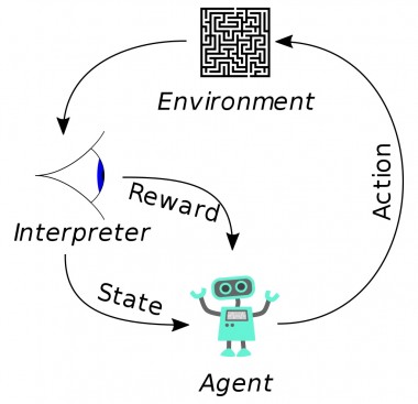
Reinforcement learning (RL) is an area of machine learning concerned with how intelligent agents ought to take actions in an environment in order to maximize the notion of cumulative reward. It is one of three basic machine learning paradigms, alongside supervised learning and unsupervised learning [9].
This notion of learning is inspired from natural biological learning systems. For example, biological brains are hardwired to interpret signals such as pain and hunger as negative reinforcements and interpret pleasure and food intake as positive reinforcements. In some circumstances, animals can learn to engage in behaviors that optimize these rewards [9].

Figure 1: Reinforcement Learning [Wiki]
The Figure 1, shows a basic high-level overview of the algorithm. The system consists of an Agent which takes an action to switch to another state based upon the highest expected reward. After switching to the new state, the actual reward is observed and accumulated. Over a period, the agent can devise a policy of decision making which maximizes the expected cumulative reward.
In mathematical terms, reinforcement learning can be implemented by using Markov decision process (MDP) [10]. We consider an Agent in State and a set of actions of the agent.
In its simplest form, an Agent interacts with its environment in discrete time steps . In each of these steps the agent is said to be in state with reward . Then agent selects an action from the set of available actions to switch to another state and observes the reward associated with the transition. The goal is to learn a policy (eq. 2) to maximize the expected cumulated reward .
In this project, the MIMXRT1020-EVK [4] is used as the core processing platform. This is an ARM Cortex-M7 core, 500MHz MCU developed by NXP [1]. It targets the edge computing platforms providing high performance at low cost. The SoC consists of various integrated peripherals controllers such as SDMMC, Wi-Fi, Ethernet, Bluetooth, QSPI, I2C, SPI, CAN, UART and many more making it a very versatile SoC which can meet the requirements of a vast range of applications. We also have a mature software ecosystem and tools supported by both open source and closed source community. For example, the MCUXpresso IDE [11] provides all the necessary software stacks for rapid prototyping and development. It provides support for both bare-metal or RTOS based development and the necessary startup initialization code for the SoC, device controllers and on board EVK peripherals.
Figure 3, shows a high-level hardware architecture of the system and Figure 2 shows the wiring diagram.
All datasheets and board files are available here: https://github.com/subhasish-ghosh/MIMXRT1021_RLIC_Main/tree/main/docs/data/datasheets
Below are descriptions of the peripherals integrated for the project.
The TSL2591-EVK [6] module from Adafruit is a High Dynamic Range Digital Light Sensor. In this project, this module is utilized as the main environmental sensor for the reinforcement learning algorithm. The TSL2591-EVK has an I2C interface to the host processor which makes it very easy to integrate quickly into any system. The module could be powered by both 5V and 3V3. For this project, a 3V3 source and ground was provided from MIMXRT1020-EVK. Connector J19, Pin-8 and Pin-7 were used for the purpose. Further, LPI2C4 was utilized for I2C bus interface to the MCU. The device address was setup as 0x29 and operated at 100KHz bus frequency. On the EVK, Connector J19 Pin-9 and Pin-10, were used to provide the I2C SDA and SCL interface. Further details about this device can be found here: https://learn.adafruit.com/adafruit-tsl2591.
The HT16K33-EVK [7] module from Adafruit is utilized as light sources for the project. There are two modules used for the project, one for simulating day light transitions and the other as an adaptive light source to compensate for daylight changes. The HT16K33-EVK has an I2C interface to the host processor which makes it very easy to integrate quickly into any system. The module could be powered by both 5V and 3V3. For this project, a 5V source and ground was provided from MIMXRT1020-EVK J20, Pin-5 and Pin-6, respectively. Further, LPI2C1 was utilized for I2C bus interface to the MCU. The device addresses were setup as 0x70 and 0x72, operated at 100KHz bus frequency. On the EVK Connector J18 Pin-5 and Pin-6, were used to provide the I2C SDA and SCL interface. The address selection was performed via resistor soldering. Further details about this device can be found here: https://learn.adafruit.com/adafruit-led-backpack.

Figure 2: Wiring Diagram
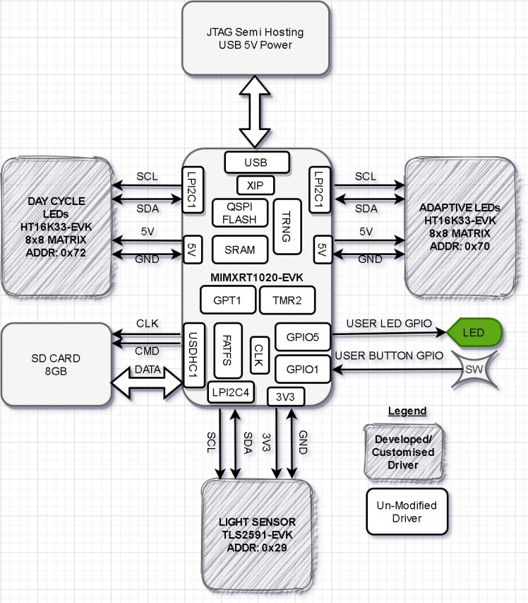 Figure 3: System Block Diagram
In this section, we discuss about the software modules implemented for the project. The entire source code and associated doxygen documentation can be found here:
https://github.com/subhasish-ghosh/MIMXRT1021_RLIC_Main
The sources are implemented as a single Bare Metal C++ project. There are multiple classes and their interdependencies are graphically shown here:
https://subhasish-ghosh.github.io/MIMXRT1021_RLIC_Main
The memory footprint of the project is shown in Figure 4.
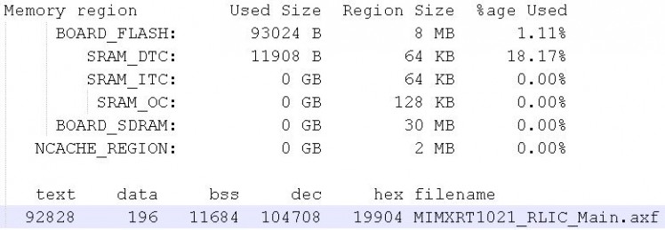
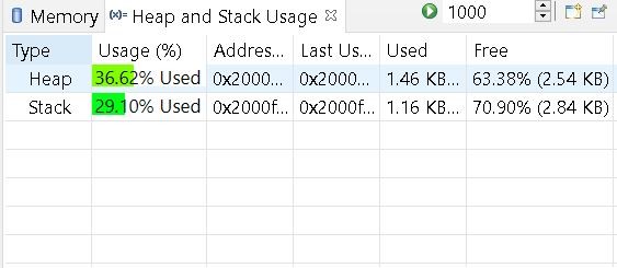
Figure 4: Memory Footprint
The main control flow is discussed in section 7.2. Then individual modules are further discussed. The control flow did not require to be implemented as a state machine because it was not necessary to switch between states.
The Figure 5 shows the control flow of the main loop of the system.
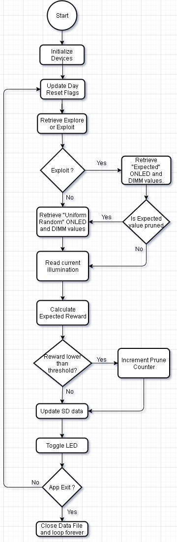
Figure 5: Main Loop
The initialization phase of the MPU is covered in two phases. In the first phase, four functions are implemented to initialize the base system:
BOARD_ConfigMPU(),
BOARD_InitBootPins(),
BOARD_InitBootClocks()
BOARD_InitBootPeripherals()
The first three functions, initializes the memory and cache attributes of the MPU, followed by Pin Mux and clock tree. The final function InitBootPeripherals(), initializes the various controller drivers and associated clocks. These include the LPI2C, GPIO, TMR, GPT and TRNG.
In the second phase, the LED Matrix (HT16K33), the Light Sensor (TSL2591) and the SD Card FATFS storage is initialized. Finally, the TMR interrupts are enabled.
After all the devices have been initialized, we enter the main loop of the algorithm. In this stage, first we check the state of the dayReset flag. This flag is used for the day light simulation (see 7.3), as shown in Figure 7.
Next, the Reinforcement Learning Algorithm is started. The function runExploreExploit() is executed to retrieve a decision on Exploration vs Exploitation (see 7.5). Based upon the output, the function getQBrightness(), is called (see 7.6). Then this brightness is set using setLedBrightness() in the Adaptive LED target (I2C addr: 0x70) and the current illumination is read back using getLuminosity().
Finally, in the function updateQTable(), the expected reward is calculated. If the current reward is lower than a threshold, then that set of ONLED and DIMM values are pruned. This is done to speed up learning by reducing the search state space. Then as a system “Heartbeat”, the USER LED is toggled. The delay for the LED toggle is implemented using Sys Tick timers. There is also a provision added to allow the application to exit gracefully. This is done by reading the SW4 switch state. In case, the SW4 is activated, the application saves and closes the data file and enters an infinite loop. The USER LED toggle rate at this point is also changed to indicate that the process was successful.
The flow diagram for day light simulation is shown in Figure 6 and the corresponding illumination generated by the LED board is shown in Figure 7.
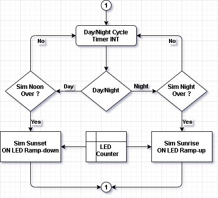
Figure 6: Day Light Simulation Flow
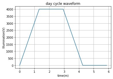
Figure 7: Day Light Waveform
The core idea behind the daylight simulation is to evaluate the reinforcement learning algorithm by speeding up the learning process. In this algorithm, the number of ONLED and LED DIMM (see 7.6) values are gradually increased, simulating a sunrise event. The highest illumination achievable is around 4000 units. This illumination is then held constant for a period, simulating an afternoon event. In the next stage, the reverse operation is carried out. First, the ONLED and DIMM values are gradually decreased and then held for some time at the lowest values.
The algorithm is implemented using TMR2 and LPI2C1. The TMR2 is configured to generate interrupts every 1 second. Upon receiving this interrupt, the day cycle algorithm is triggered. Then depending upon the current state of the simulation, the number of ONLED and LED DIMM (see 7.6) values are set.
The overall day cycle time is approximately 6 minutes. This 6 minute is discretized into approximately 440 iterations. That means that the core loop algorithm as shown in Figure 5, is executed 440 time for a day cycle. This sense of elapsed execution time is implemented using Sys Tick timer.
The reward for the system is gathered using the function getReward(). The reward structure is shown in Figure 8. The ideal illumination is set to 4500 units. As the overall illumination drifts away from 4500, the reward decreases. This finally feeds back into the reinforcement learning algorithm.
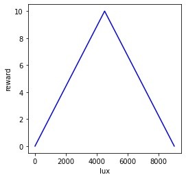
Figure 8: Reward plot
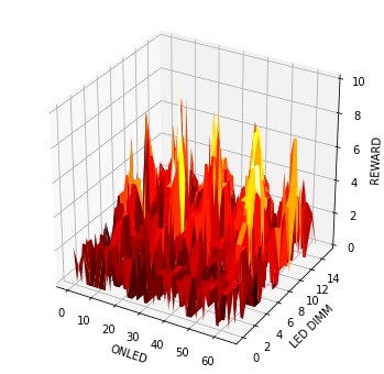
Figure 9: Initial Learning
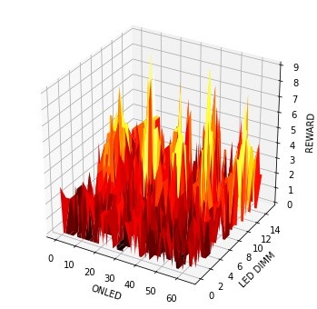
Figure 10: Learning Progress - 1

Figure 11: Learning Progress - 2
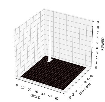
Figure 12: Learning Progress - Final
Figure 9, Figure 10, Figure 11, Figure 12 shows the learning progress at approximately the 100th second over four days of training. These images show the rewards generated for specific combinations of ONLED and DIMM combinations. Higher peaks indicate higher reward achieved. Over a period of four days, we can see that the system gradually adapts to the most optimal ONLED and DIMM values.
7.5 Exploration and Exploitation
One of the core concepts reinforcement learning is the notion of exploration vs exploitation. The idea is very simple, while taking a state-action decision, a choice is made to either utilize the most expected reward or choose something randomly. The idea is to avoid getting stuck in any local optima. Consider Figure 9, as we can see that there are multiple locations where high reward can be achieved, however, some states are still higher than other. By using only exploitation, the system could be stuck at a reward level of 8, for example, this is a local optimum. However, by utilizing certain percentage of state-action pairs, where the decision is made randomly, it is possible to search for a global optimum, which is the highest possible reward possible for a specific state. To understand more about this concept, refer the Multi Arm Bandit Problem [12]. Note that for this project, the exploration is disabled to speed up learning. Hence, this project is only run-in exploitation mode.
7.6 Retrieving LED and DIMM
As we discussed in section 6.3, HT16K33 [7] is used as an Illumination source for the project. This device implements a RAM structure to turn on or off the LEDs. The device also has a dimming setting, which can be used adjust the brightness. We refer to ‘ONLED’ to indicate the number of on LEDs and ‘DIMM’ as the dimming settings. The ONLED values range from 0 to 64 and the DIMM setting range from 0 to 15. We refer to the tuple [ONLED, DIMM] as a ‘State’ throughout this document.
To retrieve the ONLED and DIMM settings, the function getQBrightness() is called from within the QLearning class. This function optionally reads the qtable from the SDCard, then depending on the exploration/exploitation mode, retrieves ONLED and DIMM values for the highest expected reward. The function also checks if certain states are pruned, in that case it ignores such states.
As discussed in section 6.2, TSL2591 [6] is used as the light sensor for the project. The device implements a high-resolution light sensor that can be configured for different gain/timing ranges to detect light ranges from up to 188uLux up to 88,000 Lux on the fly.
The illumination is retrieved using the using the function getLuminosity() from within the Adafruit_TSL2591 class. There are some configuration options available, these are the gain settings and integration time settings. Both these settings were configured from within the configureSensor() function during the initialization phase of the application.
The RLIC.dat file is used to store the expected rewards and prune table of the reinforcement learning algorithm. During the initialization phase, the application checks for the RLIC.dat file presence in the SD Card file system (FATFS). If the file is not present, then it is created. If present, the reward stored in this file is used and the learning continues. The size of the file is 1000 * 4096, i.e., there is 1000 entries of 4KB each. These 1000 entries are further partitioned into two parts. The Index-0 to store the expected reward and Index-1 to store the prune table.
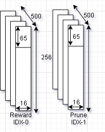
Figure 13: RLIC.dat file
In the Qtable, these indexes are referenced as ‘QTABLE_IDX’ and ‘QTABLE_PRUNED_IDX’ in the source code. Each of the 500 entries are arranged like a matrix of ONLED x DIMM, i.e., 65 x 16. This uses 1040B from the 4KB space, the rest of the space is empty. The structure of the RLIC.dat file is shown in Figure 13. The 500 table entries each is associated with the number of iterations as discussed in section 7.3. If the day cycle simulation is altered such that there can be more than 500 iterations possible, then the dimension of this file is required to be changed.
The learned weight for the project is available here:
https://github.com/subhasish-ghosh/MIMXRT1021_RLIC_Main/tree/main/docs/data/weights
The initial learning process for a reinforcement learning algorithm can be very slow. This is because the algorithm needs to interact with the real-world environment and learn all possible stimulus. Without this initial step of “basic training”, deployed products can disrupt the end user as the system learns from scratch.
This initial training needs to be executed only once, then the “experience” can be shared across multiple units of the product. Individual systems can then continue adapting without major disruption. However, due to this initial slow training, deployment of reinforcement learning products can be time consuming.
To circumvent this issue, there is a need for robust simulation environment, where physical processes can be accurately modelled and executed at much higher rates than real world scenarios. One example of such a simulation environment is the OpenAI Gym [13] environment. However, this is completely software simulation environment and thus there remains a need to train on real physical systems to address the unpredictability of real-world scenarios.
In this project, we implement a Day Light Simulation environment. The idea is to simulate a typical day time scenario, this is further discussed in section 7.3.
To create a confined environment, the setup was concealed within a light resistant enclosure as shown in Figure 14. A camera was placed inside to view the training process without disrupting the setup. The video for the entire execution flow is available here:
https://github.com/subhasish-ghosh/MIMXRT1021_RLIC_Main/blob/main/docs/video/rlic.mp4
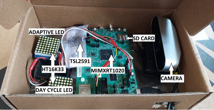
Figure 14: Simulation Setup
Reproducing the project is simple. Follow the steps below:
· Construct the prototype as shown in Figure 2: Wiring Diagram.
· Construct a confined environment as shown in Figure 14.
· Download the source code from: https://github.com/subhasish-ghosh/MIMXRT1021_RLIC_Main
· Import the project file MIMXRT1021_RLIC_Main.mex into MCUXpresso IDE.
· Compile and Flash the Code into the MIMXRT1020 EVK.
· Insert the SD Card.
· Optionally copy the learned weights into the SD Card as follows:
o Format SD Card with FATFS.
o Copy the weights into the card:
§ Available here: https://github.com/subhasish-ghosh/MIMXRT1021_RLIC_Main/tree/main/docs/data/weights
§ Copy into: SDCARD:/DIR_1/RLIC.dat
· Power on the target and leave it for 4 days.
· The system will automatically learn to adapt to the changing day cycle.
The following are the deliverables for the project:
1 Source Code https://github.com/subhasish-ghosh/MIMXRT1021_RLIC_Main
2 Datasheets https://github.com/subhasish-ghosh/MIMXRT1021_RLIC_Main/tree/main/docs/data/datasheets
3 Weights https://github.com/subhasish-ghosh/MIMXRT1021_RLIC_Main/tree/main/docs/data/weights
4 Docs https://subhasish-ghosh.github.io/MIMXRT1021_RLIC_Main
5 Video https://github.com/subhasish-ghosh/MIMXRT1021_RLIC_Main/tree/main/docs/video
6 RLIC.pdf This document
· Integration time of TSL2591 is too slow (up to 400ms). Due to which the system can execute at most twice within a second. This is slowing down learning.
· HT15K33 LED response time is too slow, due to which TSL2591 is requiring higher integration time.
· Due to the above two issues, sometimes stable states are being pruned.
· Exploration is disabled to speed up learning.
· Pruning threshold is reduced to ‘8’ to speed up learning.
· Un-pruning of prune table is disabled because exploration is disabled.
Below we discuss some of the pros and cons of the project:
Pros:
· The system can learn and maintain adaptive illumination in 80% to 85% of the states.
· This rapid prototype highlighted many issues expected in productizing such a project.
· Low cost and easy to setup.
· Uses only openly available resources. No closed source used.
· No RTOS required.
· There are no known software bugs. The system behavior is as expected.
· Low memory footprint.
Cons:
· Although the system can learn up to 85%of the states, there is still room for improvement.
· The search state space is too wide with up to 65x16 actions possible in each state. Possibly some more thought is required to better formulate the reinforcement learning problem.
· Only one day profile is simulated. More robust simulation environment is required.
· The day cycle simulation algorithm needs to be expanded. Currently only one profile is simulated. It should be possible to simulate multiple such profiles on independent hardware.
· Full software simulation is required with detailed environmental modelling.
Light sensor with faster integration time is required. Further, LEDs are required with better response times.
[1]NXP, “NXP,” [Online]. Available: https://www.nxp.com/. [Accessed 21 June 2021].
[2]Electromaker, “Electromaker,” [Online]. Available: https://www.electromaker.io/. [Accessed 21 June 2021].
[3]Electromaker, “NXP Hackathon 2021,” [Online]. Available: https://www.electromaker.io/contest/nxp-hackathon-2021. [Accessed 21 June 2021].
[4]NXP, “MIMXRT1020-EVK: i.MX RT1020 Evaluation Kit,” [Online]. Available: https://www.nxp.com/design/development-boards/i-mx-evaluation-and-development-boards/i-mx-rt1020-evaluation-kit:MIMXRT1020-EVK. [Accessed 21 June 2021].
[5]R. S. S. a. A. G. Barto, Reinforcement Learning: An Introduction, Cambridge, Massachusetts, London, England: The MIT Press, 2015.
[6]Adafruit, “Adafruit TSL2591 High Dynamic Range Digital Light Sensor,” [Online]. Available: https://learn.adafruit.com/adafruit-tsl2591. [Accessed 21 June 2021].
[7]Adafruit, “Adafruit LED Backpacks,” [Online]. Available: https://learn.adafruit.com/adafruit-led-backpack. [Accessed 21 June 2021].
[8]NXP, “MCUXpresso Software Development Kit (SDK),” [Online]. Available: https://www.nxp.com/design/software/development-software/mcuxpresso-software-and-tools-/mcuxpresso-software-development-kit-sdk:MCUXpresso-SDK. [Accessed 21 June 2021].
[9]Wikipedia, “Reinforcement learning,” [Online]. Available: https://en.wikipedia.org/wiki/Reinforcement_learning. [Accessed 21 June 2021].
[10]Wikipedia, “Markov decision process,” [Online]. Available: https://en.wikipedia.org/wiki/Markov_decision_process. [Accessed 21 June 2021].
[11]NXP, “MCUXpresso Integrated Development Environment (IDE),” [Online]. Available: https://www.nxp.com/design/software/development-software/mcuxpresso-software-and-tools-/mcuxpresso-integrated-development-environment-ide:MCUXpresso-IDE. [Accessed 21 June 2021].
[12]Wikipedia, “Multi-armed bandit,” [Online]. Available: https://en.wikipedia.org/wiki/Multi-armed_bandit. [Accessed 21 June 2021].
[13]OpenAI, “OpenAI Gym,” [Online]. Available: https://gym.openai.com/. [Accessed 21 June 2021].
Schematics, diagrams and documents
Code
Credits
Related products


Leave your feedback...