
Power Your Coffee Maker With Netduino
Made by Wilderness Labs / 3D Printing / Communication / Food & Drinks / Home Automation / Productivity
About the project
Control your coffee maker remotely! Create a connected coffee maker using household electricity with .NET, Netduino, and Xamarin.
Project info
Difficulty: Moderate
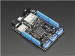
Platforms: Microsoft, Xamarin, Netduino
Estimated time: 2 hours
License: Apache License 2.0 (Apache-2.0)
Items used in this project
Hardware components


View all
Hand tools and fabrication machines
View all
Story
Part 1: Connected Power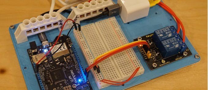
Did you know that you can power Netduino from a cheap USB charger? We were working on some Netduino-controlled appliance hacks, and I thought it would be helpful to share a quick hack to power Netduino from household electricity using a cheap USB charger that can be integrated directly into an appliance circuit.
It’s super easy, it only requires a USB charger, some appliance/lamp cord, a couple pieces of shrink wrap tubing, and 1/4″ female disconnects to make our adapter connectable to a typical household wiring circuit:

Of course, if you don’t need to tie the power into a household electrical circuit, you can just plug the adapter straight into the wall and power the Netduino from a micro USB cable.
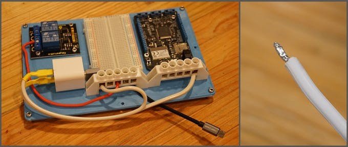
If you’re building an appliance control circuit, however, you can use this hack to tie the Netduino power adapter directly into the circuit, so you only have one cord that needs to be plugged into the wall. For instance, we used some double sided tape to attach our USB adapter to our appliance control board, and all of our power, both for the appliance control circuit, and the Netduino is taken care of:
Step 1 - Separate and Strip the Wires
First, cut the lamp cord and then start separating it down the center with a razor blade: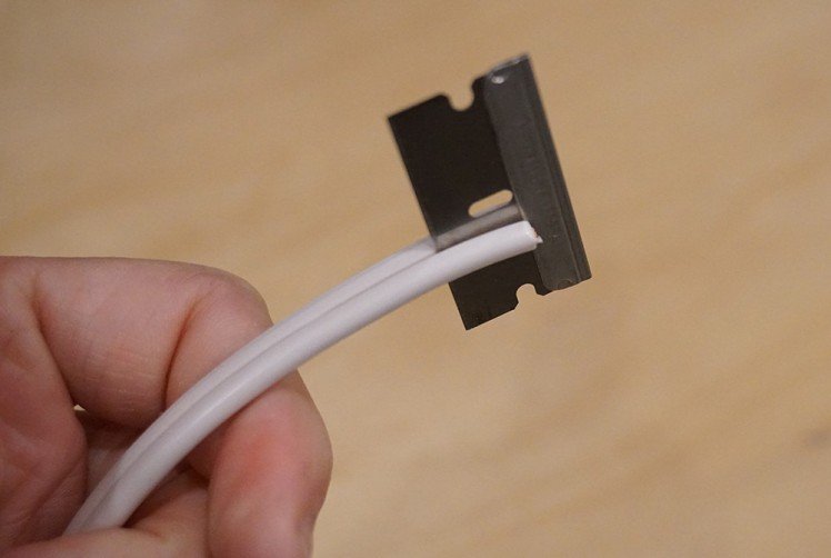
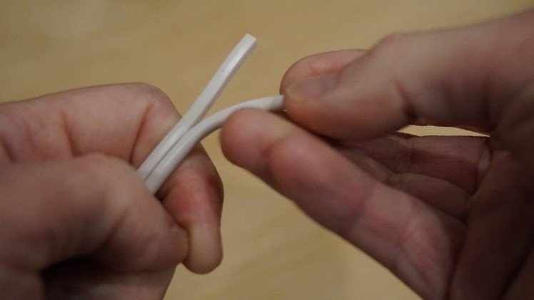
Next, use your fingers to pull the cord apart, you’ll need a probably about 5cm or 2″ free:
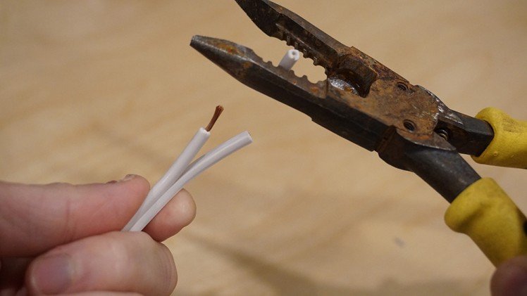
 Once the cord is separated a bit, use a wire-stripper to pull off about a centimeter or so of the insulation:
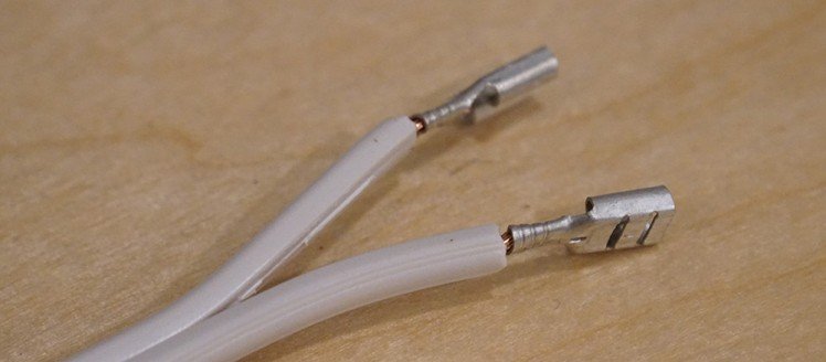
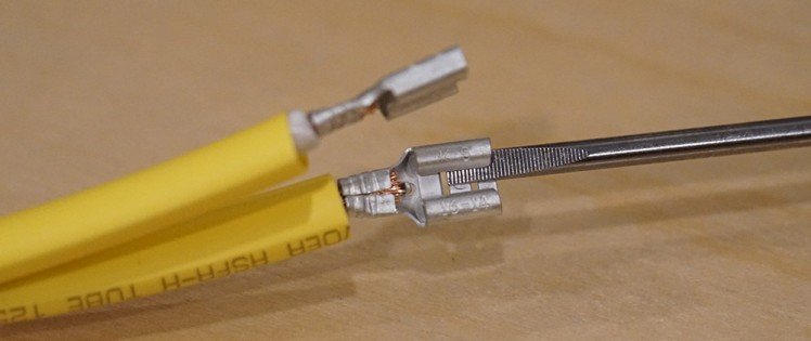
Step 2 - Attach Female Disconnects
Once the wire is stripped, we can add the female disconnects. Slide them over the bare wire and then use a crimper to crush the disconnect attachment point onto the wire. For added protection, you can add a little solder, but it’s usually not necessary:
 We’re just about ready to attach the disconnects to the adapter, but first, we need to slide some short sections of heat shrink tubing over the wire. We’ll heat this later, for now, just slide it over the end:

Step 3 - Connect to USB Charger
Once the tubing is on, attach the disconnects to the plug prongs:
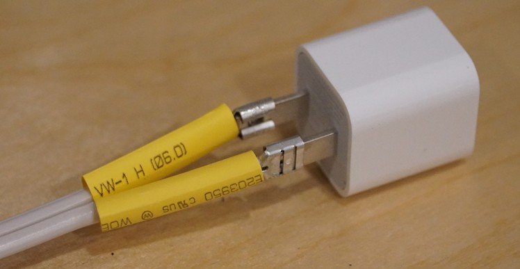
They'll probably be pretty tight, so you may want to loosen them a little with a small screwdriver to fit them over:
Don't loosen them too much, they should be pretty tight on the plug prongs so they don't disconnect.
Step 4 - Heat the Heat Shrink Tubing
Now that the disconnects are on, we can finalize our work by using a heat gun (or hair dryer) to shrink the tubing and provide insulation:
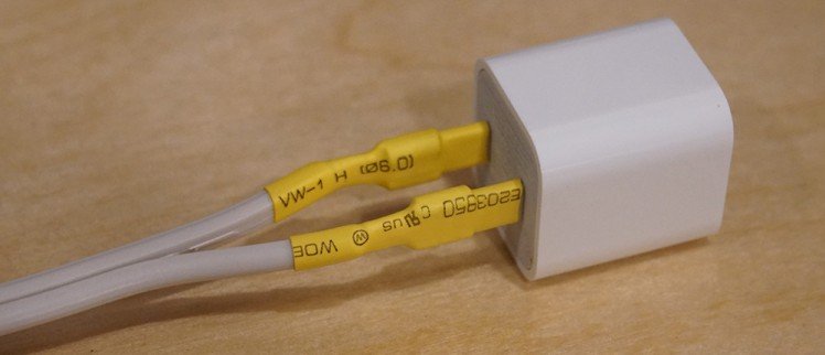
That's it! Now we have a power adapter for a Netduino that we can hook directly into a household electrical circuit!
Part 2: Control
In part 1, we created a power adapter from a USB charger that can be used to power a Netduino when it isn’t plugged into the computer. In this part, we’re going to create what is, in essence, a smart power outlet; a household electrical circuit that can be turned on or off by a Netduino. In this example, we’re going to use a simple coffee pot that has an on/off switch, but any simple appliance can be controlled this way. Later on, we’ll add more complexities such as controlling this outlet via a mobile app talking to a web API on the Netduino.

WARNING:
Before going any further, it’s important to note that this project is meant to control household electricity. That’s 120V in North America, and 240V in many other places. Household electricity can kill you. It probably won’t; I’ve done enough electrical household wiring to be shocked more times than I care to admit, but in certain situations, it certainly can be deadly. When this project is assembled and plugged in, the terminal blocks and relay terminals will be live and can shock you if not handled with care. All the live conducts are protected by plastic, but if you stick metal, such as a screwdriver in them, you can get shocked. Keep this prototype away from children who might stick small fingers into the terminals or get a hold of the live wires some other way. Additionally, when not in use, it should be unplugged from the electrical outlet.
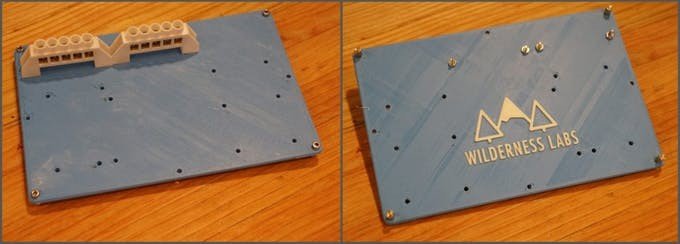
Step 1 - Print Baseboard and Clean Holes
First, we need a baseboard to put all our prototype boards on. Download and print the Appliance Control Board from our 3D print designs Github repo. If you don't have a 3D printer, you can also make one of these from a 3/16" - 1/4" thick sheet of plywood. The 3D print repo contains the original .DWG file with dimensions. AutoDesk publishes viewers to view the file to get dimensions.
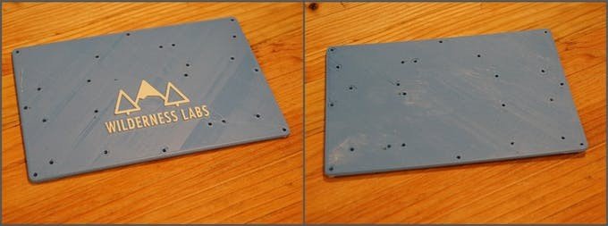 3D-printed Appliance Control Board (see our 3D print designs Github repo)
After it's printed, I find the holes usually need to be reamed out with a 3.2mm (1/8") drill bit, otherwise the bolts don't fit through.
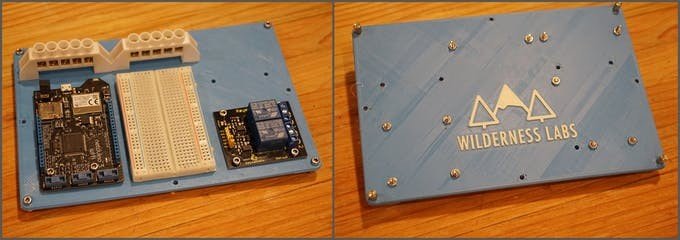
Step 2 - Attach Screw Terminal Blocks and Boards
Once the holes have been cleaned, it's time to start assembling the baseboard. First, using (4) 12mm M3 socket screws and (4) hex spacers, install "feet" on the corners of the board. This gives clearance on the board by raising it off the work surface. Then attach the terminal blocks as shown:
Once the boards and terminal blocks are on, put some mounting tape on the power adapter, and remove backing. Make sure to put it on the correct side:
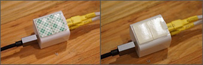
Then attach the power adapter to baseboard. Make sure the USB cable fits as follows:
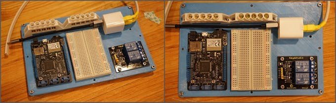
Step 3 - Wire the Power Adapter In
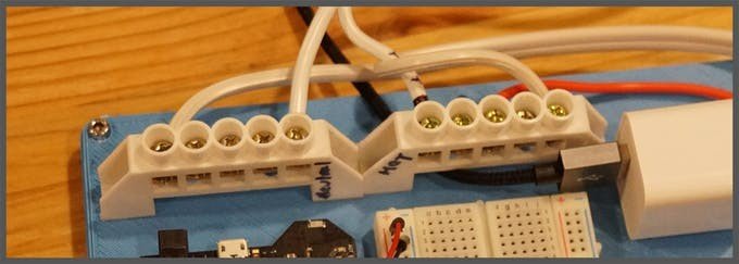
Next, we want to wire the power adapter into our screw terminals. These screw terminals will be used to distribute our household electrical power (120V/240V). However, I've found that these screw terminals are meant to handle a little larger wire, so I recommend stripping and then soldering the end of the wire so it provides a more solid contact point:
It doesn't matter which wire goes to which screw terminal, as long as the wires are divided between the blocks. You can ignore the red wire above for now.
Step 4 - Add the DC Circuit Control Wires
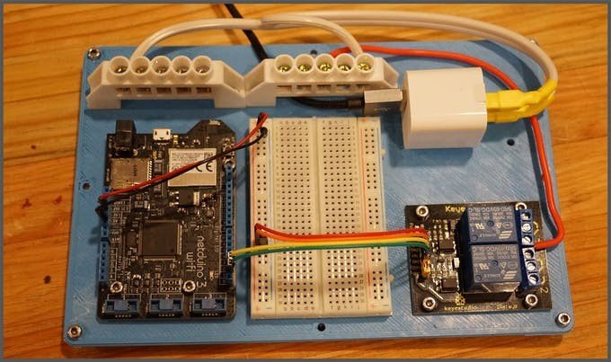
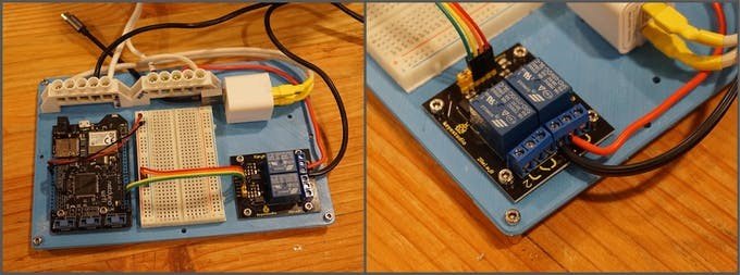
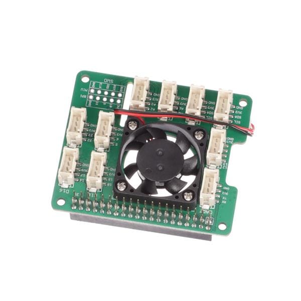
Now we can add all the DC control circuit wires. The wiring for this is very simple; the relay requires power and ground and then a digital IO wire for each relay.
In this example, the breadboard is not actually needed, but by having it, we can add more complex circuits later. In the photo below, you can see that I’ve used male to male jumpers to wire the power rail (3.3V and GND) of the Netduino to the left power rail on the breadboard. This gives us a common power rail to add more circuits. I’ve also tied that into the relay with the red and orange wires. Note that it really doesn’t matter what colors of wire you use.
Finally, I’ve wired the Netduino digital IO pins 2 and 3 to the IN2 and IN1, respectively, on the relay board. In our case, we’ll actually only use one of the two relay channels available. Note that for the relay board, you’ll need male to female jumpers, since the relay exposes male pins.
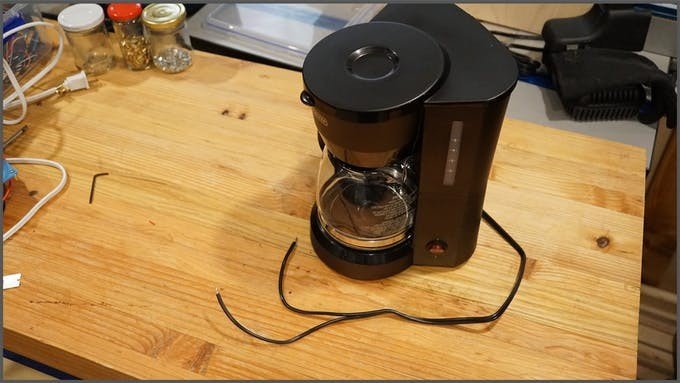
Step 5 - Prepare the Appliance Cord
Next, we need to cut the plug off the coffee maker, strip the ends, and optionally, add a little solder:
Step 6 - Add our Household Electrical Power
Next, cut and strip the end of the extension cord. It's a good idea to make the Hot and Neutral sides, through in practice, with AC appliances, it almost never matters. For North American plugs the hot side is the smaller prong, and the Neutral side is the larger prong. For other plugs, refer to this Wikipedia article on AC power plugs and sockets.
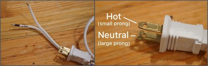
Then, connect the household power extension cord to the terminal blocks. Each terminal block should get one of the wires. I've labeled the neutral and hot, but again, it's unnecessary 99.9% of the time:
Step 7 - Wire the Coffee Pot into the Circuit
The last thing we need to do to finish our circuit is to wire the coffee pot into the relay. A relay is an electromechanical switch that uses an electromagnet to physical move the switch. Relays are often used in setups like this because you can control larger and/or different types of current with a small DC current. In this case, we’re using 3.3V of DC to control a switch that controls 120V or 240V AC. For a more detailed discussion of how they work, see our relay guide.
The relay board that we’re using is a two channel relay board, meaning that it has two relays, to control two separate circuits. We’re only going to need one relay for now. For each relay, there are three screw terminals that correspond to the normally closed wire, the power wire, and the normally open wire. Normally closed and normally open refer to whether or not that side of the switch is connected to the center power wire when the relay is not powered. In this case, we need to connect the center terminal to the hot side of our household electrical terminal block, and then the normally open terminal to one of side of the coffee maker cord. The other wire of the coffee maker should then go to the neutral main screw terminal block.
The idea here is that when the relay is powered, it switches to connect the normally closed side to the power. This then creates a closed circuit through the coffee maker of neutral household main > coffee maker > normally closed terminal > hot household main:
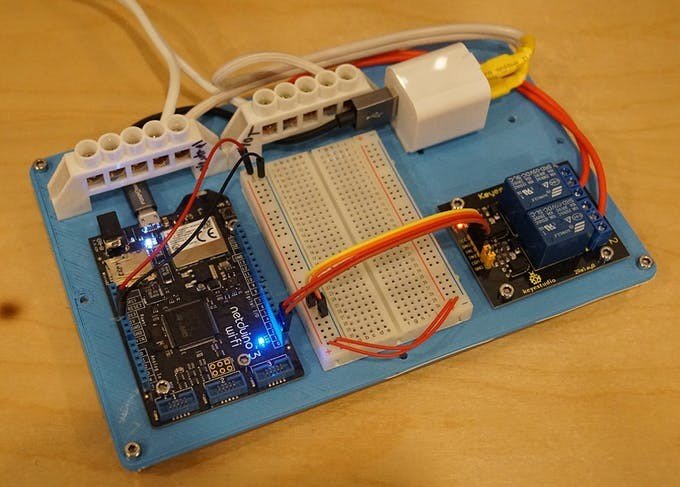
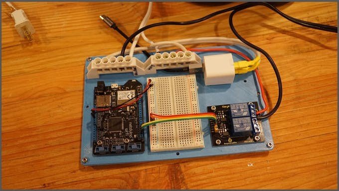
When all the wiring is done, it should look something like the following:
Step 8 - Double-check the Wiring
Now that everything is wired up, it’s time to test our AC circuit to make sure that we don’t cause a short-circuit. While it’s unplugged from the wall, double-check that the extension cord wires are firmly in place with good connection and that they’re on different terminal blocks. Putting them on the same terminal block will cause a short-circuit and immediately cause the circuit breaker (or fuse) that your wall outlet is connected to, to trip. It may also cause sparks. we don’t want that.
Next, make sure that the coffee pot wires are also on different terminal blocks; one should be on neutral, and the other should connect to the hot terminal block, by way of the relay.
Finally, make sure that the USB adapter wires also go to different terminal blocks; one to the neutral and one to the hot.
After you’ve double-checked all those connections, plug the USB cable into the Netduino, and plug the extension cord into the wall outlet. If all is well, the Netduino and relay board should be powered. Unplug the extension cord from the wall, an unplug the USB cable from the Netduino. Next, we’re going to program the Netduino.
Step 9 - Test Control from Code
Plug the Netduino into your computer, launch Visual Studio, create a new .NET MicroFramework application called Connected_Coffee_SimpleControl, and add references to the following dlls:
- Microsoft.SPOT.Hardware
- System
- SecretLabs.NETMF.Hardware.Netduino
Next, paste the following code in your program.cs file:
- using Microsoft.SPOT.Hardware;
- using SecretLabs.NETMF.Hardware.Netduino;
- using System.Threading;
- namespace Connected_Coffee_SimpleControl
- {
- public class Program
- {
- public static void Main()
- {
- // create an output port (a port that can be written to) and
- // connect it to Digital Pin 2
- OutputPort relay = new OutputPort(Pins.GPIO_PIN_D2, false);
- // run forever
- while (true)
- {
- relay.Write(true); // turn on the relay
- Thread.Sleep(5000); // Leave on for 5 seconds
- relay.Write(false); // turn off the relay
- Thread.Sleep(5000); // leave off for 5 seconds
- }
- }
- }
- }
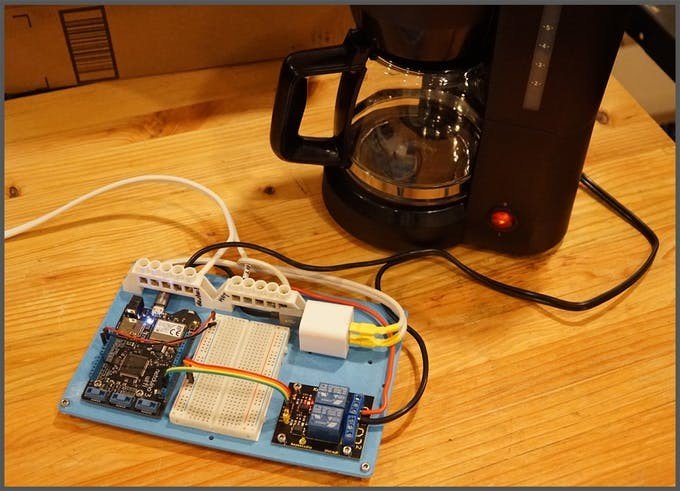
This code will simply turn the coffee pot on for 5 seconds, then turn it off, and repeat. To test it, make sure the switch on the coffee pot is on, then plug the extension cord for the appliance control board into the wall and deploy the app. You should hear an audible “click” as the relay actuates, and the coffee maker light should come on. It’ll stay on for five seconds, and then turn off.
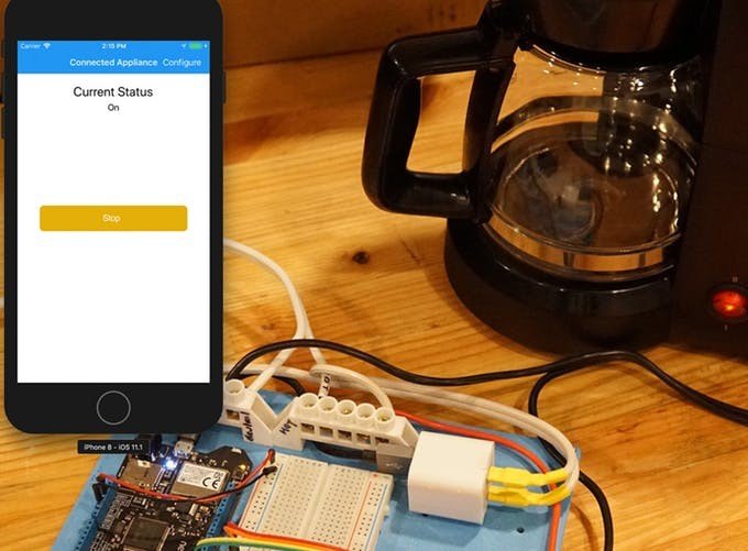
And once the program is deployed, it will run as long as the Netduino is plugged into power. So after deploying the program, you can plug the Netduino back into the USB power adapter, plug the extension cord back into the wall, and see it run:
Step 10 - Pat yourself on the back!
Congratulations!! You've now built a basic control circuit for a connected appliance! In the part 3 of this series, we're going to add the "connected" part of this project by adding a web API that runs on the Netduino so that we can control this remotely, from a web browser, or a mobile app!
Part 3: Introducing Maple Server
In part 2, we built the core of the connected coffee maker by creating what was essentially a smart power outlet that we could control with a Netduino. After assembling the hardware, we deployed an application that controlled our relay to to turn on household power to the coffee maker, effectively adding simple control.
In this entry part, we’re going to take this one step further and add a web API to the Netduino application so that we can control it remotely.
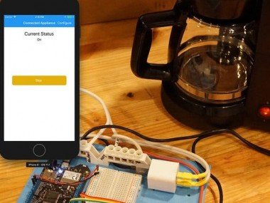
Once we have the web API in place, we will have an endpoint that can be taken advantage of from a variety of use cases. In fact, in the next part, we’ll build a Xamarin.Forms mobile application that uses that API to control the connected coffee pot from a mobile device:
The sample code for the entire connected coffee maker project can be found in the Netduino_Samples/Connected_CoffeeMaker repo. The code that runs on the Netduino is in the ApplianceHost app folder. That’s the code we’ll be examining here.
Introducing Maple Web Server
In order to expose the web API to allow remote control of our coffee maker, we need a web server to host it. So we’re introducing a purpose-built web server for Netduino; Maple Server.

Maple is an open source, ultra-lightweight, JSON enabled, RESTful web server built specifically for Netduino devices with network capability. It’s also published as a nuget package, so it’s incredibly easy to add to your projects. We purpose-built it for Netduino; it’s incredibly simple, fast, and super easy to use. It should run without issue on the N3 Ethernet, N3 Wifi, and N2+ models.
Request Handlers
Maple web API endpoints are defined by creating custom classes that inherit from RequestHandlerBase. Maple uses reflection to create urls based on the method names in those custom classes. It supports both the get and postverbs and method names must be prefixed with either one of those strings in order to be automatically made into an endpoint.
For example, the following RequestHandler class exposes three URL endpoints, /Status, /TurnOn, and /TurnOff. As the method names indicate, the the Status endpoint accepts get requests, and the power control methods (TurnOn and TurnOff) are posts:
- using System;
- using Microsoft.SPOT;
- using Maple;
- using System.Net;
- using System.Collections;
- namespace ApplianceHost
- {
- public class RequestHandler : RequestHandlerBase
- {
- private static bool _isPowerOn;
- public RequestHandler(HttpListenerContext context) : base(context)
- {
- }
- public void getStatus()
- {
- StatusResponse();
- }
- public void postTurnOn()
- {
- TogglePower(true);
- StatusResponse();
- }
- public void postTurnOff()
- {
- TogglePower(false);
- StatusResponse();
- }
- private void TogglePower(bool val)
- {
- _isPowerOn = val;
- Ports.ONBOARD_LED.Write(val);
- Ports.GPIO_PIN_D1.Write(val);
- }
- private void StatusResponse()
- {
- this.Context.Response.ContentType = "application/json";
- this.Context.Response.StatusCode = 200;
- Hashtable result = new Hashtable {
- { "isPowerOn", _isPowerOn.ToString().ToLower() }
- };
- this.Send(result);
- }
- }
- }
When those endpoints are invoked, the appropriate method is called. In the case of our control server; the getStatus method returns a JSON formatted message containing the current on/off state of the relay, the postTurnOnmethod turns the relay on, and the postTurnOff method turns the relay off. postTurnOn and postTurnOff also keep the onboard LED in synch with the power to the relay as an indicator.
The Ports have been defined in the ports.cs class, which provide shortcuts to the OutputPort objects which represent the onboard LED, and digital pin 1, which controls the relay:
- using System;
- using Microsoft.SPOT;
- using Microsoft.SPOT.Hardware;
- using SecretLabs.NETMF.Hardware.Netduino;
- namespace ApplianceHost
- {
- static class Ports
- {
- static Ports()
- {
- ONBOARD_LED = new OutputPort(Pins.ONBOARD_LED, false);
- GPIO_PIN_D1 = new OutputPort(Pins.GPIO_PIN_D1, false);
- }
- public static OutputPort ONBOARD_LED;
- public static OutputPort GPIO_PIN_D1;
- }
- }
Using Maple, that’s all the code that’s needed to expose a modern, RESTful web API from a Netduino!
Network Initialization
Unlike traditional desktop or mobile applications in which the network interface has long been initialized by the time an app is run, you must first initialize the network interface and wait for it to get it’s IP address, etc., before attempting to do any network access. As such, before Maple Server is started, these tasks but be executed and waited on.
The bulk of the code in the main program.cs does just that; it initializes the network, waits for an IP address, and also makes a web request for validation purposes. Most of the code is dedicated to debug and informational output to illustrate the process and provide information for development-time exploration and instruction. It’s well-documented on the Netduino Networking guide, and we are working on shipping a nuget package that will handle all this stuff black-box, so in the future it’ll be even easier to add to your projects. As such, I’m not going to cover it in detail here, except to say that if you copy in the network initialization code into your own app, you’ll need to call the InitializeNetwork method and check it’s return (true on success) before you begin any processing that includes network access:
- if (InitializeNetwork())
- {
- // start the maple server
- // and start your application processing here
- }
Starting Maple Server
Once the network has been initialized, Maple Server needs to be instantiated and started:
- MapleServer server = new MapleServer();
- server.Start();
For most scenarios, this should go directly after the network initialization call, though, depending on your application needs, you might want to start it when needed.
Network Configuration
The final step necessary to setup the ApplicationHost sample is to configure the network. Some network pieces, such as the WiFi network name and password (if applicable), need to be configured at deploy time. If you’re developing on a Windows machine, you can use MFDeploy, which is installed as part of the .NET MicroFramework SDK. For Mac developers, we’ve created MacDeploy, which provides the same functionality:
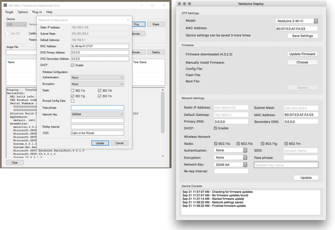
If you’re using the Netduino 3 WiFi model, the authentication and encryption options can be a little confusing, however, if you’re connecting to a modern WiFi network that requires a password, you’ll likely need to set the Authenticationsetting to Shared, and the Encryption setting to WPA. Additionally, SSID refers to the name of the WiFi network.
Testing the Application/Control Server API
Once the network is configured and the application is deployed, it’s ready to test. If all goes well, the Application Output window in Visual Studio, should have something the following:
- Getting all the network interfaces.
- Found 802.11 WiFi Interface
- MAC Address: 60-D7-E3-A0-02-CB
- DHCP enabled: True
- Dynamic DNS enabled: False
- IP Address: 0.0.0.0
- Subnet Mask: 0.0.0.0
- Gateway: 0.0.0.0
- SSID:Cabin in the Woods
- Found 802.11 WiFi Interface
- No IP Address
- DHCP is enabled, attempting to get an IP Address
- Sleep while obtaining an IP
- Sleep while obtaining an IP
- Sleep while obtaining an IP
- Got IP Address: 172.16.42.8
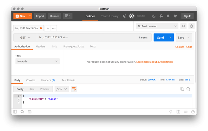
You’ll need the IP address to test the API endpoint. The Status endpoint is easy to test via a browser; make sure you’re on the same network as the Netduino and open up a browser window and navigate to http://[IP Address]/Status. It should display a JSON response. However, I recommend getting Postman to test the endpoints. It’s free and designed specifically to test RESTful interfaces. It allows you to do POST requests in addition to GET, as well as a myriad of other useful things, including automatically parsing JSON responses:
Next Up – Mobile App
Stay tuned for more. In the next part, we’re going to build a Xamarin.Forms app to control our connected coffee maker from bed.
Part 4: Mobile App, Powered by Xamarin
In part 3, we enabled our connected coffee maker to be controlled via a Web API using Maple Server. In this part, we’re going to explore how to easily create a mobile app that runs on iOS, Android, and Windows, powered by Xamarin.Forms that connects to and controls the coffee maker remotely, from the palm of your hand
You can find the source code for the application in our Netduino_Samples repo.
Xamarin.Forms
Despite the fact that the app runs on iOS, Android, and Windows, it has very little code and is incredibly simple, owing to the fact that we built it in Xamarin.Forms.Xamarin.Forms is a technology that allows you to create native applications that run on multiple platforms using a single codebase. For many projects, virtually all of the code is shared between the platforms. Additionally, thanks to Microsoft, Xamarin.Forms is available for free via the Visual Studio Community Edition.
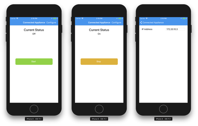
UI Code
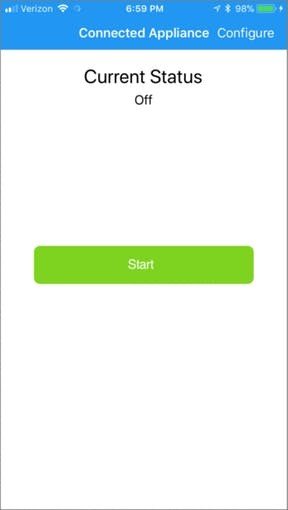
The app has two screens; the home screen which displays the status of the connected coffee maker, and a button to turn it on and off, as well as a configure screen where you can enter the IP address of the appliance to control:
Home Page XAML
We’ve built the UI using XAML, a declarative UI markup language which makes complex layouts simple, and allows a clear separation between the page logic/functionality, and the element rendering.
Our homepage is nested in a ContentPage which provides automatic navigation. Xamarin.Forms will render elements as their native types on each platform, but we wanted to customize the look of our elements, so much of the code is sizing and color modifications. Additionally; we customized the navigation toolbar to add our “Configure” button using the ToolbarItemscollection:
<?xml version="1.0" encoding="UTF-8"?>
<ContentPage xmlns="http://xamarin.com/schemas/2014/forms"
             xmlns:x="http://schemas.microsoft.com/winfx/2009/xaml"
             x:Class="ApplianceRemote.StatusPage">
     <ContentPage.ToolbarItems>
         <ToolbarItem Text="Configure" Clicked="Configure_Clicked" />
     </ContentPage.ToolbarItems>
     <ContentPage.Content>
         <StackLayout>
             <Label x:Name="lblHeader" Text="Current Status" HorizontalOptions="Center"
                    FontSize="25" Margin="0, 20, 0, 0"></Label>
             <Label x:Name="lblStatus" HorizontalOptions="Center"></Label>
             <Button x:Name="btnAction" Clicked="Configure_Clicked" Margin="0,175,0,0"
                      Image="ConfigureAppliance.png" />
         </StackLayout>
     </ContentPage.Content>
 </ContentPage>
The code behind for this page is also very simple. We could have probably simplified even more by using Xamarin.Forms bindings, but for clarity, we’re manually setting the UI state and persisting back to our App object. The important methods here are OnAppearing, Configure_Clicked, and UpdateStatus:
- using System;
- using System.Collections.Generic;
- using System.Net;
- using System.Net.Http;
- using Newtonsoft.Json;
- using Newtonsoft.Json.Linq;
- using Xamarin.Forms;
- namespace ApplianceRemote
- {
- public partial class StatusPage : ContentPage
- {
- ApiHelper apiHelper;
- public StatusPage()
- {
- InitializeComponent();
- btnAction.CommandParameter = Commands.Configure;
- this.Title = "Connected Appliance";
- }
- async protected override void OnAppearing()
- {
- if (string.IsNullOrEmpty(App.HostAddress))
- {
- lblStatus.Text = "Not Connected";
- }
- else
- {
- apiHelper = new ApiHelper(App.HostAddress);
- lblStatus.Text = "Connecting to " + App.HostAddress;
- App.IsConnected = await apiHelper.Connect();
- if(App.IsConnected)
- {
- if (await apiHelper.CheckStatus())
- {
- App.ApplianceStatus = ApplianceStatus.On;
- }
- else
- {
- App.ApplianceStatus = ApplianceStatus.Off;
- }
- }
- UpdateStatus();
- }
- }
- async void Configure_Clicked(object sender, EventArgs e)
- {
- if(sender is Button)
- {
- var s = (Button)sender;
- if (s.CommandParameter.ToString() == Commands.Configure.ToString())
- {
- await Navigation.PushAsync(new ConfigurePage());
- }
- else if (s.CommandParameter.ToString() == Commands.TurnOn.ToString())
- {
- if (await apiHelper.TurnOn())
- {
- UpdateStatus();
- }
- }
- else if (s.CommandParameter.ToString()== Commands.TurnOff.ToString())
- {
- if (await apiHelper.TurnOff())
- {
- UpdateStatus();
- }
- }
- else
- {
- throw new ArgumentException();
- }
- }
- else
- {
- await Navigation.PushAsync(new ConfigurePage());
- }
- }
- void UpdateStatus()
- {
- if (!App.IsConnected)
- {
- lblStatus.Text = "Not Connected";
- btnAction.CommandParameter = Commands.Configure;
- btnAction.Image = "ConfigureAppliance.png";
- }
- else if (App.ApplianceStatus == ApplianceStatus.On)
- {
- lblStatus.Text = "On";
- btnAction.CommandParameter = Commands.TurnOff;
- btnAction.Image = "Stop.png";
- }
- else
- {
- lblStatus.Text = "Off";
- btnAction.CommandParameter = Commands.TurnOn;
- btnAction.Image = "Start.png";
- }
- }
- }
- public enum Commands{
- Configure,
- TurnOn,
- TurnOff
- }
- }
OnAppearing
OnAppearing is called just before the page is displayed to the user and presents an opportunity to update the screen with any new state information. In our case, we check to see if we’re connected to the appliance and display the appropriate connection and on/off state information.
Configured_Clicked
Both the toolbar Configure button, and the main button on the home page call the Configure_Clicked clicked method. First we check to see if it was a button or a toolbar item that called it. If the main button called it, we check the command state to see whether the coffee maker should be turned on or off, and then make the appropriate call, depending on that state. If the toolbar item called the method, then we simply push the configuration page on the navigation stack.
UpdateStatus
The UpdateStatus method is called by both OnAppearing and Configure_Clicked, and has two purposes; it updates the UI with the appliance state, and it keeps the command parameter in synch with the appliance state.
Configure Page XAML
The configure page allows us to set an IP of the connected appliance to communicate with:
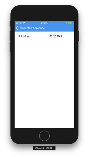
It’s even simpler than the home page, and has a single entry for the IP address:
<?xml version="1.0" encoding="UTF-8"?>
<ContentPage xmlns="http://xamarin.com/schemas/2014/forms"
             xmlns:x="http://schemas.microsoft.com/winfx/2009/xaml"
             x:Class="ApplianceRemote.ConfigurePage">
     <ContentPage.Content>
         <StackLayout Orientation="Horizontal" Padding="20,20,20,20">
             <StackLayout>
                 <Label Text="IP Address"></Label>
             </StackLayout>
             <StackLayout HorizontalOptions="EndAndExpand">
                 <Entry x:Name="IPAddressEntry" Placeholder="0.0.0.0"
                         Keyboard="Numeric" TextChanged="IPAddressEntry_TextChanged"
                         WidthRequest="150" />
             </StackLayout>
         </StackLayout>
     </ContentPage.Content>
 </ContentPage>
Again, the code behind for this uses manual UI updates instead of binding for clarity:
- using System;
- using System.Collections.Generic;
- using Xamarin.Forms;
- namespace ApplianceRemote
- {
- public partial class ConfigurePage : ContentPage
- {
- public ConfigurePage()
- {
- InitializeComponent();
- IPAddressEntry.Text = App.HostAddress;
- }
- void IPAddressEntry_TextChanged(object sender, EventArgs e)
- {
- App.HostAddress = ((TextChangedEventArgs)e).NewTextValue;
- }
- }
- }
Web API Access Code
The final, and most important part of the code is the ApiHelper class, which is responsible for actually communicating with the Web API.
- using System;
- using
Code
Credits
Related products


Leave your feedback...