
Picofarmled - Led Panels For Diy Home Farming Projects

Made by stant / Home Automation / Lights / Plants / IoT
About the project
The first DIY-focused full spectrum LED panels for plants and fishes. Its on-board driver makes is very easy to control from any 3.3v or 5v controller, or even a simple potentiometer. Add the sun to your home farming projects!
Project info
Difficulty: Easy
Estimated time: 1 hour
License: GNU General Public License, version 3 or later (GPL3+)
Items used in this project
Hardware components


Story
Welcome to PicoFarmLED!
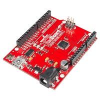
In this little guide we will go through setting up the PicoFarmLED panel with arduino.
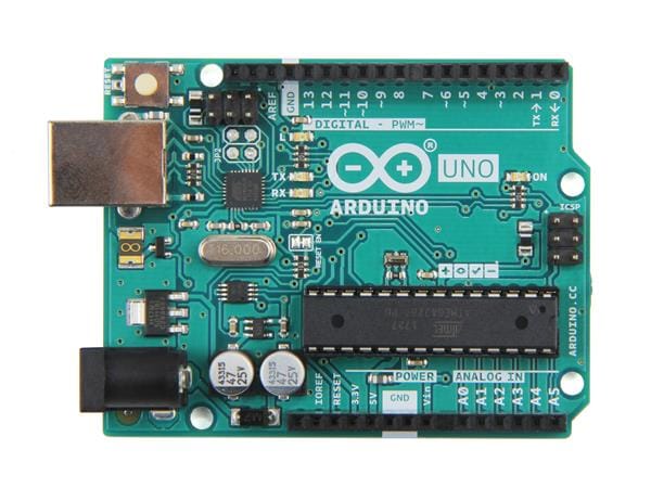
Any arduino compatible board should work, just make sure it's either 3.3v or 5v with PWM output. Which is probably the case of 90% of them.
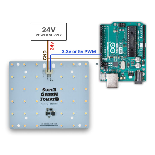
Here is the final schematic we want to have at the end.
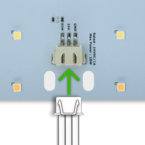
Insert white wire
First thing to do is insert the white wire included in the kit.
FYI: It's a JST-XH 3-pins.
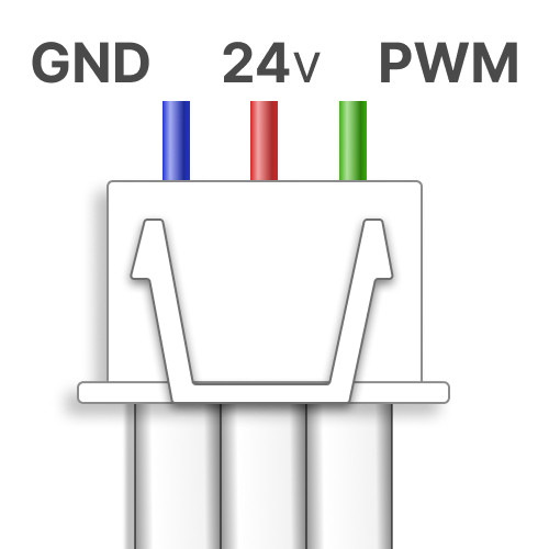
White wire pinout
Here's the pinout on the other end of the white wire once plugged in.
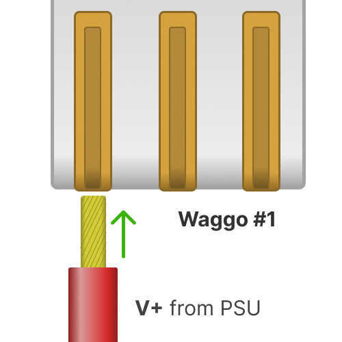
Wago #1 - 24v wires
Ok let's first setup the 24v wire.
Take the first wago plug and insert the V+ wire coming from the power supply.
Checkout the guides below to see how to prepare your power supply.
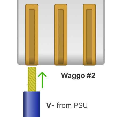
Wago #2 - Ground wires
Now take the second wago plug and insert the ground wire from the power supply.
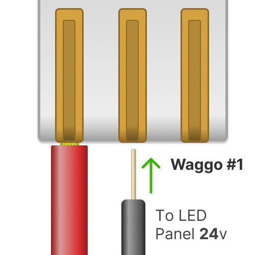
Wago #1 - LED 24v power
Ok, now we have our power wagos setup.
Let's plug the 24v power to the LED panel.
Make sure to use the right pin in the white wire!
24v is the middle pin
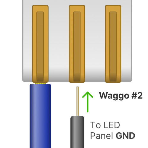
Wago #2 - LED ground wire
Now take the Ground wago.
Add a jumper wire between the arduino GND gpio and the V- pin of the white wire.
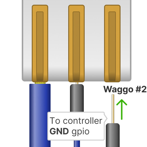
Wago #2 - controller ground
Alright, now we need to link the GND from the system to the controller.
Add a jumper wire to the Wago #2, and plug that jumper to a GND gpio of your arduino.
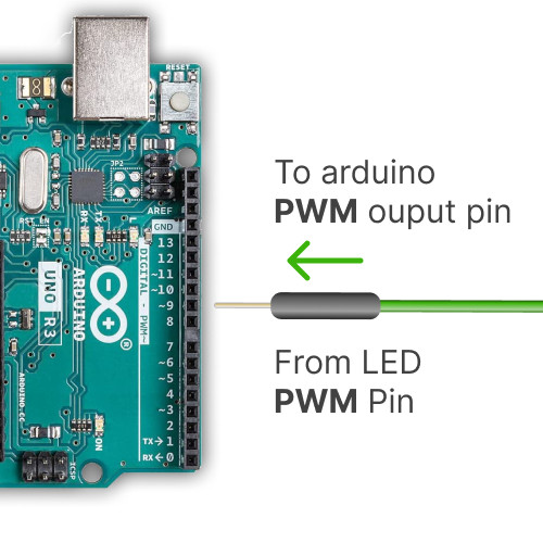
Arduino GND gpio
And now we're going to plug the controlling jumper.
Add a jumper wire to the pin 9, then plug that jumper wire to the white wire hole named "PWM".
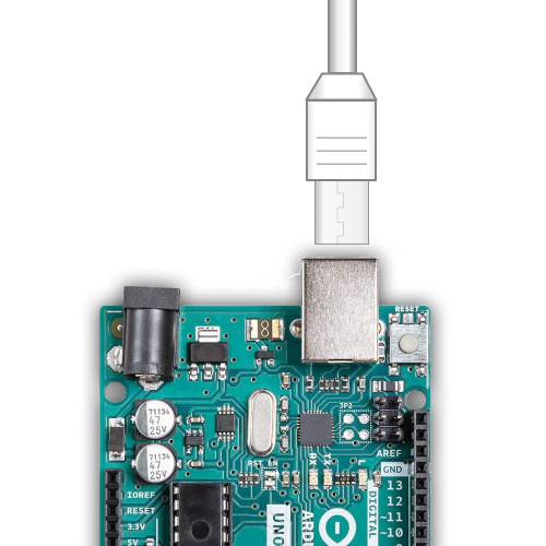
Connect the arduino USB to your computer
Ok so now, keep the 24v power supply unplugged.
Plug your arduino to your computer.
Then start the arduino IDE program.
You can find a link to install it below.
Let's make the panel "breath"
Ok, now we have our arduino IDE started.
Go to Tools -> boards and select your board by its name.
Then in Tools -> Port, select the COM port for the port for your board (its name should be next to it).
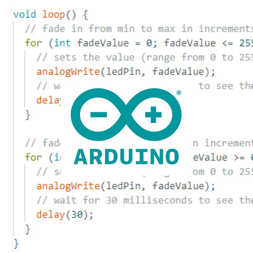
Then go to File -> Examples -> 03.Analog -> Fading.
Make sure the first line is:
`int ledPin = 9;`
If the number is different, move the control wire to the gpio with that number.
Press the "Play" button top right in the arduino IDE to test your setup.
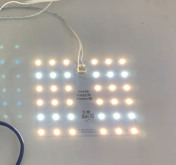
Let there be light!
And now we're ready to turn on the PicoFarmLED panel.
Plug the 24v power supply, and watch your panel come to life:)
And now what?
Ok so now you have a starting point to automate your panel:)
If you don't feel like doing everything yourself and would rather start from something more complete, that will manage timer schedules, sensor monitoring and much more from a web interface?
Checkout our other guides at: https://picofarmled.com/guides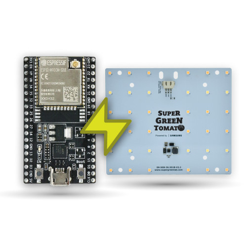
Have fun ? !
Credits
Related products


Leave your feedback...