
Nrf24l01 Wireless Servo Motor Control With Joystick

Made by Ron / Home Automation / Robotics / Sensors / IoT
About the project
In this tutorial we will explore Wireless Communication and learn how to control servo motors using the NRF24L01 modules, joystick.
Project info
Difficulty: Easy
Estimated time: 1 hour
License: GNU General Public License, version 3 or later (GPL3+)
Items used in this project
Hardware components

Story
Step 1: What You Will Need
1 / 4
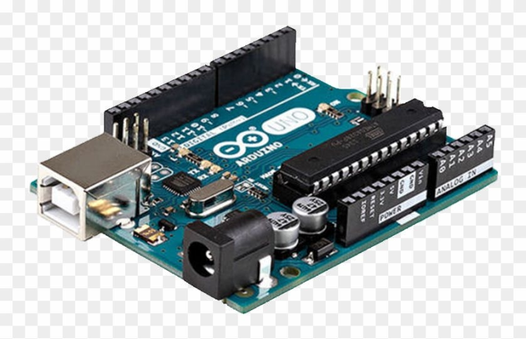
- 2X Arduino UNO (or any other Arduino)
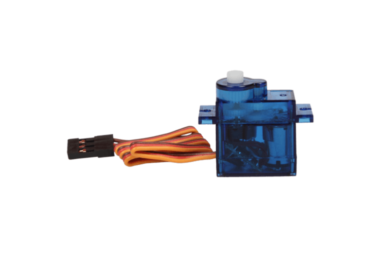
- 2X Servo motor (you can also just use one in case you do not have 2 servo motors)
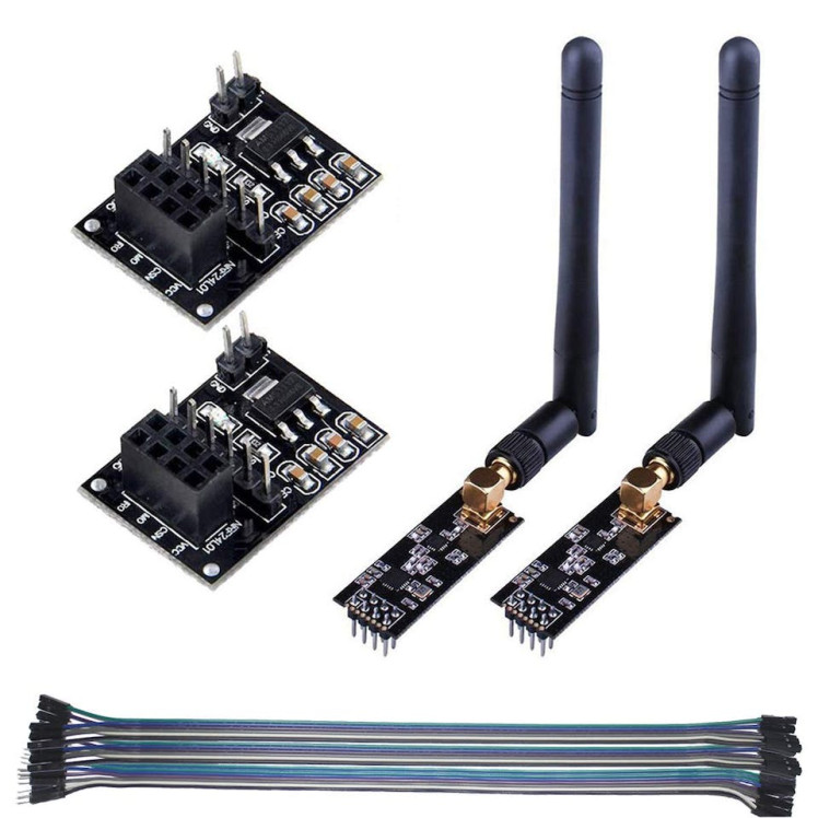
- 2X nrf24l01 module
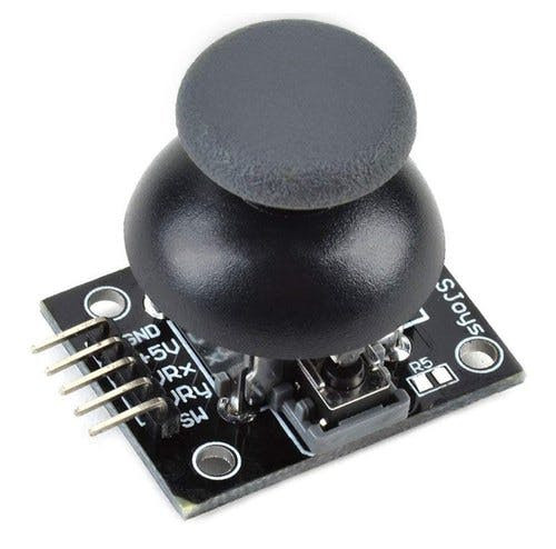
- Joystick module
- Jumper wires
- Visuino program: Download Visuino

Thank you PCBWay for supporting this tutorial and helping users learn more about electronics.
What I like about the PCBWay is that you can get 10 boards for approximately $5 which is really cost effective for professional made boards, not to mention how much time you save!
Go check them out here. They also offer a lot of other stuff in case you might need it like assembly, 3D printing, CNC machining and a lot more.

For this project we are using a NRF24L01 module together with a voltage adapter.
Wiring the Sender Arduino:
- Connect NRF24L01 Adapter pin [VCC] to Arduino pin [5V]
- Connect NRF24L01 Adapter pin [GND] to Arduino pin [GND]
- Connect NRF24L01 Adapter pin "Chip Enable" [CE] to Arduino Digital pin [9]
- Connect NRF24L01 Adapter pin "Chip Select" [CSN] to Arduino Digital pin [10]
- Connect NRF24L01 Adapter pin [SCK] to Arduino Digital pin [13]
- Connect NRF24L01 Adapter pin [MO] to Arduino Digital pin [11]
- Connect NRF24L01 Adapter pin [MI] to Arduino Digital pin [12]
- Connect Joystick pin [VCC] to Arduino pin [5V]
- Connect Joystick pin [GND] to Arduino pin [GND]
- Connect Joystick pin [VRX] to Arduino analog pin [A0]
- Connect Joystick pin [VRY] to Arduino analog pin [A1]
Wiring the Receiver Arduino:
- Connect NRF24L01 Adapter pin [VCC] to Arduino pin [5V]
- Connect NRF24L01 Adapter pin [GND] to Arduino pin [GND]
- Connect NRF24L01 Adapter pin "Chip Enable" [CE] to Arduino Digital pin [9]
- Connect NRF24L01 Adapter pin "Chip Select" [CSN] to Arduino Digital pin [10]
- Connect NRF24L01 Adapter pin [SCK] to Arduino Digital pin [13]
- Connect NRF24L01 Adapter pin [MO] to Arduino Digital pin [11]
- Connect NRF24L01 Adapter pin [MI] to Arduino Digital pin [12]
- Connect Servo Motor1 pin [VCC] to Arduino pin [5v]
- Connect Servo Motor1 pin [GND] to Arduino pin [GND]
- Connect Servo Motor2 pin [VCC] to Arduino pin [5v]
- Connect Servo Motor2 pin [GND] to Arduino pin [GND]
- Connect Servo Motor1 pin [S] to Arduino Digital pin [2]
- Connect Servo Motor2 pin [S] to Arduino Digital pin [3]
1 / 2
The Visuino: https://www.visuino.eu also needs to be installed. Download Free version or register for a Free Trial.
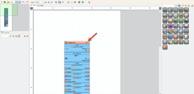
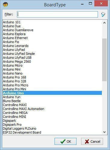
Start Visuino as shown in the first picture Click on the "Tools" button on the Arduino component (Picture 1) in Visuino When the dialog appears, select "Arduino UNO" as shown on Picture 2
Step 5: For Sender Arduino - in Visuino Add, Set & Connect Components1 / 6

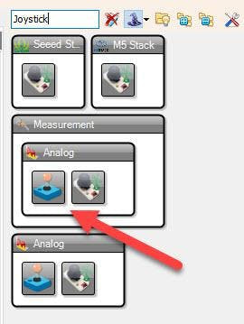
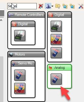
- Add "Joystick" component
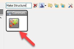
- Add "Make Structure" component
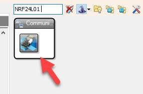
- Add "NRF24L01 Wireless" component
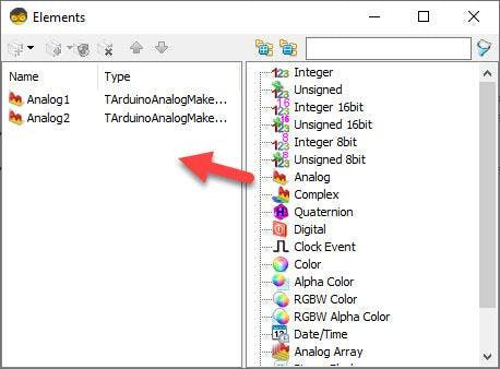
- Double click on the "MakeStructure1" and in the "Elements" window drag 2X "Analog" to the Left side
- Close the "Elements" window
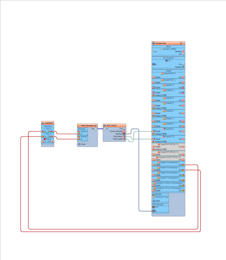
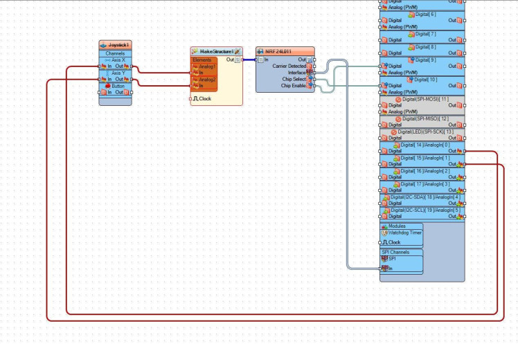
- Connect Arduino Analog pin [0] to "Joystick1" > "Axis X" pin [In]
- Connect Arduino Analog pin [1] to "Joystick1" > "Axis Y" pin [In]
- Connect "Joystick1" > "Axis X" pin [Out] to "MakeStructure1" > "Analog1" pin [In]
- Connect "Joystick1" > "Axis Y" pin [Out] to "MakeStructure1" > "Analog2" pin [In]
- Connect "MakeStructure1" pin [Out] to "NRF24L011" pin [In]
- Connect "NRF24L011" pin Interface [SPI] To Arduino board pin [SPI]
- Connect "NRF24L011" pin [Chip Select] To Arduino board digital pin [10]
- Connect "NRF24L011" pin [Chip Enable] To Arduino board digital pin [9]
Upload the Project to the Arduino Board (see the Generate, Compile, and Upload the Arduino Code step)
Step 6: For Receiver Arduino - in Visuino Add, Set & Connect Components1 / 6
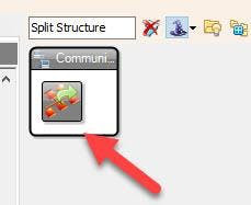

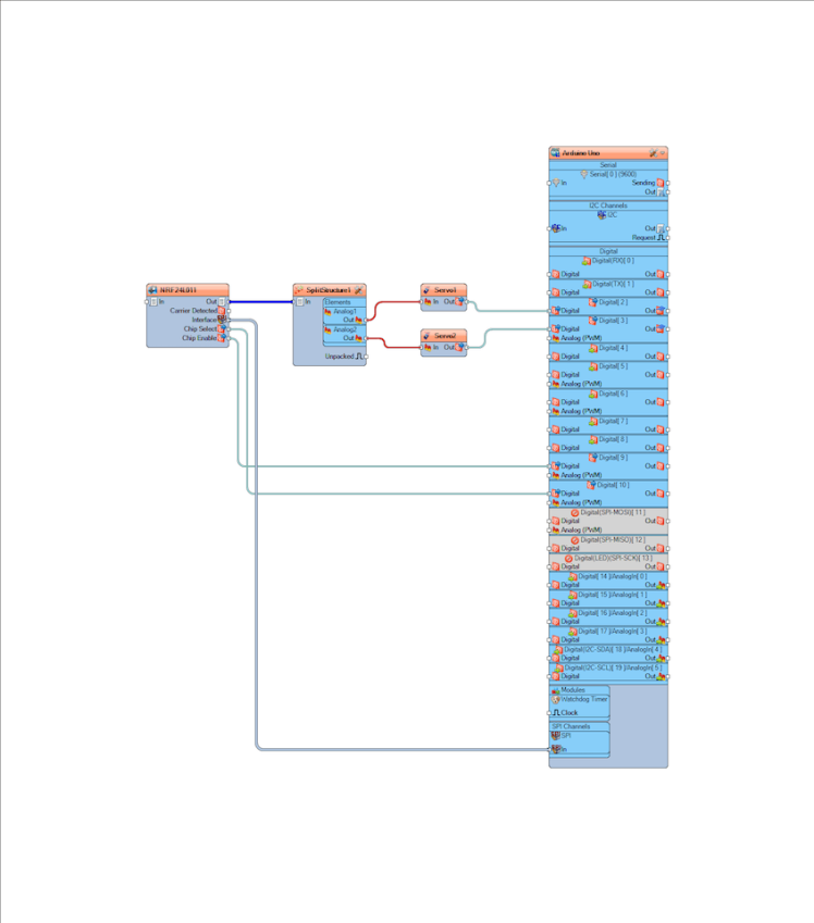
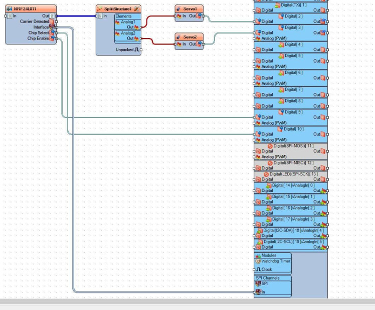
- Add "Split Structure" component
- Add 2X "Servo" component
- Add "NRF24L01 Wireless" component
- Double click on the "SplitStructure1" and in the "Elements" window drag 2X "Analog" to the Left side
- Close the "Elements" window
- Connect "NRF24L011" pin Interface [SPI] To Arduino board pin [SPI]
- Connect "NRF24L011" pin [Chip Select] To Arduino board digital pin [10]
- Connect "NRF24L011" pin [Chip Enable] To Arduino board digital pin [9]
- Connect "NRF24L011" pin [Out] to "SplitStructure1" pin [In]
- Connect "SplitStructure1" > "Analog1" pin [Out] to "Servo1" pin [In]
- Connect "SplitStructure1" > "Analog2" pin [Out] to "Servo2" pin [In]
- Connect "Servo1" pin [Out] to Arduino board digital pin [2]
- Connect "Servo2" pin [Out] to Arduino board digital pin [3]
Upload the Project to the Arduino Board (see the Generate, Compile, and Upload the Arduino Code step)
Step 7: Generate, Compile, and Upload the Arduino Code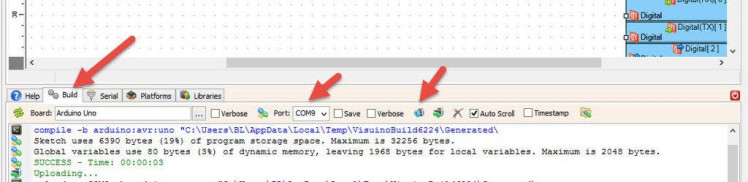
In Visuino, at the bottom click on the "Build" Tab, make sure the correct port is selected, then click on the "Compile/Build and Upload" button.
Step 8: PlayIf you power the Arduino modules, and move the joystick the servo motors connected to the Receiver Arduino will start to move.
Congratulations! You have completed your project with Visuino. Also attached are the Visuino project files for Sender and Receiver, that I created for this Tutorial, you can download it and open it in Visuino: https://www.visuino.eu
Schematics, diagrams and documents
Code
Credits
Related products


Leave your feedback...