
No-code Intrusion Detection System With Blues Notecard

Made by knaveen / Home Automation / Notifications / Security / Sensors / IoT
About the project
You can have an AIoT security system up and running with minimal configuration, without the need to write any code.
Project info
Difficulty: Easy
Platforms: Seeed Studio, M5Stack, Blues Wireless
Estimated time: 5 hours
License: MIT license (MIT)
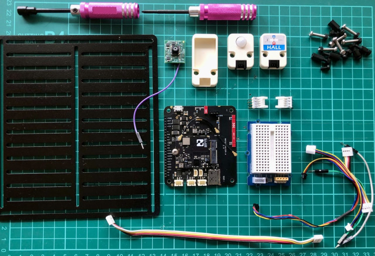
Items used in this project
Hardware components

View all
Story
Alarm systems for intruders are typically associated with museums and wealthy individuals. However, I don't see the need for one in my home as it's unlikely that anyone would attempt to break in.
Despite the common belief that domestic burglaries are decreasing, the reality is quite the opposite. Every year, countless normal homes and small businesses fall victim to these crimes. To tackle this issue, I am working on a project to develop an AIoT-based Intrusion Alarm System that can safeguard any environment from unauthorized access or intrusion. By utilizing affordable sensors, the system can effectively monitor the area and identify any unusual activities, such as motion, open doors, or the presence of individuals. In the event of an intrusion, the system can immediately notify the user or authorities through text messages, emails, or notifications.
Set up hardware
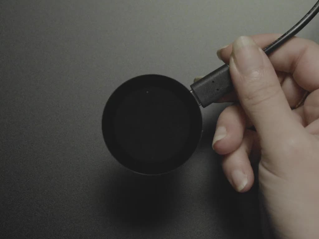
For this project, we need network connectivity that is dependable, energy-efficient, and simple to handle. To achieve this, we will employ the Blues Wireless Wi-Fi Notecard, along with the Notecarrier A and the necessary sensors (which are specified in the following section). Our objective is to demonstrate how the Blues Wireless Wi-Fi (or cellular) Notecard can utilize sensors without requiring a host MCU.
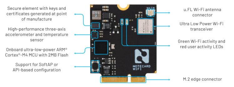
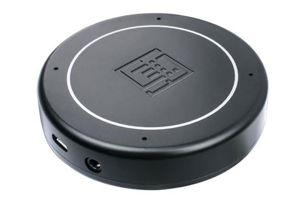
Wi-Fi Notecard
The Wi-Fi Notecard is a version of the Blues Wireless Notecard with Wi-Fi connectivity in place of cellular. The device is the same size as all cellular Notecards and follows the same M.2 pinout. Wi-Fi Notecards can connect to Wi-Fi access points and transmit data over Wi-Fi networks. For this undertaking, we will employ a Wi-Fi Notecard to transmit information to a cloud service.
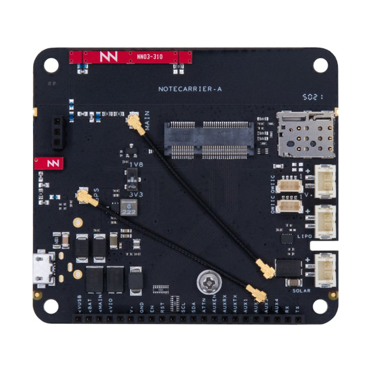
Notecarrier A
The Notecarrier A offers breakout connections for the Notecard, as well as circuitry, to provide power management, protection, and signal amplification. The Notecard is designed to be socketed directly onto the circuit board using an edge connector socket.
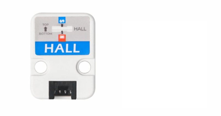
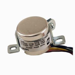
Hall effect Unit
Hall effect Unit is integrated with three A3144E Hall sensor switches which are processed by 74HC series gate integrated circuits. When the south pole of a magnet is near the top of the sensor or the north pole is near the back, the sensor's digital output pin will read low; otherwise, it will read high. To determine if a door is open, simply place this sensor near a magnet attached to the door. Once the door is opened, the sensor output pin will register as high.
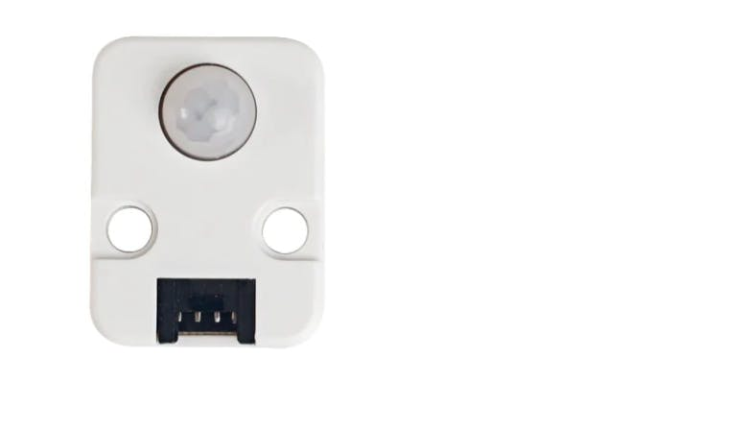
PIR Motion Sensor
The PIR (Passive Infrared) motion sensor is capable of detecting the infrared radiation that is emitted and reflected by humans or objects. It produces a high output level when infrared is detected, with a 2-second delay time to allow for debouncing.
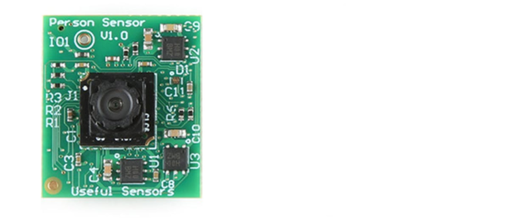
Person Sensor
Useful Sensors' Person Sensor is a compact hardware module designed to detect the faces of individuals nearby. It provides details on the number of people present, and their location in relation to the device, and even performs facial recognition. The board uses a standard Qwiic connector for the I2C interface.
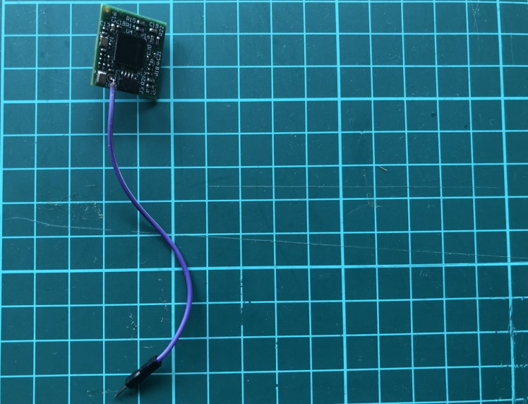
To detect people, we will utilize a distinct interrupt pin on the board. The Qwiic connector will solely power the board. To read the interrupt's status, we must solder a jumper wire.
Hardware Assembly
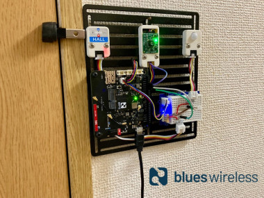
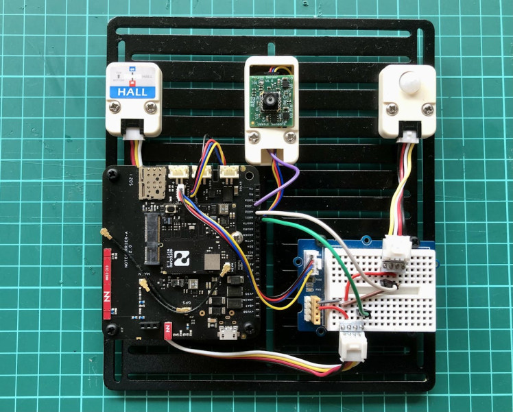
Place the Notecard into the M.2 slot on the Notecarrier A gently and tighten it using the provided screw to secure it. Secure the free end of the u.FL cable connected to the socket labeled MAIN on the Notecarrier to the MAIN socket on the Notecard. We are using a Grove - Breadboard to distribute the 3.3V/GND power connection from the Notecarrier A's Qwiic connector. The Person Sensor is being powered directly from another Qwiic connector at Notecarrier A. All components are mounted to a prototyping plate. Since the prototyping plate is made up of Aluminium alloy, we have used an M5Stack Plastic Case for Proto Unit to protect and mount the Person Sensor. The assembled hardware looks like the image below.
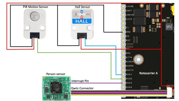
The Hall sensor and PIR motion sensor's output pins are connected to the AUX1 and AUX2 respectively. The Person sensor's interrupt pin is connected to the AUX3 pin. The connection diagram is given below.
Set up software and development environment
For this project, we are not going to write a single line of code so we do not have to install any software or set up a development environment. We just need to provide some configuration using web-based applications.
Notecard Configuration
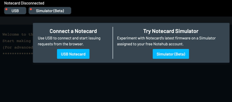
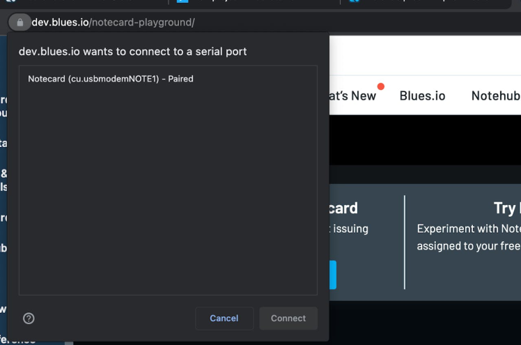
First, connect the Notecarrier A to a computer via USB. We should see a red LED flash repeatedly while it's booting up. We will be using the in-browser REPL to configure the Wi-Fi Notecard which can be accessed at https://dev.blues.io/notecard-playground. Click on the USB Notecard and pair the device as shown in the images below.
We would be able to see the REPL after a successful pairing.
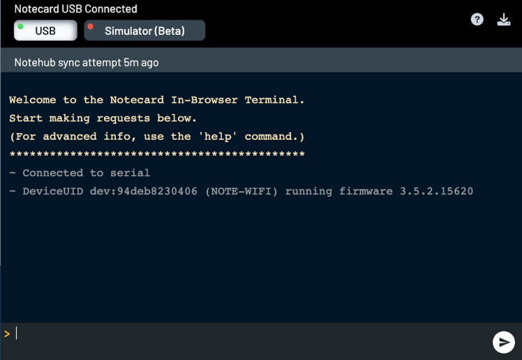
Now write the request below (in the text field above) and send it (by clicking the paper plane button) to the Wi-Fi Notecard to connect to the access point.
{
  "req": "card.wifi",
  "ssid": "<ssid>",
  "password": "<password>"
}
When the Wi-Fi Notecard is actively connected to Notehub the green LED turns on. We can send the request below to verify the connection.
{
  "req": "card.wireless"
}
Set up Notehub
We need to set up Notehub, which is a cloud service that receives data from the Notecard and allows us to manage the device, and route that data to our own or 3rd party cloud apps and services. We can create a free account at https://notehub.io/sign-up, and after successful login, we can create a new project.
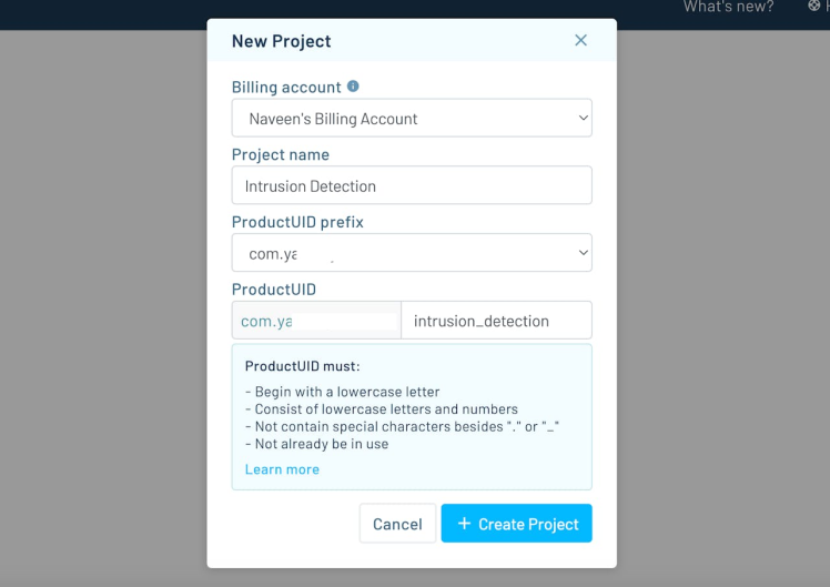
We should copy the ProductUID which is used by Notehub to associate the Notecard to the project created. To set the ProductUID, we need to send the request below to the Notecard.
{
  "req": "hub.set",
  "product": "<ProductUID>"
}
We can validate the Notecard configuration by performing a manual synchronization to Notehub.
{
  "req": "hub.sync"
}
Once a sync has started, we can check on the state of the sync with the request below.
{
  "req": "hub.sync.status"
}
Configure AUX Pins
The Notecard edge connector provides a series of auxiliary pins that we can utilize to build a no-code application. The behavior of these pins changes depending on the AUX mode configured on the Notecard. We will configure the AUX pins in GPIO mode. In this mode, the AUX1-AUX4 pins are used as general-purpose I/O pins. AUX GPIO mode is enabled with the value gpio in the mode argument of a card.aux request. The following request configures the first 3 AUX pins as a pull-down input.
{
  "req":     "card.aux",
  "mode":    "gpio",
  "usage":   [
    "input-pulldown",
    "input-pulldown",
    "input-pulldown",
    "off"
  ],
  "sync": true,
  "file": "detection.qo"
}
With the above request, the Notecard will automatically report any state changes on AUX1, AUX2, and AUX3 pins. The Notecard applies about one second of debounce to any GPIO transition and on state changes adds a Note to the Notefile detection.qo specified by file key and immediately syncs with Notehub.
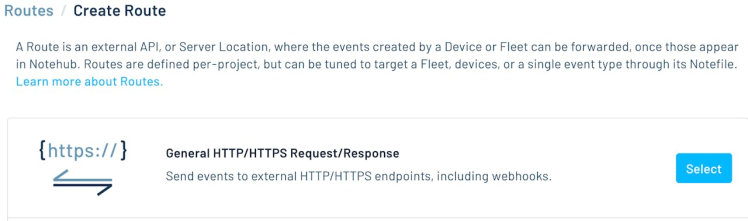
Route Configuration
For this proof-of-concept project, we would not need to send any text messages or email notifications but we will be displaying the live sensors' status using the Initial State, a data streaming and visualization tool that's easy to set up and configure. We would need to create a trial Initial State account. To create a Route in Notehub, we can find the Initial State API Key by clicking on the Manage My Settings link on the dashboard and the default access key under the Access Keys heading. We will create two routes one by one; Initial State Provisioning and Initial State Data by going to Routes > Create Route page and selecting the General HTTP/HTTPS Request/Response.
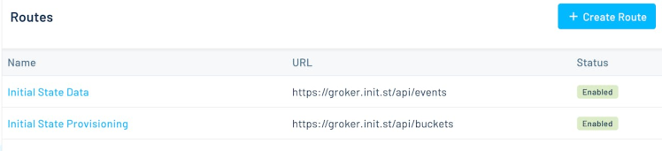
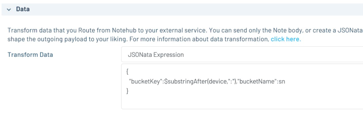
The first route provisions the device with its Initial State and creates a bucket to hold event data. This route will only run once per session when Notehub sees a _session.qo file from the Notecard. The second route runs whenever the Notecard syncs and adds sensor data to the Initial State bucket. Please follow the detailed and comprehensive documentation provided by Blues Wireless to set up routes for the Initial State. For the Initial State Provisioning route, in the Transform JSON field, select JSONata (a query and transformation language for JSON data) Expression and enter the expression as shown in the image below to set the DeviceUID as the bucketKey and Device Serial Number as the bucketName:
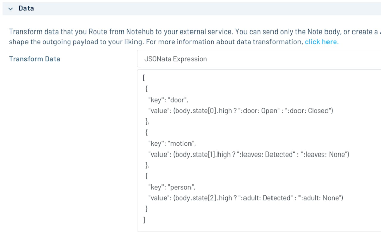
For the Initial State Data route, in the Transform JSON field, select JSONata Expression and enter the expression as shown in the image below.
Data Visualization
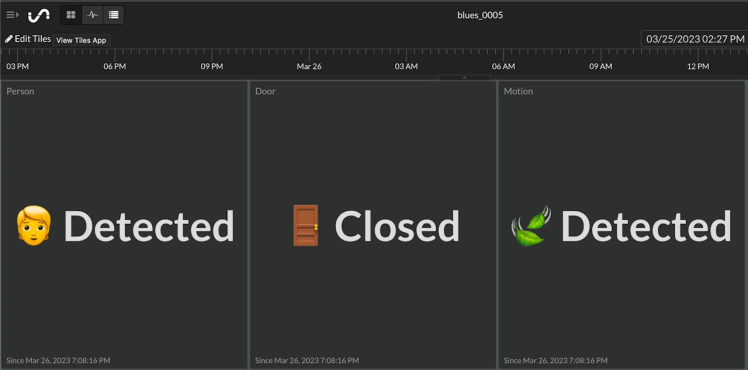
Initial State offers a default tile display for every key (signal) given. The sensor's status is visible as tiles on the Initial State dashboard.
Demo
During the live demo, it was demonstrated that the Notecarrier A can be powered through its USB connector. However, it is also possible to power the Notecarrier A using a single-cell (3.7V) Lipo battery and a 4.5-7V solar panel.
Conclusion
There is a myriad of possibilities to create a similar low-powered project with other sensors for different use cases without writing any code and without any host MCU. The project requires minimal or no maintenance and the sensors can be replaced easily with similar output pins behavior. Although we have used a Wi-Fi Notecard for this proof-of-concept project, we can effortlessly change it with a drop-in replacement cellular (LTE-M, NB-IoT, or Cat-1) Notecard. If your project requires sending text messages you may find more details in this project.
Schematics, diagrams and documents
Credits
Related products


Leave your feedback...