
Motion Activated Door Thermometer

Made by TheInventorsWorkbench / 3D Printing / Environmental Sensing / Health / Home Automation / Sensors
About the project
I designed this project at the peak of the COVID pandemic in order to check my temperature before leaving the house each day. I could imagine this project being adapted and implemented at bars, restaurants, or airports also.
Project info
Difficulty: Moderate
Estimated time: 3 hours
License: GNU General Public License, version 3 or later (GPL3+)
Items used in this project
Hardware components

View all
Story
I'm sure there are many good ways to build this project entirely from scratch, but I decided to start with a cheap infrared forehead thermometer you can find on amazon.

I started by removing the batteries, popping off the front and back plastic covers, and prying apart the two halves of the body with a screwdriver. There is a hidden screw under the sticker that would have helped me out. This takes a little force but is easy enough with some patience.
Next I desoldered the battery contacts and wired in a AAA battery holder.
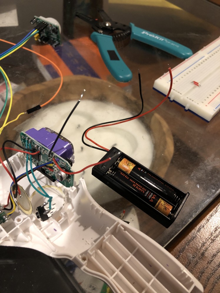
After the battery holder was in place, I desoldered the push button on the thermometer and removed the remaining screws from the infrared unit housing.
Next I wired my motion sensor to my Arduino Nano. Ground to ground, power to 5v and signal to pin D2.
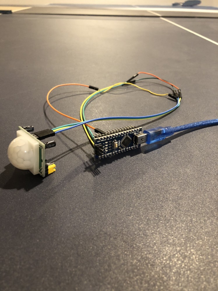
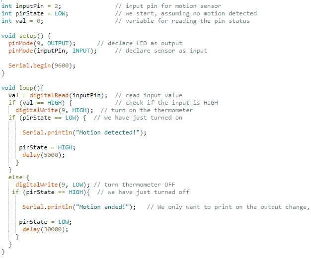
I tested it using the code below. If everything is working correctly, the onboard Arduino LED should light up when you wave your hand in front of the detector.
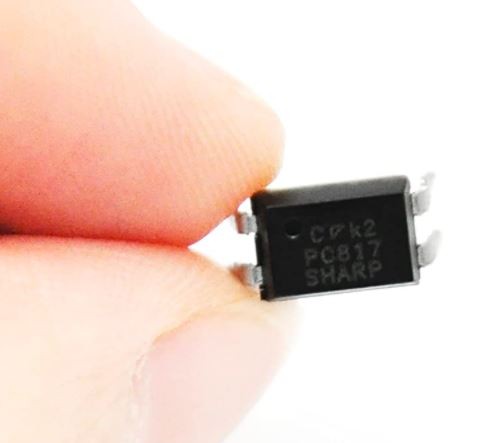
In order to simulate the button being pressed on the thermometer, I used a PC817 Optocoupler. This is just an enclosed phototransistor with an IR LED. When the LED is given power the internal transistor allows current to flow.
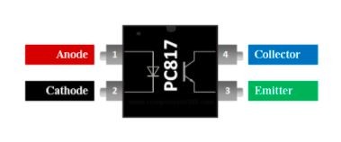
You will need to wire the anode to pin D9 of the Arduino with a 220 Ohm resistor in between. Cathode goes to ground, and the 2 wires from the push button of the thermometer go to collector and emitter.
Finally I connected a 9v battery to the Vin and Ground of the Arduino with an ON/OFF switch in between to give it power.
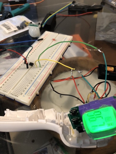
**Be sure to solder the 9V battery to the ON/OFF switch after installing everything else in the housing in the last step. It is fine to test it with a breadboard now**
If I had thought about it earlier I would have used the 9V battery with some resistors to power the thermometer and get rid of the AAAs altogether, but since this is just a prototype, I went ahead and did it this way.
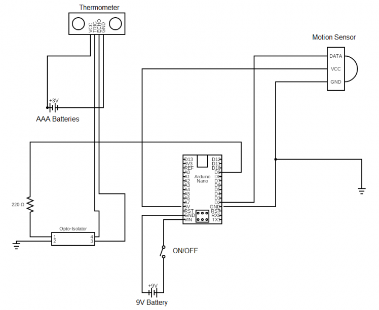
In all, the schematic looks something like this.
I used a small piece of prototyping perfboard to solder things up cleanly but you can make the connections however makes the most sense to you.
If you wired everything correctly, the code below should make the whole thing work. When the motion sensor detects motion, it will trigger the thermometer to take a reading. It will then pause for 10 seconds. If motion is detected again, another reading will be taken. If no motion is detected, it will turn off after about 30 seconds or so.
The ON/OFF switch is used since the battery will constantly be drained if left on. I am sure there are ways to mitigate this but again, this is just a prototype, so this method was OK for my purposes. If you know a good way to do this, let me know in the comments!

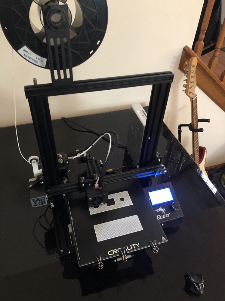
Next it's time to make a housing unit for it all. I decided to design one myself and 3D print it on my Ender 3, but I have used project boxes from amazon in the past, and they work fine for simple things like this. All you will have to do is use a rotary tool or similar to cut the holes for the components.
If you have access to a 3D printer, you can print my files here. This includes a sliding back cover for the unit.
Once you have your project box ready, you will need to use hot glue to install the motion sensor in the top hole, the thermometer screen in the middle hole, and the IR unit in the bottom hole facing out. The ON/OFF switch can be press fit into the hole in the top.
**Once the ON/OFF switch is installed in the box, it can then be soldered to the 9V battery terminals**
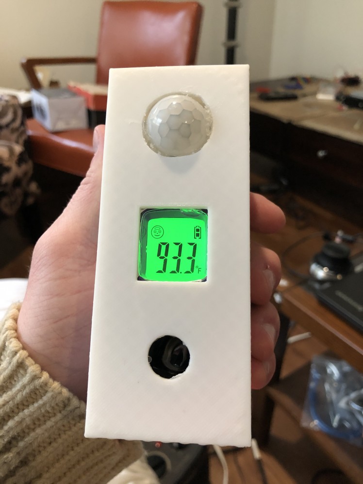
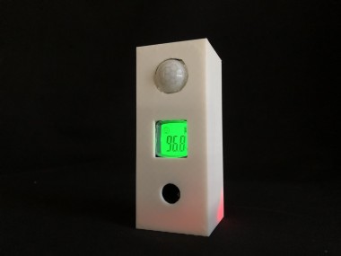
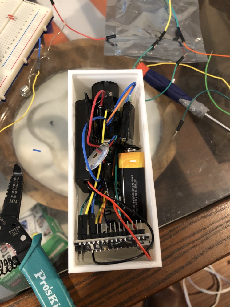
Finally, all the components can be snugly fit into the box (a little messy).
Turn it on and test it to make sure everything is working properly. If everything looks good, go ahead and slide in the back cover and mount this next to your door!
Please let me know if you have any questions about this build, or suggestions for improvements.
Thanks!
Schematics, diagrams and documents
CAD, enclosures and custom parts
Credits
Related products


Leave your feedback...