

Items used in this project
Hardware components

Story
Hello there
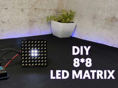
This is a max7219 based 8*8 led matrix. Which is best for simple displaying projects that is we can display letters and numbers. This module comes with just 5 pins Vcc, ground, Data in, cs and CLK that's made the very easy connection between Arduino or similar microcontrollers also we can add multiple matrixes together and make big large matrixes. But did you Ever tired of using this 8*8 led matrix. Because of its colour and shape.? Of course, other colours are available but they are costly and rare. So I decided to build my own 8*8 matrix. It has all the mentioned features and the plus point is we can decide the colour also I changed the traditional round shape of the individual LEDs to square. So In this tutorial, I am showing how I build this custom Arduino compatible 8*8 led matrix. let's get started with this.
COMPONENTS NEEDED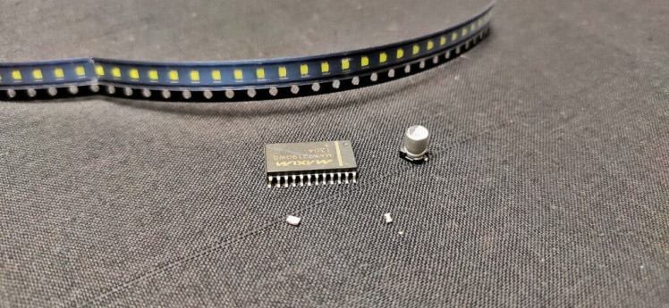
custom PCB
3d printed jig
max 7219 ic
LEDs *64
10 uf capacitor
.1uf 0805 capacitor
10k resistor
CIRCUIT DIAGRAM
The first thing is the circuit here I am going to use max7219 ic for driving the 8*8 matrix. So this is the circuit. Here I connected 64 LEDs in an 8*8 matrix pattern.
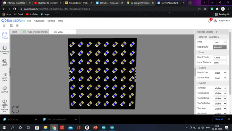
Next, I designed PCB using easyeda and downloaded the Gerber files for PCB fabrication.
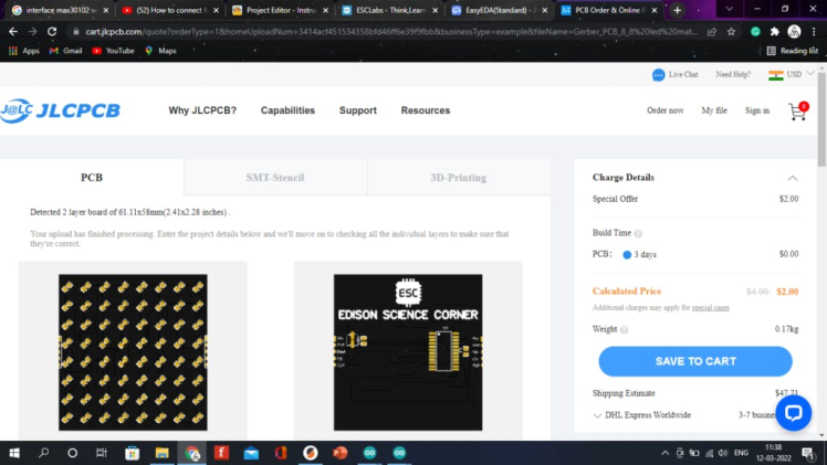
After that, I went to JLCPCB.COM. I choose jlcpcb because they offer only 2 $ for 5 PCBs and their PCB assembly starts from 0$. Next, I uploaded the Gerber file to jlcpcb after selecting the colour and Shipping method I placed the order.
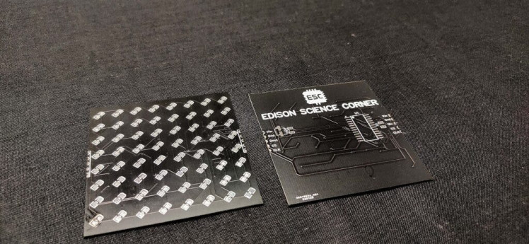
After 2 weeks I received the PCBs and here you can see the PCBs. As always PCB quality is awesome. Here you can see we can cascade multiple matrixes together.
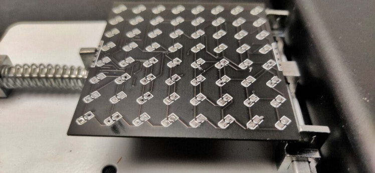
Here we have to solder 64 LEDs. Hand soldering should make pain. So I decided to go with reflow soldering. So first I dispensed the solder paste to the led pads using a needle. Simply because I don't have a solder paste dispenser. Next, I placed 0805 SMD LEDs. I placed 32 LEDs first. Now let's try the reflow. I placed the PCB on the hot plate and I enjoyed the cooking process. This is the result everything is perfect. So I repeated the previous process for the remaining LEDs and made the 8*8 led matrix.
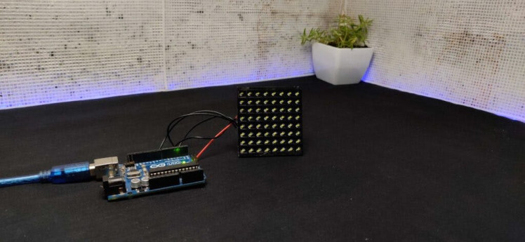
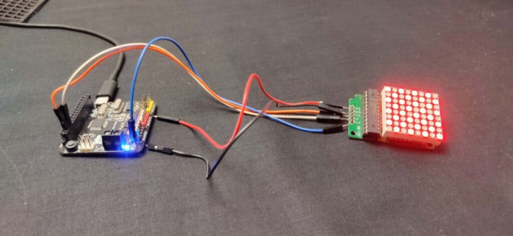
We already soldered one side using the reflow method so Now on the backside, I soldered max 7219 ic and Other SMD components using a normal soldering iron. Finally, I connected wires to VCC, ground, data in, cs and CLK. Now I connected the matrix to Arduino. VCC to 5v ground to ground. Din to pin 12, clock to pin 11, and cs to pin 13.
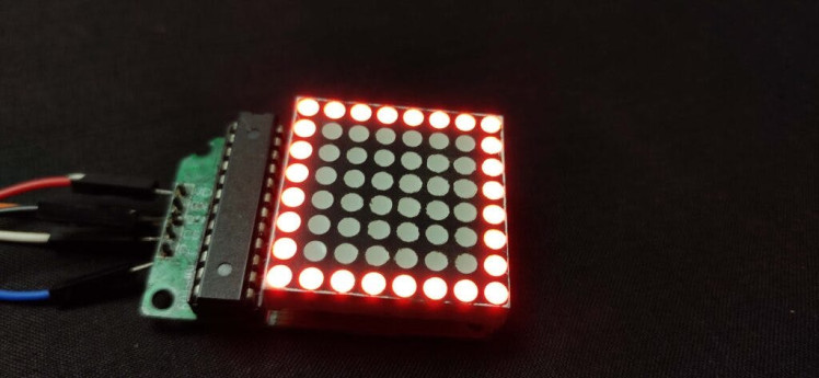
After uploading the code see the result. It worked without any problem.

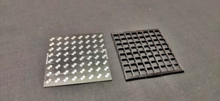
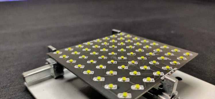
Next, I designed a small 8*8 matrix jig and 3d printed it. After placing the jig over PCB I got a better result. So this is how I made my own 8*8 led matrix. You can buy the custom PCB, Module from here. Watch this making video. Hope you learned something new from my video if so please like, share and subscribe it's all up to you I will see you next time.
Schematics, diagrams and documents
Code
Credits
Related products


Leave your feedback...