
Make Diy Interactive Paper Robot With Hexabitz ???

Made by Aula_Jazmati / Art / Games & Gaming / Kids & Family / Robotics / Sensors
About the project
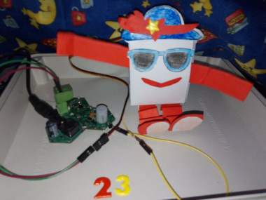
Make a robot that reacts to gestures by waving its arms in a cheer!
Project info
Difficulty: Moderate
Platforms: Adafruit, STMicroelectronics
Estimated time: 1 hour
License: MIT license (MIT)
Items used in this project
Hardware components

Software apps and online services
Story
In this project, we aim to create an interactive paper robot using Hexabitz modules. The robot will be equipped with a servo motor and a motion sensor, enabling it to move its arms and wave in response to any movement detected by the sensor. By combining the versatility of Hexabitz with the simplicity of paper, we hope to create a fun and engaging DIY project that showcases the potential of modular robotics. Whether you're a beginner or an experienced maker, this project is sure to provide a rewarding challenge and a unique addition to your robotics collection. So let's get started and bring this interactive paper robot to life!
Tools:The DIY interactive paper robot with Hexabitz is a project aimed at designing a paper robot for children using servo motors and motion sensors. The robot is capable of moving its arms and waving whenever any movement is detected in front of the sensor.
This project combines creativity, engineering, and technology to create an interactive and engaging experience for children. By using simple materials like paper and basic electronic components, we can build a fun and educational toy that encourages children to explore the world of robotics.
The main components used in this project are servo motor, which allow the robot's arms to move in different directions, and a motion sensor that detects any movement in its vicinity.
The DIY interactive paper robot not only introduces children to basic robotics concepts but also encourages them to think creatively and problem-solve. They can customize their robots by decorating them with colors, patterns, or even adding additional features like LED lights or sound effects.
Through this project, children will learn about basic electronics, coding, and how different components work together to create a functional robot. It provides an opportunity for hands-on learning and fosters curiosity and imagination.
Temperature, Humidity, Light, Color and Motion Sensor Hub:
H0AR9x is sensor hub module with STM32G0 MCU and a variety of sensors:
- Weather: TI HDC1080DMBT digital temperature and relative humidity sensor.
- Light: Broadcom (Avago) APDS-9950 proximity, ambient light and RGB color sensor.
- Motion: Panasonic EKMC1601111 proximity infrared motion detector (PIR).
Use this module as an indoors weather station, room monitoring node or put on board aerial or ground robotics platform to gather surrounding data. Connect with other Hexabitz modules to log sensor measurements, stream data wirelessly or control external devices based on sensor readings.
H0AR9x ModulePanasonic EKMC1601111 proximity infrared motion detector (PIR)
")
Panasonic EKMC1601111 proximity infrared motion detector (PIR)
Panasonic EKMC1601111 proximity infrared motion detector (PIR) characteristics
 characteristics")
Panasonic EKMC1601111 proximity infrared motion detector (PIR) characteristics
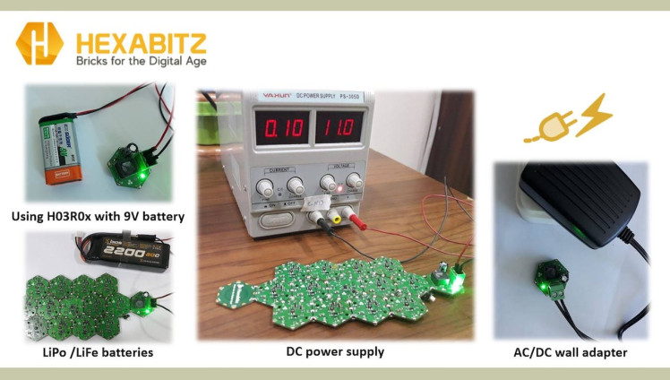
3.3V/1A DC-DC Power Supply (H03R0x):
H03R0x is a compact DC-DC buck power supply with a 3.3V/1A DC output and 5-40V DC input. The output voltage is provided through Hexabitz SMD edge-pad connectors (3.3V on top and GND on bottom). The -T module version comes with a 5.08 mm terminal block connector for input voltage, while the -J comes with a DC power jack. Use this module to power all your Hexabitz creations (and other hardware) from a DC source (battery, AC/DC wall adapter, etc.).
1 / 3 • 3.3V/1A DC-DC Power Supply (H03R0x)
")
3.3V/1A DC-DC Power Supply (H03R0x)
")
3.3V/1A DC-DC Power Supply (H03R0x)
5V DC-DC Boost Power Supply (H32R1x):
H32R1x is a compact DC-DC boost power supply module that takes 3.3V from module array ports and boosts it up to 5V/0.5A output voltage on the terminal block connector. You can use this module to generate 5V from your Hexabitz array 3.3V backbone voltage.
5V DC-DC Boost Power Supply (H32R1x)
")
5V DC-DC Boost Power Supply (H32R1x)
STLINK-V3MODS Programmer (H40Rx):
H40Rx is a programmer module which contains STLINK-V3MODS stand-alone debugging and programming mini probe for STM32 micro-controllers (Hexabitz modules and other MCUs).
It supports the SWD (Serial Wire Debugging) interface for the communication with any STM32 micro-controller located on an application board.
It also provides bridge interfaces to several communication protocols, allowing for instance the programming of the target through boot-loader.
STLINK-V3MODS Programmer (H40Rx)
")
STLINK-V3MODS Programmer (H40Rx)
How I build it ?️Step 1: Plan the array and assemble the hardware:· We prepare the project components and plan our array design by aligning modules side-by-side.
· Then we solder the modules together using Hexabitz Fixture.
The Project Array

The Project Array
CheerBot Template: If you need to print CheerBot templates, you can download them here: https://www.okdo.com/p/okdo-microbit-build-a-paper-robot-kit
CheerBot Template

CheerBot Template
Pre-crease all the fold lines. This will make assembly easier later on.

Pre-crease all the fold lines. This will make assembly easier later on.
Glue or tape the servo in place where shown.

Glue or tape the servo in place where shown.
Tape a servo horn to the middle of the armsStep 2: Writing codes with STM32CubeIDE software:- Check out this article for writing code with STM32CubeIDE.
- Check out this article for Utilize Modules Ports as Independent Controller Ports Outside of BOS System.
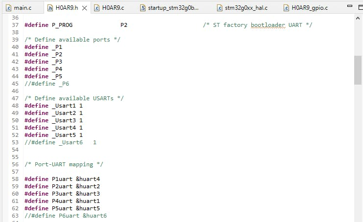
H0AR9x Firmware H0AR9.h code:
First, reduce the number of ports in the.h file. This can be achieved by replacing the original number of ports with one less, and commenting out the last port along with its related USART port and UART Init prototype. For example, if the original number of ports is 6, it should be reduced to 5 by commenting out (//#define _P6), (//#define _Usart6 1), and (//extern void MX_USART6_UART_Init(void);).
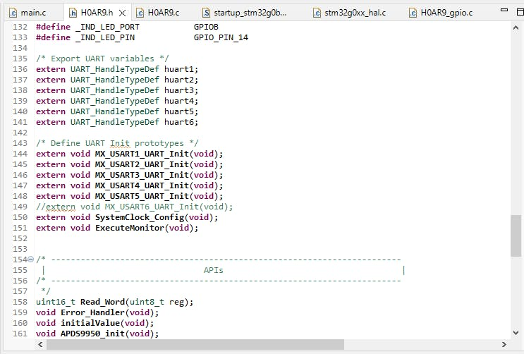
To find out the chosen pin and port

To find out the chosen pin and port
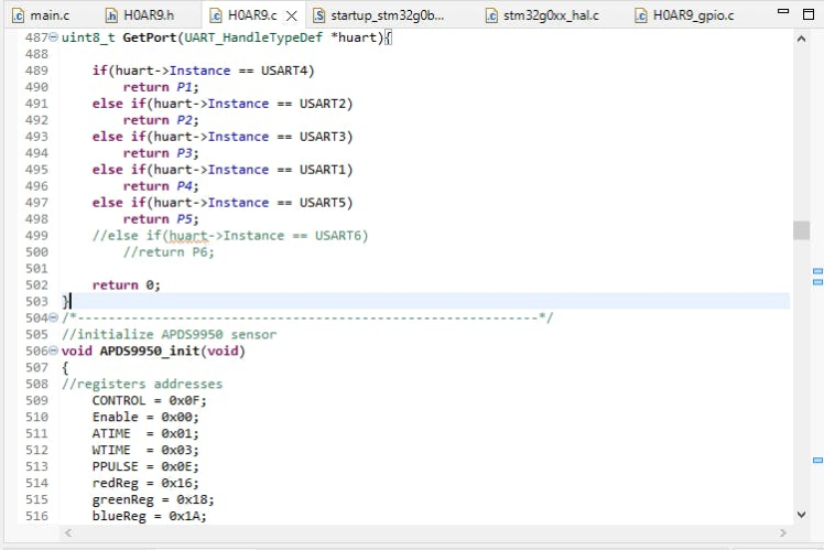
H0AR9x Firmware H0AR9.c code:
Second, comment the MX_USART6_UART_Init() port inside the Module_Peripheral_Init() function in the.c file, also commenting this port inside GetPort function.
H0AR9x Firmware H0AR9_gpio.c code:
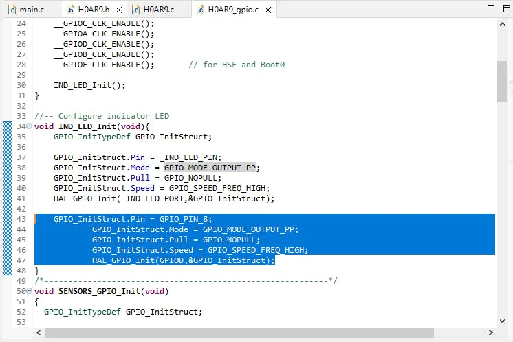
Third, add the instructions for configuring the pin you are going to use in H0AR9_gpio.c file.
GPIO_InitStruct.Pin = GPIO_PIN_8;
GPIO_InitStruct.Mode = GPIO_MODE_OUTPUT_PP;
GPIO_InitStruct.Pull = GPIO_NOPULL;
GPIO_InitStruct.Speed = GPIO_SPEED_FREQ_HIGH;
HAL_GPIO_Init(GPIOB,&GPIO_InitStruct);
H0AR9x Firmware main.c code:
First, we define the motion variable:
uint16_t prox;and then defined the other variable used in the code.
int q;And in the repeated closed loop, we made sure that MCU periodically checks the prox value of the sensor using the API from module factsheet.
SampleDistance(&prox);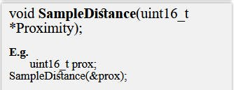
And if the motion achieves the required condition (i.e. if we wave in front of the PIR motion sensor), the servo motor is turned on at certain angles to move the robot's arms.
if (q > 15)
		HAL_GPIO_WritePin(GPIOB, GPIO_PIN_8, GPIO_PIN_SET);
		Delay_ms(1.5);
		HAL_GPIO_WritePin(GPIOB, GPIO_PIN_8, GPIO_PIN_RESET);
		Delay_ms(20);
                HAL_GPIO_WritePin(GPIOB, GPIO_PIN_8, GPIO_PIN_SET);
                Delay_ms(0.5);
		HAL_GPIO_WritePin(GPIOB, GPIO_PIN_8, GPIO_PIN_RESET);
		Delay_ms(10);
                HAL_GPIO_WritePin(GPIOB, GPIO_PIN_8, GPIO_PIN_SET);
                Delay_ms(2.5);
		HAL_GPIO_WritePin(GPIOB, GPIO_PIN_8, GPIO_PIN_RESET);
Delay_ms(50);- Check out this project for : How is a Servo Controlled.
Note: For this project, make sure you're using the standard 180° servo.
How is a Servo Controlled?

How is a Servo Controlled?
Step 3: Test the System ???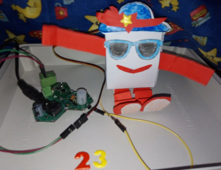
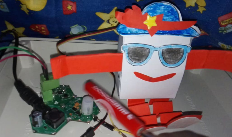
In conclusion, the DIY interactive paper robot with Hexabitz is an exciting project that combines art, technology, and education. It offers an engaging way for children to learn about robotics while having fun building their own unique robots. Let's dive into this project and unleash our creativity!
References:Code
Credits
Related products


Leave your feedback...