
Loopie - Diy Rgb Lamp

Made by CodersCafeTech / Displays / Home Automation / Lights
About the project
A minimalistic RGB LED Lamp
Project info
Difficulty: Easy
Platforms: Arduino, Digilent, Digispark
Estimated time: 5 hours
License: Apache License 2.0 (Apache-2.0)
Items used in this project

Hand tools and fabrication machines
Story
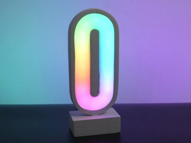
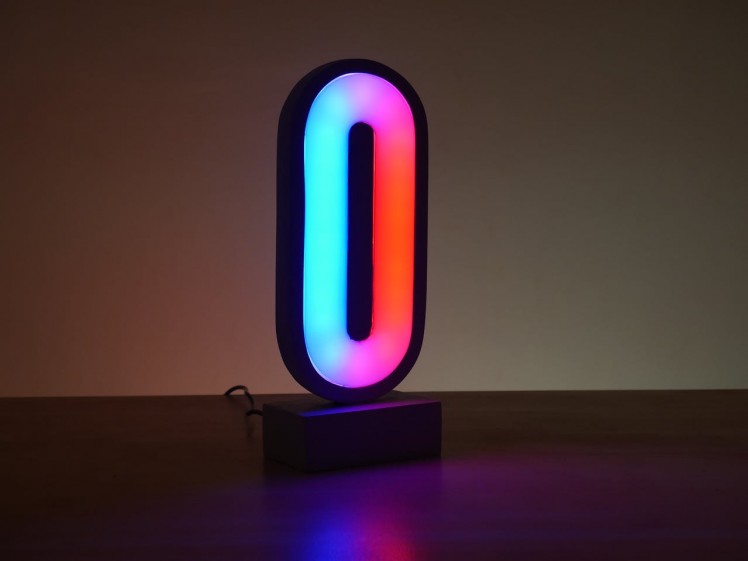
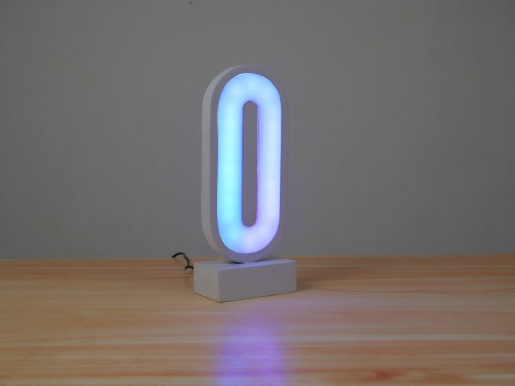
Meet Loopie, a minimalistic, enticing RGB LED lamp that can easily fit everywhere in your living space. The unique mystic shape of this lamp will make you lose all sense of time. In this video, we will be guiding you through the steps explaining how to build it on your own. It's very cheap and easy to replicate. Are you interested in doing it yourself? Let's get building.
Design
In this project, we've chosen a rounded rectangle shape that is not commonly used for LED lamps. But Why?
Let's learn some psychology. There are many interesting facts to consider when working with different shapes in design. It takes less cognitive brainpower to see rounded rectangles than it does to register sharp-cornered ones. This means it takes the visual senses more time to register the points of a rectangle than with an ellipse of the same size. It seems that a shape with sharp corners interrupts thought by forcing the brain to pause at each point until they complete the circuit.
The first and foremost meaning of rounded shape is eternity since they have no beginning or end. The circle has a long association with the sun and Earth as well as other cosmic objects while the ellipse is similar to the whole universe. That’s why round shapes may give the feeling of magic and mystery. In addition, unlike the shapes, rounded shapes don’t have angles so it makes them softer and milder.
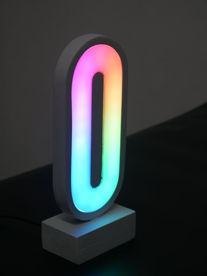
As a result, by choosing this rounded rectangle shape, Loopie can provide an eternal, magical, and pleasant feel to the viewers.


Electronic Components
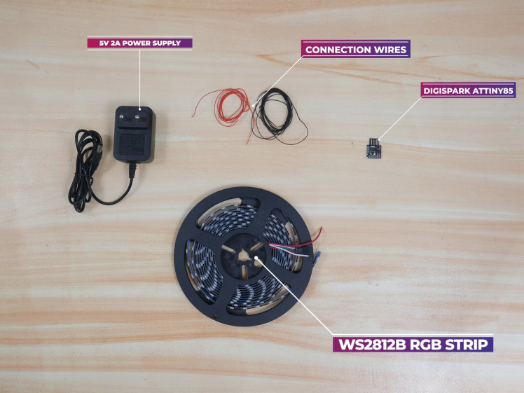
These are the major electronic components required for this project. Arduino is too big or too much for this project, so here we are going with the Digispark Attiny85 as the MCU. It is similar to the Arduino line mostly in regarding the programming way, it is cheaper, smaller, and quite powerful. It is an MCU based on ATtiny85.

Just as most Arduino boards come with a USB port for programming and sometimes as a source of power, Digispark comes with an onboard USB connector that can be plugged directly into a computer for programming of the device. The board can be powered via the USB port which will feed 5V to the board or from an external source via its VIN pin that can accept ~7 to 35V which will be regulated down to 5V through an onboard 78M05 voltage regulator.
If you are using more than 100 LEDs use any other powerful MCU
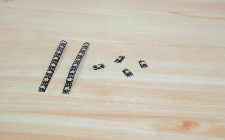
For lighting up this project, we are using WS2812B 5V Addressable RGB LED Strip is extremely flexible, easy to use and each LED of the strip can be controlled separately by using a microcontroller. Each LED has been equipped with an integrated driver that allows you to control the color and brightness of each LED independently.

The LED strip should be powered using a 5V power source, and Digispark will also work in 5V. Our device needs around 30 Led's, so we need at least 1.5 A current for the power supply. 5V 2A AC to DC adapter will do the job.
We also used some thin silicone wires for making connections.
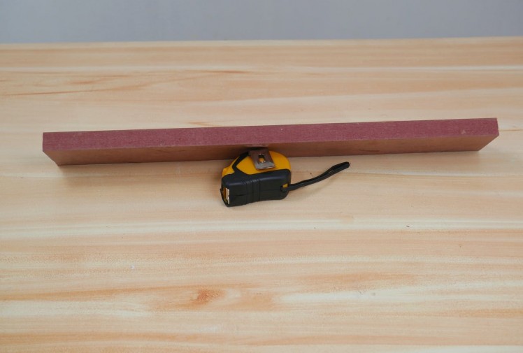
For this project, we are using leftover MDF pieces from the earlier project. The proper diffusion is possible even if there is a considerable distance between the acrylic and the MDF board. That's why we used this wood, with this much thickness.

Testing
For uploading the code from Arduino IDE to Digispark Attiny85, just follow the instructions here.

Then we uploaded our code to the MCU. You can grab the code from here.
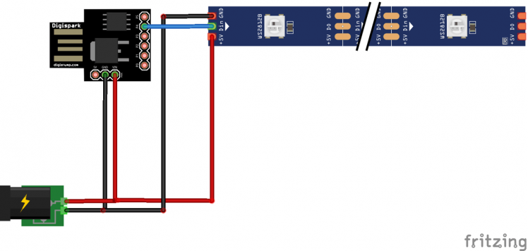
After, we connected the components as per the schematics and powered it up.
The Led is working flawlessly. The library here used is Adafruit Neopixel. You can read more about it here.
Now let's move on to the woodworking part.
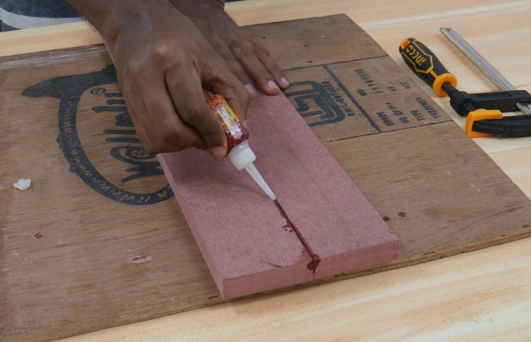
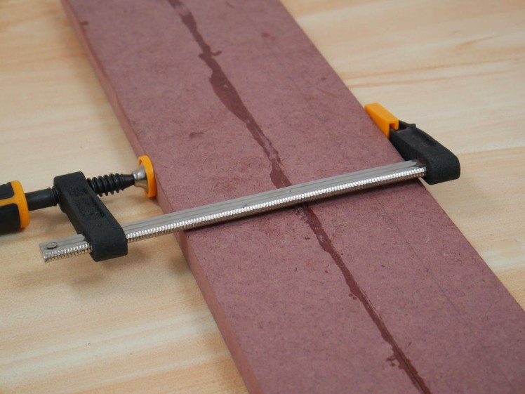
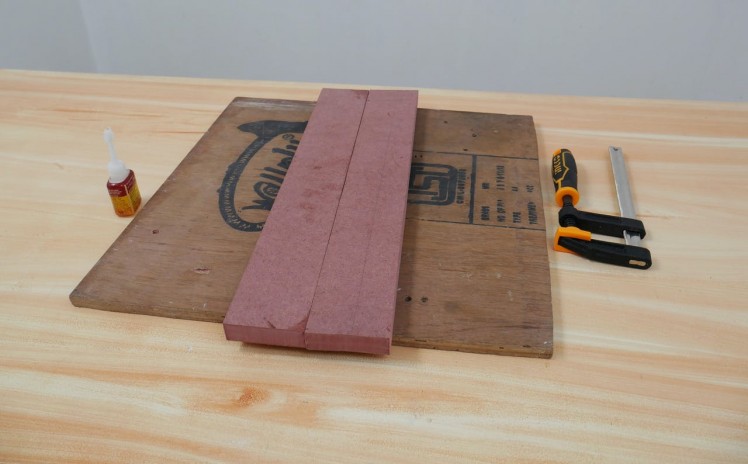
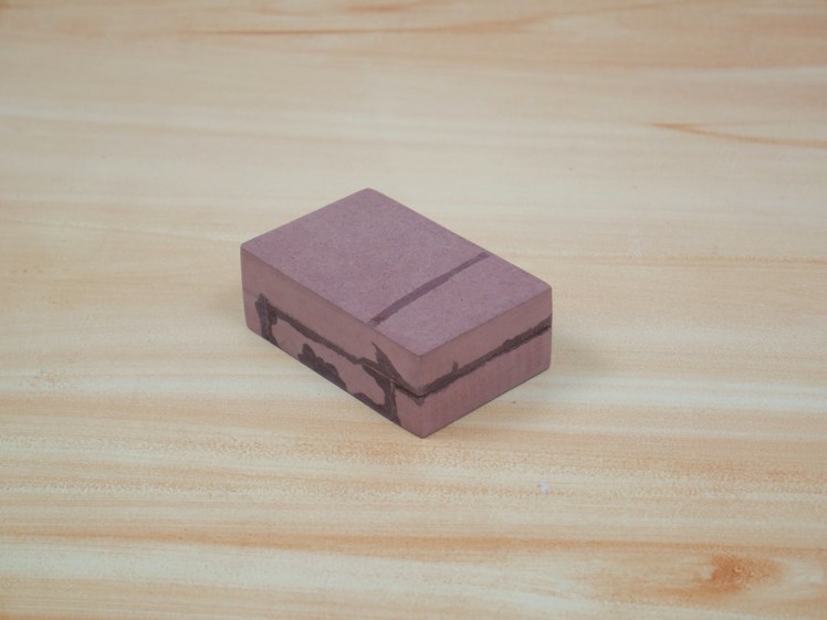
Edge to Edge Gluing
So we can join these two MDF boards to get the required length for the project, using instant glue. Then we used an F clamp for creating more inward pressure. After reaching the final strength we removed the clamp and sanded off the glue remnants to make the board smooth.
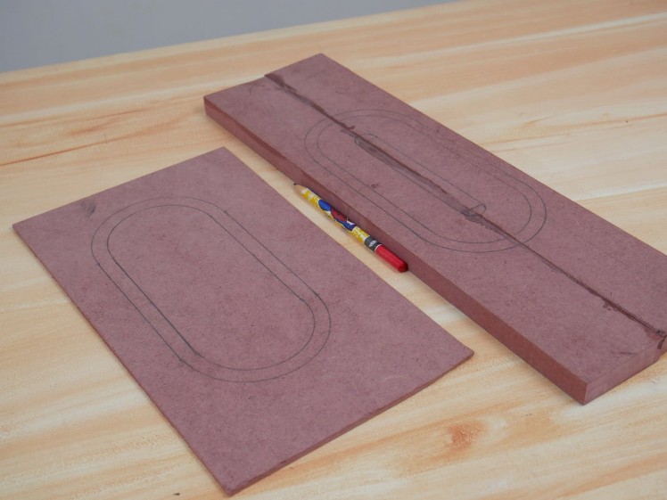
Cutting
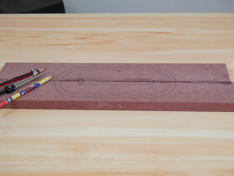
We outlined the shape on the wood with a pencil, compass, and ruler. This would help us to stay on track with our cutting, and minimize chances for errors.
Then we started cutting with a jigsaw. For the inside cut, we drilled small holes for getting the job done.
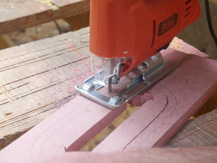
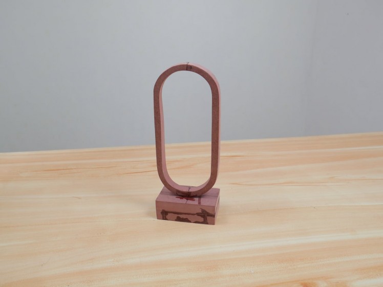
Finally, we have our wood pieces. The cut is not that accurate, we will adjust it according to the diffusion panels.
If you need accurate cuts, please go with the CNC router.
Laser Cut
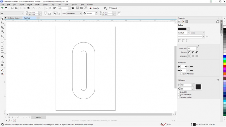
As the diffusing channel, we have used a 2mm white acrylic sheet. We designed an SVG file in Corel draw according to the measurements.
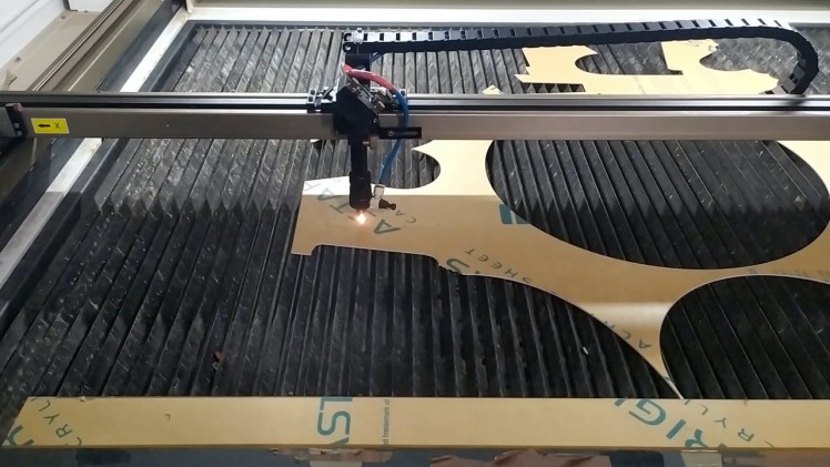
Then we laser cut the material in a laser cutting shop by giving the SVG file to them. It seems to be super easy.
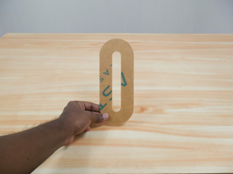
After we sanded the wooden pieces according to this diffusing panel for making it tight fit.
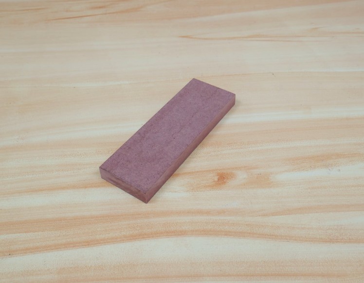
Making the Stand
So we can make stand for this led from this piece of wood. The stand has to be of considerable length when compared with the upper portion, so we took around 10 cm for the stand as the length and 4cm as the breadth.
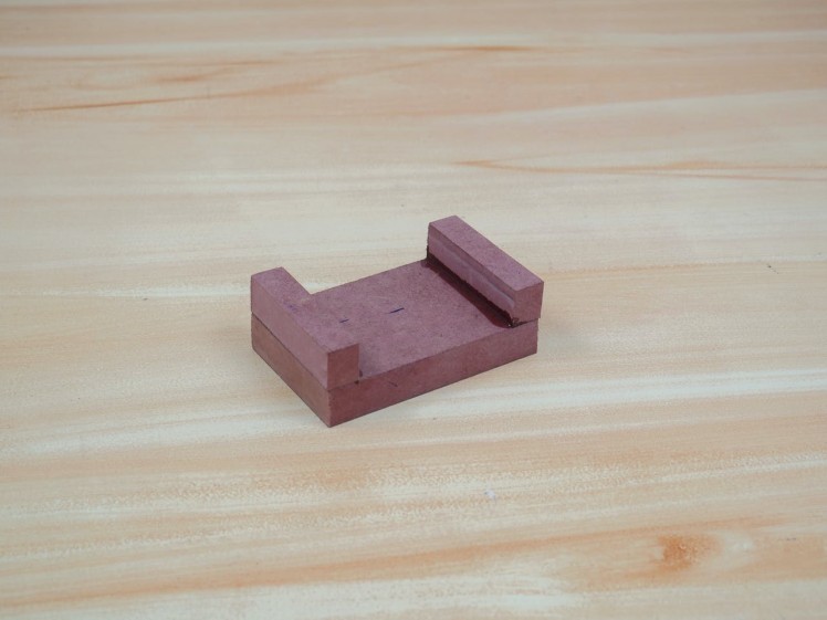
All the components can be fitted into this area. We also made a hole in the stand for letting the power cable in.
Painting
Before painting, we assembled the top portion with the stand using some instant glue.
Then we drilled a hole connecting the top layer and stand, to draw led connections.
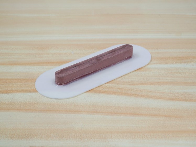
After that, we glued the center portion with acrylic.
We sanded the whole wood using 80, 120, 180 and 220 grits sandpaper to make it very smooth.
First, we primed the wood surfaces with normal wood primer, for the center we have used some masking tape to avoid the dripping of paint to the acrylic.
We actually need a grey variant for the device, but we have only white and black paints, so added a little bit of black to the white for getting the grey variant.
Securing Components
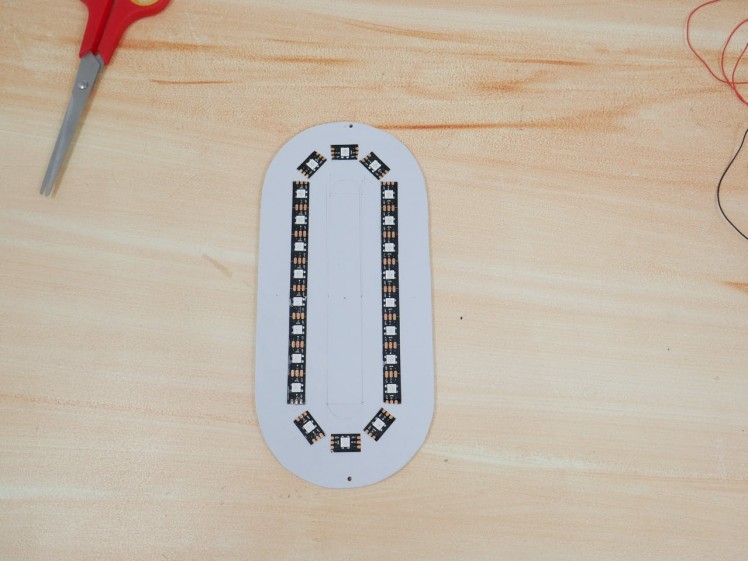
First, we secured the led strip by cutting it to the required length on the bottom layer. So we can pass these wires to the hole that we made on purpose.
1 / 3
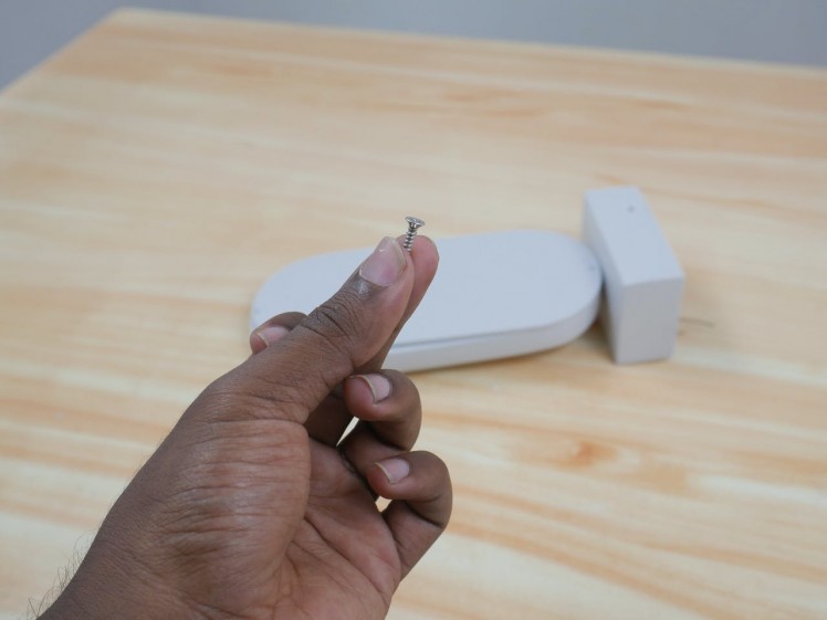
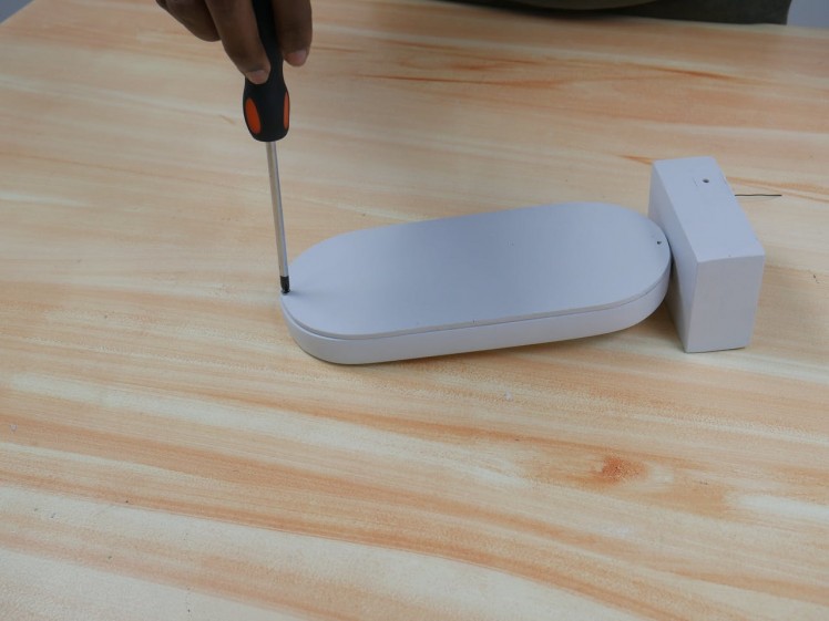
We fixed the top layer in the base layer using self Tapping head screws.
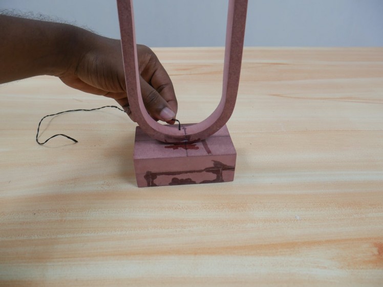
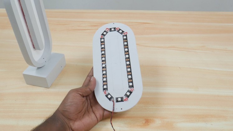
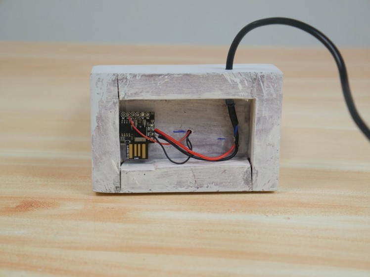
Then we passed the power cable in, through the hole made in the stand. After we soldered all the connections to the microcontroller as per the schematics. We used some wiring sleeves to avoid a short circuit for the power supply. You should be aware of that.
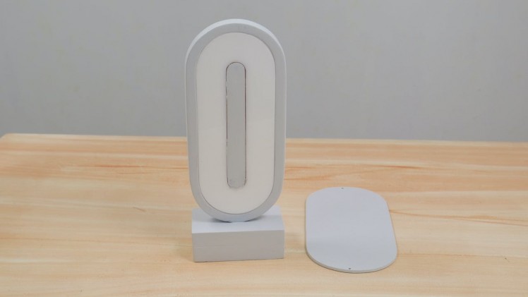
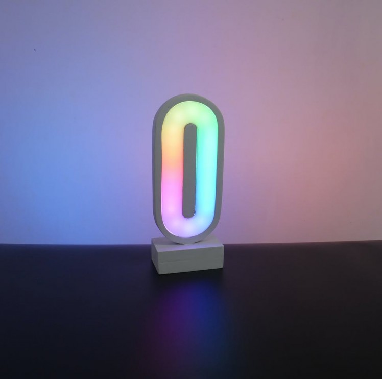
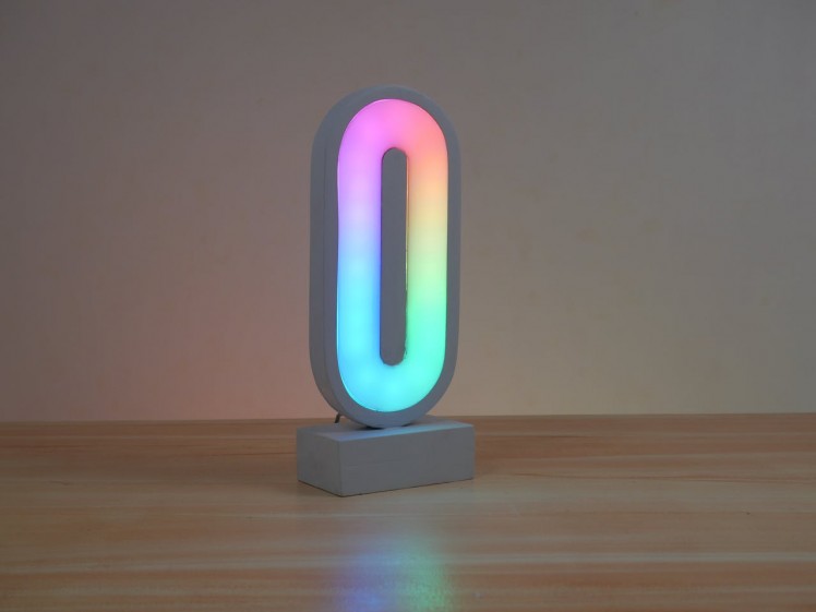
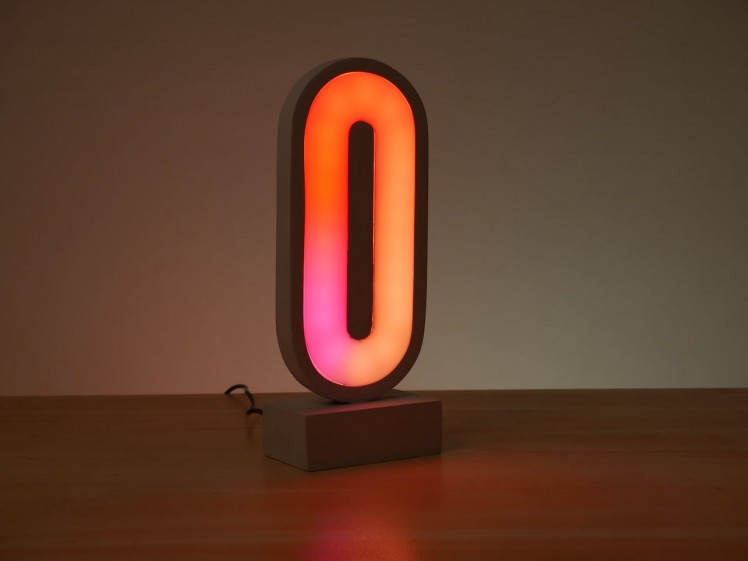
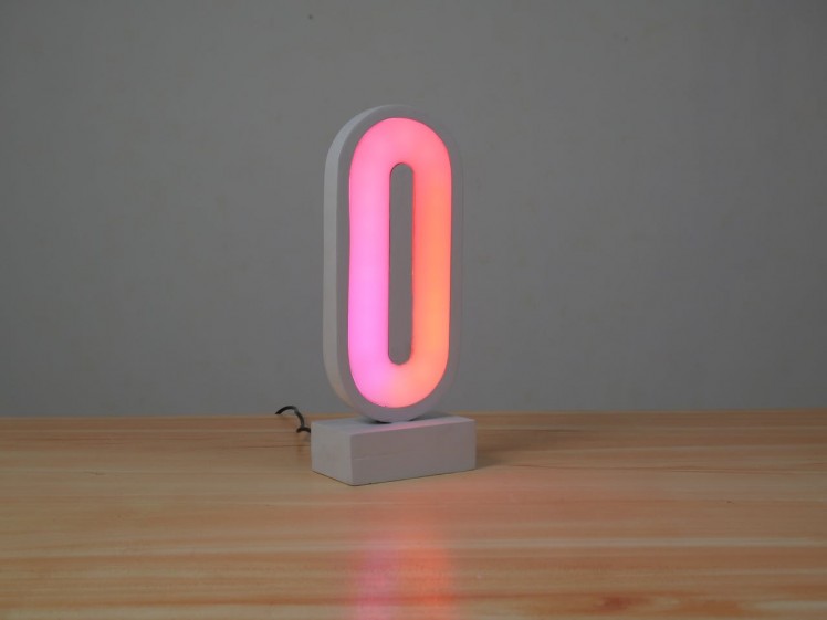
End Results!
Schematics, diagrams and documents
CAD, enclosures and custom parts
Code
Credits
Related products


Leave your feedback...