
Led Matrix Animated Time,date,temp And Humidity

Made by Ron / Environmental Sensing / Home Automation / Sensors / Weather
About the project
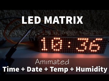
In this Tutorial we will learn how to use the LED Matrix MAX7219, to Display Current Temperature, Humidity, Time and Date.
Project info
Difficulty: Moderate
Estimated time: 1 hour
License: GNU General Public License, version 3 or later (GPL3+)
Items used in this project
Hardware components

Story
In this Tutorial we will learn how to use the LED Matrix MAX7219, Temperature and Humidity Sensor DHT11 and RTC DS1307 module to Display Current Temperature, Humidity, Time and Date.
Watch the Video!
Step 1: What You Will Need
1 / 6
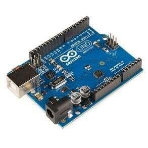


- Arduino UNO (or any other Arduino)
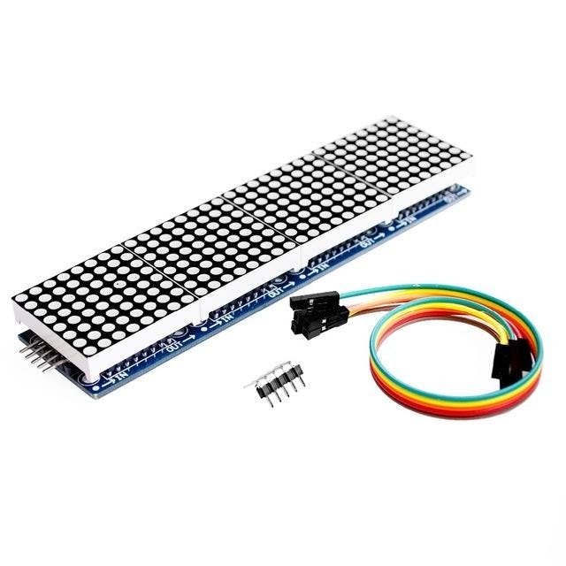
- LED MATRIX. We are going to use the FC-16 module which has four casacaded 8×8 LED Matrix Displays and a built-in MAX7219 LED Driver for each display.
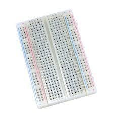
- Breadboard
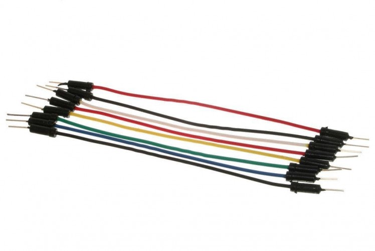
- Jumper wires
- RTC DS1307 module
- DHT11 sensor
- Visuino program: Download Visuino
Step 2: The Circuit
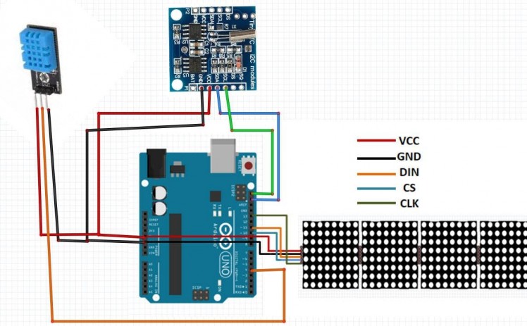
- Connect RTC DS1307 module pin[VCC] to Arduino pin[5V]
- Connect RTC DS1307 module pin[GND] to Arduino pin[GND]
- Connect RTC DS1307 module pin[SDA] to Arduino pin[SDA]
- Connect RTC DS1307 module pin[SCL] to Arduino pin[SCL]
- Connect DHT11 sensor pin[GND] to Arduino pin[GND]
- Connect DHT11 sensor pin[VCC] to Arduino pin[5V]
- Connect DHT11 sensor signal pin[S] to Arduino digital pin[4]
- Connect LED Matrix pin[VCC] to Arduino pin[5V]
- Connect LED Matrix pin[GND] to Arduino pin[GND]
- Connect LED Matrix pin[DIN] to Arduino digital pin[11]
- Connect LED Matrix pin[CS] to Arduino digital pin[10]
- Connect LED Matrix pin[CLK] to Arduino digital pin[13]
Note: Read also the part for Troubleshooting below
Step 3: Start Visuino, and Select the Arduino UNO Board Type
1 / 2
The Visuino: https://www.visuino.eu also needs to be installed. Download Free version or register for a Free Trial.
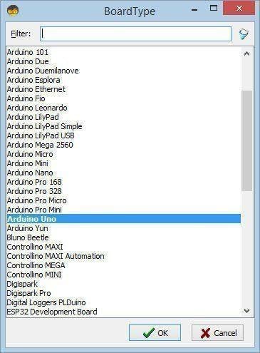
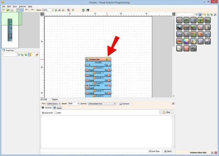
Start Visuino as shown in the first picture Click on the "Tools" button on the Arduino component (Picture 1) in Visuino When the dialog appears, select "Arduino UNO" as shown on Picture 2
Step 4: In Visuino Add Components
1 / 13

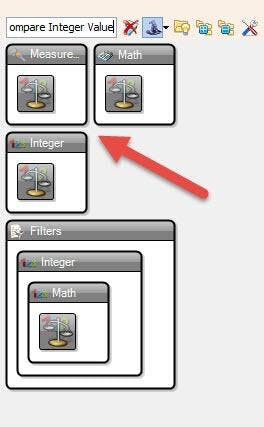
- Add 2X "Compare Integer Value" component
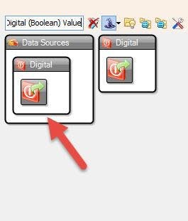
- Add 2X "Digital (Boolean) Value" component
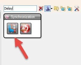
- Add "Delay" component
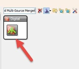
- Add "Digital Multi-Source Merger" component
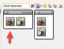
- Add "Clock Generator" component
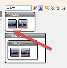
- Add 2X "Counter" component
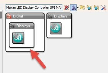
- Add "Maxim LED Display Controller SPI MAX7219/MAX7221" component
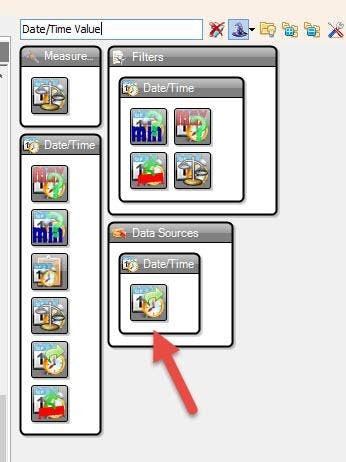
- Add "Date/Time Value" component
- Add "Real Time Clock(RTC) DS1307" component
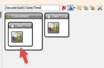
- Add "Decode(Split) Date/Time" component
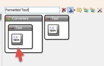
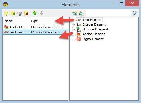
- Add 4X "Formatted Text" component
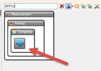
- Add "DHT11" component
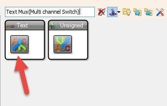
- Add "Text Mux(Multi channel Switch)" component
- Add "Integer Multi Source" component
Step 5: In Visuino Set Components
1 / 15

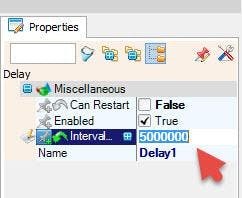
- Select "Delay1" and in the properties window set "Interval (uS)" to 5000000
- Select "DigitalValue2" and in the properties window set "Value" to True
- Select "ClockGenerator1" and in the properties window set "Frequency" to 10 and Select "Enabled" and click on the Pin Icon and select "Boolean SinkPin"
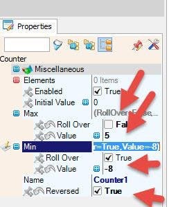
- Select "Counter1" and in the properties window set Max>Roll Over to False and Max>Value to 5
- Select "Counter1" and in the properties window set Min>Value to -8
- Select "Counter1" and in the properties window set "Reversed" to True
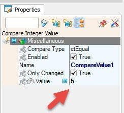
- Select "CompareValue1" and in the properties window set "Value" to 5
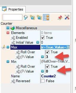
- Select "Counter2" and in the properties window set Max>Value to 3
- Select "Counter2" and in the properties window set Min>Value to 0
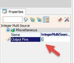
- Select "IntegerMultiSource1" and in the properties window set to Output Pins to 3
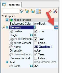
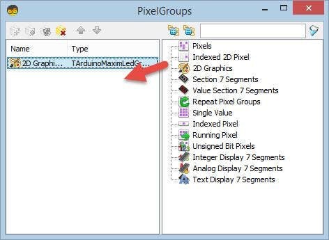
- Double click on the "LedController1" and in the "Pixel Groups" window drag "2D Graphics" to the left side
- and in the properties window set "Mirror Horizontal" to True and "Reverse Horizontal" to True and set "Width" to 32
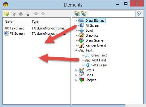
- also select "Elements" in the properties window and click on the 3 dots button
In the Elements window drag:
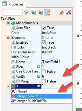
- "Text Field" to the left side and in the properties window set "Wrap" to False, and click on the "X" pin button and select "Integer Sink Pin" and click on the "Y" pin button and select "Integer Sink Pin"
- "Fill Screen" to the left side
Close the "Elements" Window
Close the "Pixel Groups" window
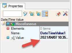
- Select "DateTimeValue1" and in the properties window set "Value" to your current date and time
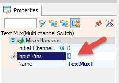
- Select "TextMux1" and in the properties window set "Input Pins" to 4
- Select "FormattedText1" and in the properties window set "Text" to %0%1
- Double click on the "FormattedText1" and in the Elements Window
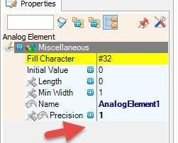
- drag "Analog Element" to the left side and in the properties window set "Precision" to 1
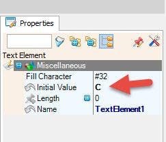
- drag "Text Element" to the left side and in the properties window set "Initial Value" to C
Close the Elements Window
- Select "FormattedText2" and in the properties window set "Text" to %0%1
- Double click on the "FormattedText2" and in the Elements Window
- drag "Analog Element" to the left side and in the properties window set "Precision" to 0
- drag "Text Element" to the left side and in the properties window set "Initial Value" to %
Close the Elements Window
- Select "FormattedText3" and in the properties window set "Text" to %0:%1
- Double click on the "FormattedText3" and in the Elements Window
- drag 2X "Text Element" to the left side
Close the Elements Window
- Select "FormattedText4" and in the properties window set "Text" to %0.%1
- Double click on the "FormattedText4" and in the Elements Window
- drag 2X "Text Element" to the left side
Close the Elements Window
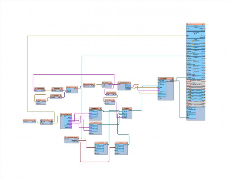
Step 6: In Visuino Connect Components
1 / 5

- Connect "DateTimeValue1" pin Out to "RealTimeClock1" pin Set
- Connect "RealTimeClock1' pin Control I2C to Arduino pin I2C In
- Connect "RealTimeClock1' pin Out to "DecodeDateTime1" pin In
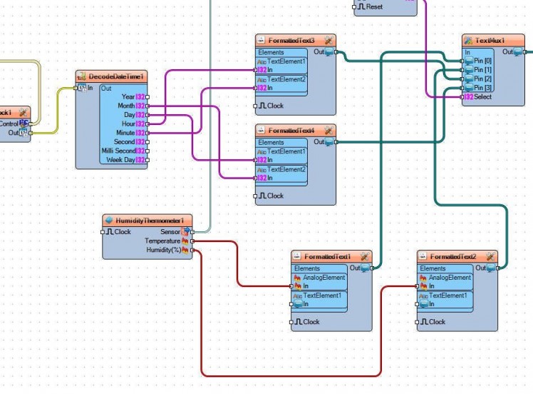
- Connect "DecodeDateTime1" pin "Month" to "FormattedText4 > "TextElement2" pin In
- Connect "DecodeDateTime1" pin "Day" to "FormattedText4 > "TextElement1" pin In
- Connect "DecodeDateTime1" pin "Hour" to "FormattedText3 > "TextElement1" pin In
- Connect "DecodeDateTime1" pin "Minute" to "FormattedText3 > "TextElement2" pin In
- Connect "HumidityThermometer1" pin Sensor to Arduino Board Digital pin [4]
- Connect "HumidityThermometer1" pin Temperature to "FormattedText1>AnalogElement1" pin In
- Connect "HumidityThermometer1" pin Humidity to "FormattedText2>AnalogElement1" pin In
- Connect "FormattedText1" pin Out to "TextMux1" Pin[0]
- Connect "FormattedText2" pin Out to "TextMux1" Pin[1]
- Connect "FormattedText3" pin Out to "TextMux1" Pin[2]
- Connect "FormattedText4" pin Out to "TextMux1" Pin[3]
- Connect "TextMux1" Pin Out to "LedController1 > Text Field" Pin In
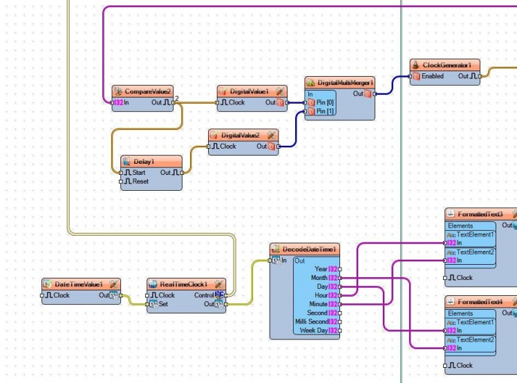
- Connect "CompareValue2" Pin Out to "Delay1" Pin "Start" and "DigitalValue1" Pin Clock
- Connect "Delay1" Pin Out to "DigitalValue2" Pin Clock
- Connect "DigitalValue1" Pin Out to "DigitalMultiMerger1" Pin [0]
- Connect "DigitalValue2" Pin Out to "DigitalMultiMerger1" Pin [1]
- Connect "DigitalMultiMerger1" pin Out to "ClockGenerator1" Pin "Enabled"
- Connect "ClockGenerator1" pin Clock to "Counter1" Pin In
- Connect "Counter1" pin Out to "IntegerMultiSource1" pin In, and "CompareValue1" pin In and "CompareValue2" pin In
- Connect "CompareValue1" pin Out to "Counter2" Pin In
- Connect "Counter2" pin Out to "TextMux1" pin Select
- Connect "IntegerMultiSource1" pin [0] to "LedController1 > Text Field" Pin Y
- Connect "IntegerMultiSource1" pin [1] to "LedController1 > Fill Screen" Pin Clock
- Connect "IntegerMultiSource1" pin [2] to "LedController1 > Text Field" Pin Clock
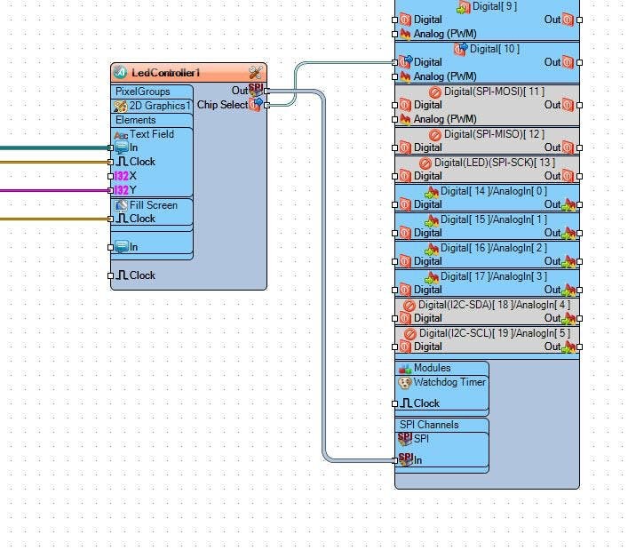
- Connect "LedController1" Pin Out SPI to Arduino Board pin SPI In
- Connect "LedController1" Pin Chip Select to Arduino Board Digital pin [10]
Step 7: Generate, Compile, and Upload the Arduino Code
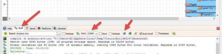
In Visuino, at the bottom click on the "Build" Tab, make sure the correct port is selected, then click on the "Compile/Build and Upload" button.
Step 8: Play
If you power the Arduino UNO module, the LED Matrix will start to Display the temperature,humidity,time and date from bottom side to the top side.
Congratulations! You have completed your project with Visuino. Also attached is the Visuino project file, that I created for this tutorial, you can download it and open it in Visuino: https://www.visuino.eu
Step 9: Troubleshooting
In my case When powering the Arduino the LED Matrix was blinking and the Text was not fully displayed. The reason for this was because MAX7219 chip is very sensitive to any voltage interference.
To solve that I added a 47uf electrolytic capacitor between the LED Matrix VCC(+) and GND(-), make sure you connect the capacitor right, + on (VCC) and - on the (GND)
Schematics, diagrams and documents
Code
Credits
Related products


Leave your feedback...