
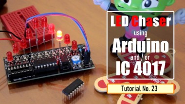
Led Chaser Circuits Using Ic4017 And Arduino

Made by tarantula3 / 3D Printing / Displays / Kids & Family / Lights / IoT
About the project
In this tutorial I am going to create 3 chaser circuits using Arduino and IC4017 decade counter.
Project info
Difficulty: Easy
Platforms: Arduino, circuito.io, VoCore, PCBWay
Estimated time: 1 hour
License: GNU General Public License, version 3 or later (GPL3+)
Items used in this project
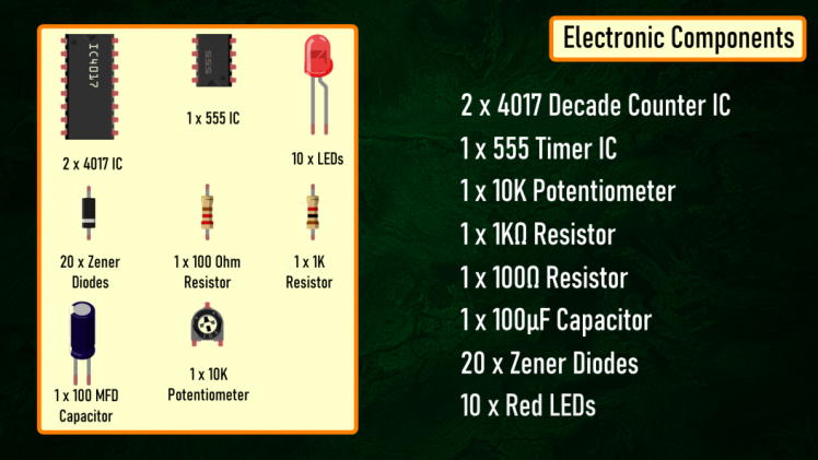
Hardware components

|
4017 Decade Counter IC | x 2 | |
|
|
555 Timer IC | x 1 | |
|
|
10 K Potentiometer | x 1 | |
|
|
1 Kilo Ohm Resistor | x 1 | |
|
|
100 Ohm Resistor | x 1 | |
|
|
100 MFD Capacitor | x 1 | |
|
|
Zener Diodes | x 20 | |
|
|
Red LEDs | x 10 | |
|
Arduino Nano V3 | x 1 |
View all
Story
A Chaser Circuit consists of a clocked IC or other electronic unit like an Arduino that drives an array of LEDs in such a way that individual LEDs (or small groups of LEDs) turn on and off in a predetermined and repeating sequence, thus producing a visually attractive display in which one or more ripples of light seem to repeatedly run through a chain or around a ring of LEDs.
In this tutorial I am going to create 3 chaser circuits using Arduino and IC4017 decade counter.https://youtu.be/F6V1AjESWbU
Using IC555 and IC4017
Lets first create the chaser circuit using the IC4017 decade counter and IC555 timer IC.
Components Required
 For the Non-Arduino bit we need:
- 2 x 4017 Decade Counter IC
- 1 x 555 Timer IC
- 1 x 10 K Potentiometer
- 1 x 1 Kilo Ohm Resistor
- 1 x 100 Ohm Resistor
- 1 x 100 MFD Capacitor
- 20 x Zener Diodes and
- 10 x Red LEDs
Circuit Diagram
1. Forward Chaser
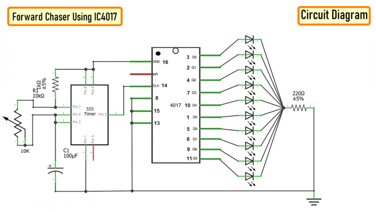 The circuit is very simple. The 555 Timer IC operates as a clock oscillator or clock generator. The output on PIN-3 goes high causing a shift. The signal from the 555 IC clocks the 4017 decade counter. Output of 555 timer IC on PIN-3 is given as an input to 4017 IC through PIN-14. Whenever a pulse is received at the input of IC 4017, the counter increments the count and activates the corresponding output PIN. This IC can count upto 10, so we have attached 10 LEDs to the circuit. By increasing or decreasing the value of resistance of the 10K pot we can adjust the speed of the chaser circuit. Since only one LED will be turned on at a given time, I have attached just one 220ohm current limiting resistor to the cluster of LEDs. Demo: So this is how it looks like.
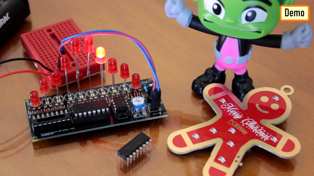
2. Forward Reverse Chaser using 2 x IC4017
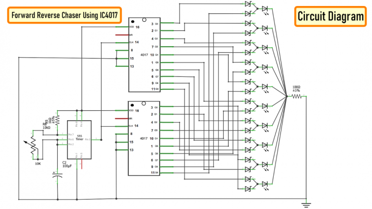 Now, to give the forward and reverse effect we are attaching another 4017 IC to this circuit. If lets say the 1st IC connects from 1 to 10 (left to right) then the second one should connect from 10 to 1 (right to left). However, now we cannot connect the counter ICs directly to the LEDs as we did before. We have to use Diodes to stop the reverse flow of current to the 2nd IC. We have also lowered the value of the current limiting resistor to 100ohms as at a given time 2 LEDs will be on, one running from left and one from the right hand side. Demo: Now lets do a quick test. By lowering the speed I can get the desired forward and reverse effect. By removing one of the 4017 ICs we can get the effect that I demonstrated in the previous example.
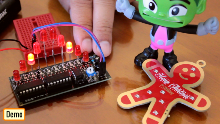
3. Forward Reverse Chaser using 1 x IC4017
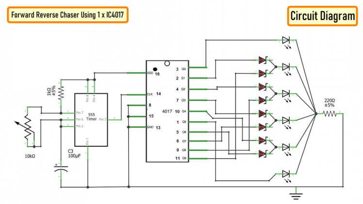 To get a forward reverse effect using one 4017 IC we need to connect 8 diodes to the circuit. The 1st and the 6th LED will be directly connected to the IC4017. The LEDs at the far end will get signals from only one pin however the one in the middle will receive signals from 2 x pins and hence we need diodes to stop the reverse flow of the current. Demo: So this is how it looks like.
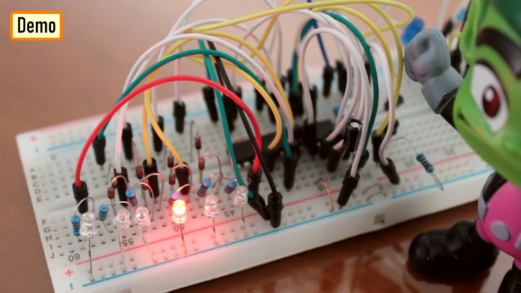
Using Arduino
Now, I am going to repeat the same setup using an Arduino.
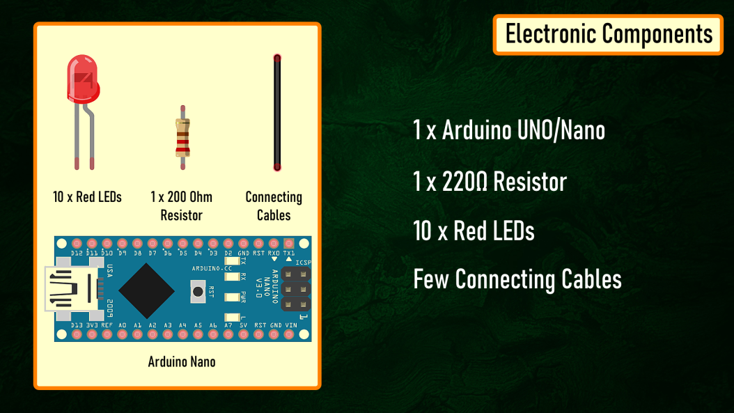
Components Required

- 1 x Arduino Uno/Nano (whatever is handy)
- 1 x 220 Ohm Resistor
- 10 x Red LEDs
- Few Connecting Cables
The beauty of using an Arduino is that the setup remains the same for all the previously shown circuits, the only thing that changes is the code. So, I am going to use this simple setup for the rest of the tutorial.
Circuit Diagram
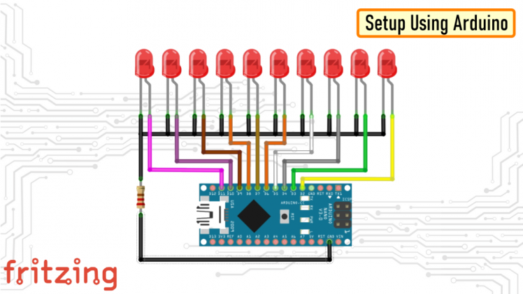
1. Forward Chaser
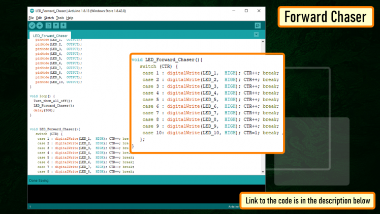 Code: The code for the forward chaser is very simple. Start by defining the constants and the global variables that will be used throughout the code. Then in the setup section define the pin modes. Now, in the loop section we are going to start by turning off all the LEDs followed by turning one LED on at a time. A counter is used to tell the loop which LED to turn on in the next cycle. Once the value of the counter reaches 10 (the maximum number of LEDs) the counter resets to 1 and the 1st LED lights up and the cycle continues. Demo: So this is how it looks like.
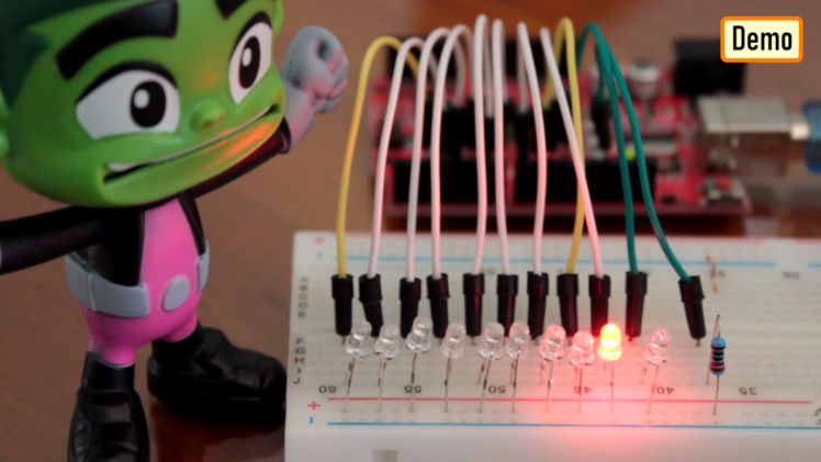
2. Forward Reverse Chaser
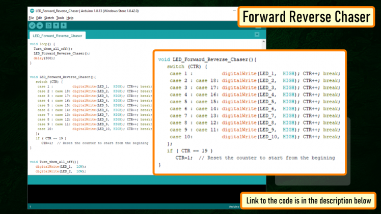 Code: The code is same as the previous setup. The only thing that changes is the function that deals with the LEDs. In this setup we cycle through LED 1 to LED 10 and then reverse from LED 9 to LED 1. The counter resets when the max count is reached.
Demo: So this is how it looks like.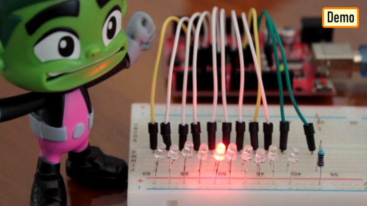
3. Left-Right Chaser
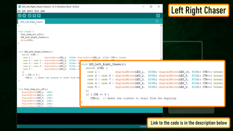 Code: The setup is exactly the same as the previous two setups. This function is the one which turns on the LEDs at the two far ends and then the one before that and likewise until they cross each other. The counter is reset when the max count is reached.
Demo: So this is how it looks like.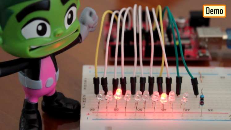
PCF8574 8-bit GPIO Port Extender

To know more about this IC please check out my tutorial number 10 : "PCF8574 GPIO Extender - With Arduino and NodeMCU".Thanks
Full Blog Post: https://diy-projects4u.blogspot.com/2021/01/led-chaser-circuits-using-ic4017-and.htmlVideo: https://youtu.be/F6V1AjESWbUGerber File: 1. https://drive.google.com/file/d/108EUNylmearJgU_4qSlxNr9GAPGrLGRh/view?usp=sharingCode: 1. Forward: https://drive.google.com/file/d/1bw1la5oRMWZRXsfYJ41qNbCoEkJsZHBM/view?usp=sharing 2. Forward Reverse: https://drive.google.com/file/d/1Oag8kxbvfxZg7StFrYzWwtcqQx6okwzd/view?usp=sharing 3. Left Right: https://drive.google.com/file/d/17ZEsKU3OFrcjaJpvyUJMQbHQ-lznbp0H/view?usp=sharingSketch: 1. With Arduino: https://drive.google.com/file/d/1YHWvpkDbGbGVHwX65HwvwS3_JyFwZdK9/view?usp=sharing 2. Without Arduino: https://drive.google.com/file/d/1LdxcS1BXf3GtQTRhWCoCZKm6ppRwsc5k/view?usp=sharing
- BTC: 1M1PdxVxSTPLoMK91XnvEPksVuAa4J4dDp
- DOGE: DDe7Fws24zf7acZevoT8uERnmisiHwR5st
- LTC: LedWPdTaUzr5iaJx8garkcykSs1DZU1FAx
- ETH: 0xB62a901Ee6cE24f3153CA6ae565C2A6533066faA
- BAT: 0xB62a901Ee6cE24f3153CA6ae565C2A6533066faA
- BCH: 14xJhpswSAQi375S39yDFsrBFtDoiLVX1J
Credits
Related products


Leave your feedback...