
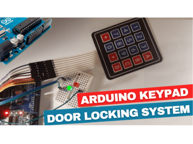
Keypad Controlled Door Locking System Using Arduino

Made by Ron / Communication / Home Automation / Security / Sensors
About the project
In this tutorial we will learn how to make a Locking system using a Keypad and Arduino.
Items used in this project
Hardware components

|
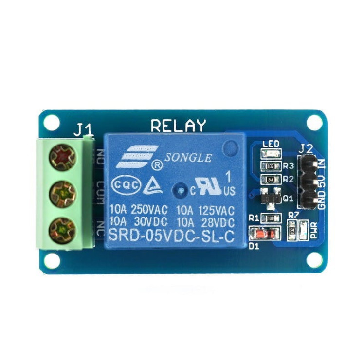
DFRobot Gravity: Digital 5A Relay Module | x 1 | |
|
|
Arduino UNO | x 1 | |
|
|
Jumper wires (generic) | x 1 | |
|
|
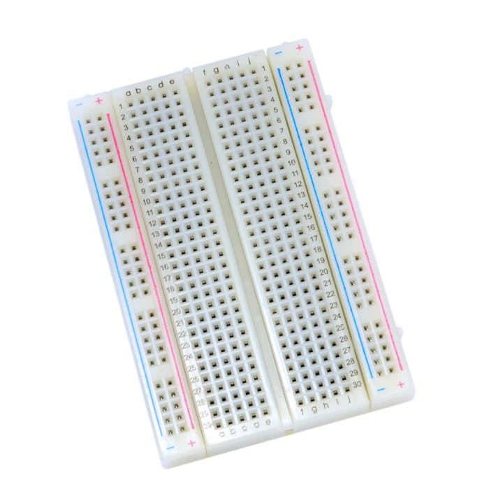
Breadboard (generic) | x 1 | |
|
|
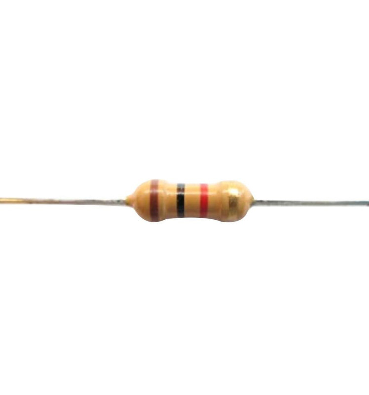
Resistor 1k ohm | x 2 | |
|
|
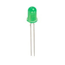
5 mm LED: Green | x 1 | |
|
|
LED (generic) | x 1 | |
|
|
Keypad | x 1 |
View all
Story
In this tutorial we will learn how to make a Locking system using a Keypad and Arduino. If you type the correct Code within a time limit of 5 seconds the door will open in our case the Green LED will glow. After the 5 seconds the it will lock back in our case the Red LED will glow.
To develop this project further you can easily connect a Relay with a Lock connected to it (See the schematic below).
Watch the Video!
Also checkout this tutorial: Arduino Nano Matrix Keypad With Visuino
Step 1: What You Will Need1 / 9

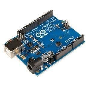
- Arduino UNO (Or any other Arduino)
- Keypad
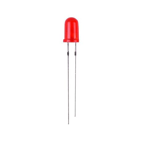
- 2X LED (Red & Green)
- 2X 1K ohm Resistor
- Jumper wires
- Breadboard
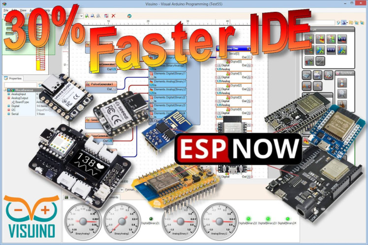
- Visuino program: Download Visuino
- Optional: A Relay

Thank you PCBWay for supporting this tutorial and helping users learn more about electronics.
What I like about the PCBWay is that you can get 10 boards for approximately $5 which is really cost effective for professional made boards, not to mention how much time you save!
Go check them out here. They also offer a lot of other stuff in case you might need it like assembly,3D printing,CNC machining and a lot more.
Step 3: The Circuit1 / 2
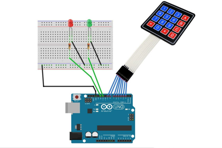
- Connect Keypad pin 1 to Arduino digital pin 2
- Connect Keypad pin 2 to Arduino digital pin 3
- Connect Keypad pin 3 to Arduino digital pin 4
- Connect Keypad pin 4 to Arduino digital pin 5
- Connect Keypad pin 5 to Arduino digital pin 6
- Connect Keypad pin 6 to Arduino digital pin 7
- Connect Keypad pin 7 to Arduino digital pin 8
- Connect Keypad pin 8 to Arduino digital pin 9
- Connect Arduino pin [GND] to breadboard pin GND Line
- Connect Arduino digital pin [11] to breadboard Resistor1
- Connect Arduino digital pin [12] to breadboard Resistor2
- Connect Resistor1 to Green LED positive pin [+]
- Connect Green LED negative pin [-] to breadboard pin GND Line
- Connect Resistor2 to Red LED positive pin [+]
- Connect Red LED negative pin [-] to breadboard pin GND Line
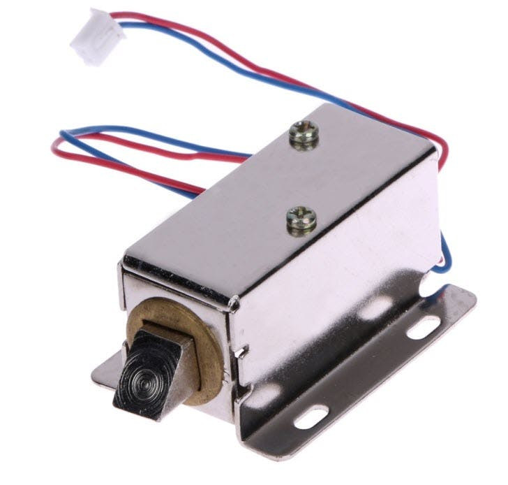
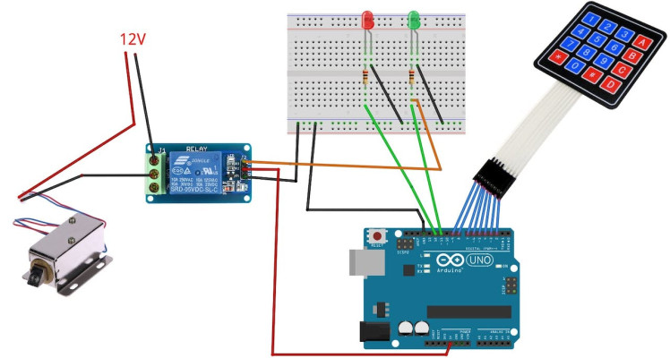
To Add a Relay and a solenoid:
- Connect Relay VCC pin(+) to Arduino 5V pin
- Connect Relay GND pin(-) to Arduino GND pin or to breadboard pin GND Line
- Connect Relay signal pin(S) to Arduino Digital pin 11
- Connect power supply 12V (+) to solenoid red wire(+)
- Connect power supply 12V (-) to solenoid pin(com)
- Connect solenoid black wire (-) to relay pin(NO)
1 / 2
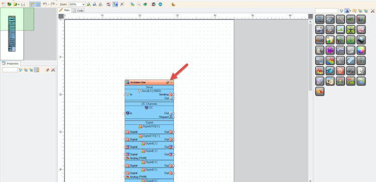
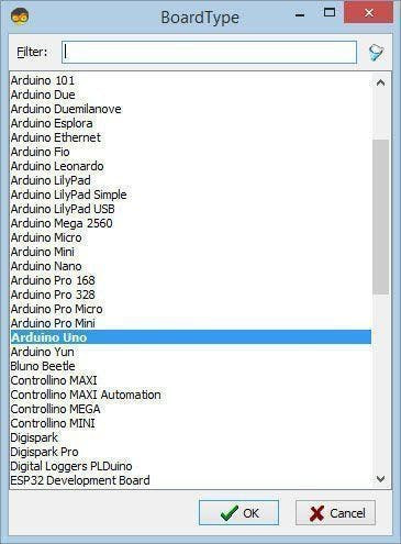
Start Visuino as shown in the first picture Click on the "Tools" button on the Arduino component (Picture 1) in Visuino When the dialog appears, select "Arduino UNO" as shown on Picture 2
Step 5: In Visuino Add Components1 / 5
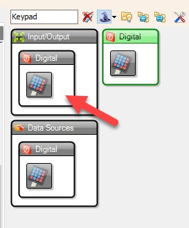
- Add "Keypad" component
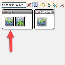
- Add "Char Multi Source" component
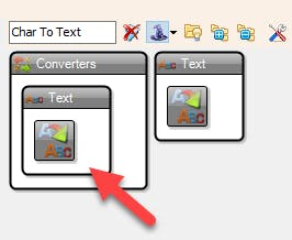
- Add "Char To Text" component
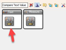
- Add "Compare Text Value" component
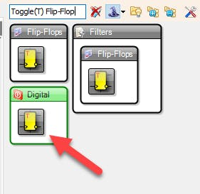
- Add "Toggle(T) Flip-Flop" component
- Add 2X "Delay" component
1 / 8
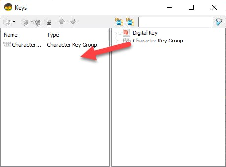
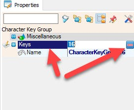
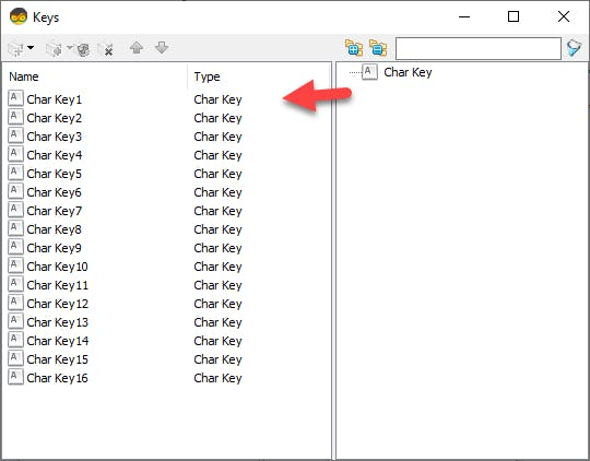


- Double click on the "Keypad1" and in the "Keys" window drag "Character Key Group" to the left side, in the properties window select "Keys" and click on the 3 dot button, now in a "Keys" window Drag 16X "Char Key" to the Left side, and for each key set "Character" in the properties window set "Character" for each in the order like you see on picture 6, for
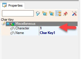
- "Char Key1" the "Character" will be 1
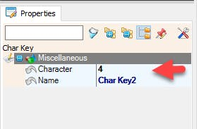
- for "Char Key2" the "Character" will be 4
- for "Char Key3" the "Character" will be 7
- for "Char Key4" the "Character" will be *
- for "Char Key5" the "Character" will be 2
- and so on until the end
- Close All the Windows
- Select "Delay1" and in the properties window set "Interval (uS)" to 5000000
- Select "Delay2" and in the properties window set "Interval (uS)" to 5000000
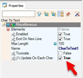
- Select "CharToText1" and in the properties window set "Update On Each Char" to True
To Set the Keypad Code: Select "CompareValue1" and in the properties window set the "Value" in this example it is 34571
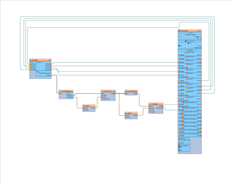
Step 7: In Visuino Connect Components1 / 3
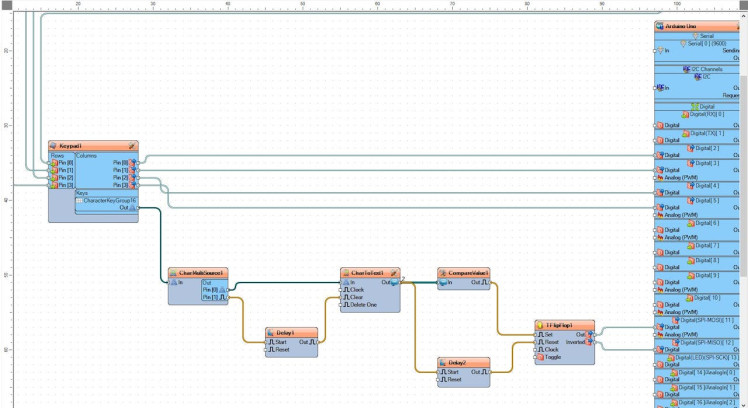
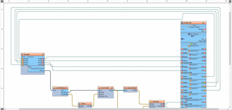
- Connect Arduino Digital Pin[6] to "Keypad1" > Rows Pin [0]
- Connect Arduino Digital Pin[7] to "Keypad1" > Rows Pin [1]
- Connect Arduino Digital Pin[8] to "Keypad1" > Rows Pin [2]
- Connect Arduino Digital Pin[9] to "Keypad1" > Rows Pin [3]
- Connect "Keypad1" > Columns Pin [0] to Arduino Digital Pin[2]
- Connect "Keypad1" > Columns Pin [1] to Arduino Digital Pin[3]
- Connect "Keypad1" > Columns Pin [2] to Arduino Digital Pin[4]
- Connect "Keypad1" > Columns Pin [3] to Arduino Digital Pin[5]
- Connect "Keypad1" > "CharacterKeyGroup16" pin [Out] to "CharMultiSource1" pin[In]
- Connect "CharMultiSource1" pin [0] to "CharToText1" pin [In]
- Connect "CharMultiSource1" pin [1] to "Delay1" pin [Start]
- Connect "Delay1" pin [Out] to "CharToText1" pin [Clear]
- Connect "CharToText1" pin [Out] to "CompareValue1" pin [In]
- Connect "CharToText1" pin [Out] to "Delay2" pin [Start]
- Connect "CompareValue1" pin [Out] to "TFlipFlop1" pin[Set]
- Connect "Delay2" pin [Out] to "TFlipFlop1" pin[Reset]
- Connect "TFlipFlop1" pin [Out] to Arduino Digital Pin[11]
- Connect "TFlipFlop1" pin [Inverted] to Arduino Digital Pin[12]
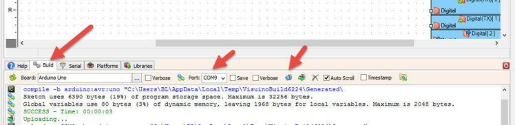
In Visuino, at the bottom click on the "Build" Tab, make sure the correct port is selected, then click on the "Compile/Build and Upload" button.
Step 9: PlayIf you power the Arduino module, The Red LED will glow, and if you enter the correct Code the Green LED will glow for 5 seconds, if you do not enter the right Code, the entered code will reset in 5 seconds and you can try it again.
Congratulations! You have completed your project with Visuino. Also attached is the Visuino project, that I created for this Instructable, you can download it here and open it in Visuino: https://www.visuino.eu
Schematics, diagrams and documents
Code
Credits
Related products


Leave your feedback...