
Apply a Filter
Category
- All
- 3D Printing
- Animals
- Art
- Artificial intelligence
- Astronomy
- Augmented Reality
- Automotive
- Bikes
- Clocks
- Communication
- Cryptocurrency
- Displays
- Drones
- Environmental Sensing
- Fire & Pyrotechnics
- Fitness
- Food & Drinks
- Games & Gaming
- Garden
- Health
- Holidays
- Home Automation
- IoT
- Kids & Family
- Lights
- Music
- Notifications
- Photos & Video
- Plants
- Productivity
- Retro Tech
- Robotics
- Security
- Sensors
- Sports
- Star Wars
- Sustainability
- Upcycling
- Vehicles
- Virtual Reality
- Voice
- Wearables
- Weather
Platform
- All
- 4D Systems
- 8bitcade
- Adafruit
- AIY
- AllThingsTalk
- Amazon Alexa
- Amazon Web Services
- Analog Devices
- Android
- Android Things
- Anycubic
- Apple
- Arduino
- Arm
- Arm Mbed
- Atlas Scientific
- Atmel
- Autodesk
- Avnet
- balena
- Bare Conductive
- BeagleBoard
- BITalino
- Blues Wireless
- Bluz
- Blynk
- Bolt IoT
- Bosch
- C.H.I.P
- circuito.io
- CircuitPython
- Commodore 8-bit
- ControlEverything.com
- Creator
- Cypress
- DeviceHub.net
- Dexter Industries
- DFRobot
- Digilent
- Digispark
- Eclipse IoT
- Edge Impulse
- EduBlocks
- Elecrow
- Electric Imp
- Elegoo
- Elephant Robotics
- Ender
- Espressif
- Espruino
- Everything ESP
- evive
- Firmware Modules
- GoPro
- Hackster's DeLorean
- HARDWARIO
- Helium
- Hologram
- Home Assistant
- Honeywell
- IBM
- ICStation
- Idiotware Shield
- IDT
- IFTTT
- Infineon
- Intel
- Itead
- Java
- JLCPCB
- Jupyter
- KiCad
- LabVIEW
- LattePanda
- Leap Motion
- LEGO MindStorms
- LeMaker
- Linux
- Linux Arm
- Losant
- M5Stack
- Mac
- Makeblock
- Makestro
- MATLAB
- MATRIX Labs
- Maxim Integrated
- Meadow
- MediaTek Labs
- micro:bit
- Microchip
- MicroPython
- Microsoft
- MikroE
- MikroElektronika
- MIT App Inventor
- Mouser
- MQTT
- myDevices
- nanoFramework
- NeoPixel
- Netduino
- Neuton Tiny ML
- noads
- Node-RED
- NodeMCU
- Nordic Semiconductor
- NVIDIA
- NVIDIA Jetson
- NXP
- Oculus
- ON Semiconductor
- Onion Corporation
- OpenBuilds
- OpenCat
- OpenCV
- OSH Park
- Panasonic
- Particle
- PCBWay
- Philips hue
- PHPoC
- Pi Supply
- Pimoroni
- PINE64
- PlatformIO
- Prusa
- Punch Through
- PX4
- Pycom
- Python
- Qualcomm
- RakWireless
- Raspberry Pi
- Red Pitaya
- RedBear
- Relayr
- Renesas
- RISC-V
- RobotGeek
- ROS
- RT-Thread
- Samsung IoT
- Seeed Studio
- SensiML
- Siemens
- Sigfox
- Silicon Labs
- SmartMatrix
- SmartThings
- Soldered Electronics
- Sony
- SparkFun
- STM32 Nucleo
- STMicroelectronics
- Taoglas
- Teensy
- TensorFlow
- Texas Instruments
- The Tactigon
- The Things Network
- Thinger.io
- Things On Edge
- thingSoC
- ThingSpeak
- TI LaunchPad
- TinyCircuits
- Tuya
- Twilio
- Ubidots
- Ubuntu
- UDOO
- Unity
- Visuino
- VoCore
- Walabot
- Weather Underground
- Wilderness Labs
- Windows
- WIZnet
- Xamarin
- XBee
- Xilinx
- Zerynth

Smart Pest Monitoring: Boosting Qsc Compliance & Operational
Detecting Tiny Targets inside the Insect trap box: AI Insect Monitoring at the Edge. 🪲🛠️
By
dave-chris
Easy
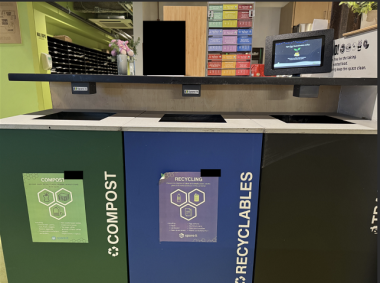
Zerooverflow Smartbin Solution For Smart City Management
Use Camthink NeoEye301 with Home Assistant to monitor the trash bin status and provide alert with high accuracy.
By
dave-chris
Moderate
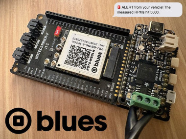
Monitoring Vehicle Can Data Over Obd-ii With Blues Notecard
Learn how to read vehicle diagnostic data directly from the OBD-II port and stream it to the cloud over cellular with a Blues Notecard.
By
RobLauer
Moderate
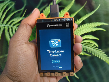
Build Diy Timelapse Camera With Unihiker K10
In this guide, you’ll build a sleek, automated timelapse camera using the UNIHIKER K10 by DFRobot—perfect for capturing long-term scenes.
By
rau7han
Easy
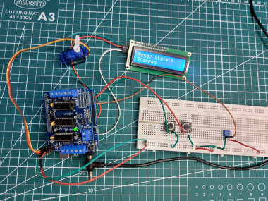
L293d Motor Driver Shield With Arduino
In this tutorial, you will learn about how to use an L293D motor driver shield with Arduino to control the speed and direction of rotation of motor
By
rachana-jain
Moderate
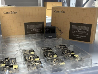
Smart Chip Monitor With Neoeyes Ne301
Build a real-time inventory tracker using CamThink NeoEye 301 & MQTT, featuring ultra-low power AI via Neural-ART NPU.
By
dave-chris
Moderate
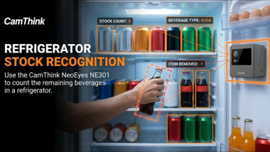
Edge Ai Camera For Automatic Drink Refill
CamThink smart camera + Home Assistant use Edge AI to detect drinks and trigger refills automatically.
By
dave-chris
Easy
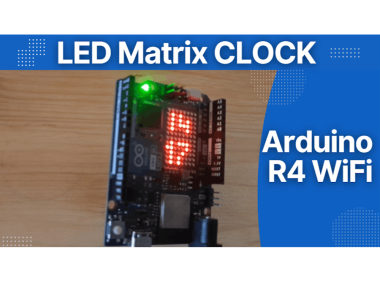
How To Make An Led Matrix Digital Clock With Arduino Uno R4
In this Visual Programming Visuino tutorial, we’ll use the Arduino Uno R4 WiFi’s built-in RTC and LED Matrix to create a digital clock.
By
Ron
Easy

Verify Banknotes Using Uv Light & Ir Sensor - Arduino
In this Visuino project, you will learn how to build a touchless banknote verification system using a high-efficiency UV LED module.
By
Ron
Easy
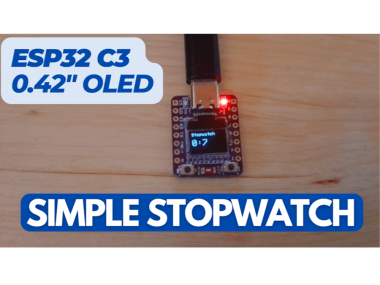
Make Esp32-c3 0.42″ Oled Stopwatch – Visual Programming
In this Visual Programming Visuino tutorial, we’ll use the ESP32-C3 development board with its built-in OLED display to create a stopwatch.
By
Ron
Easy
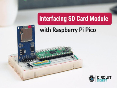
Raspberry Pi Pico Sd Card Spi Storage Interface
Expand your Pico with removable FAT32 storage — log data, manage files, and interact via a Serial menu using SPI and a microSD module.
Easy
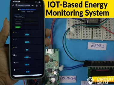
Iot Smart Energy Meter With Sms Alerts & Real-time Data
Monitor AC power metrics over Wi-Fi using ESP32 & PZEM-004T, view on MQTT dashboard, and receive SMS alerts on abnormal electrical condition
Easy
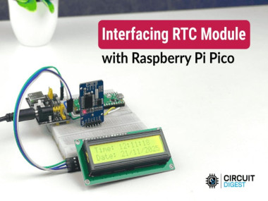
Accurate Timekeeping On Raspberry Pi Pico With Ds3231 Rtc
Build a reliable real-time clock with the Raspberry Pi Pico and DS3231 module, display time, date & temperature on I2C LCD, and learn syncin
Easy
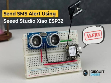
Compact Sms Alert System With Seeed Studio Xiao Esp32
Build a motion-activated SMS alert system using Seeed Studio XIAO ESP32, an ultrasonic sensor, and CircuitDigest Cloud SMS API, no GSM.
Easy
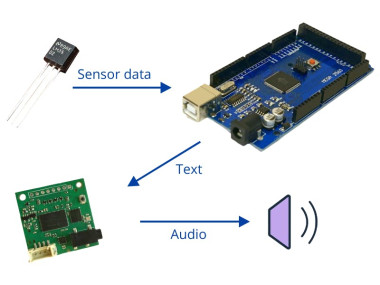
Offline Talking Sensor With Arduino And Tinytts
Add spoken feedback to any Arduino project by sending text and sensor values to a TinyTTS module over UART — no cloud, no audio files.
By
Grovety
Moderate

How To Scroll Text On Multiple Max7219 Led Matrix Displays
In this tutorial, we will build a scrolling text display using FC-16 LED matrix modules (MAX7219-based), an Arduino, and Visuino.
By
Ron
Moderate
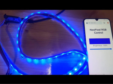
✨ Web-controlled Neopixel Led Ring With Esp32 And Visuino
In this tutorial, we will build a web-controlled NeoPixel LED ring using an Arduino Nano ESP32 and a WS2812B NeoPixel LED ring.
By
Ron
Moderate

Ambient Shifting Wave Lights With Arduino And Visuino
In this tutorial, you will learn how to make a decorative ambient lighting setup using 4 dimmable 5V retro light modules and an Arduino.
By
Ron
Easy