
Arduino Water Level Display – Real-time Level On I2c Lcd

Made by Ron / Displays / Environmental Sensing / Garden / Home Automation / IoT
About the project
In this Visuino project, you’ll learn how to easily measure and display water levels using a water level sensor and an I2C LCD
Project info
Difficulty: Easy
Platforms: Arduino, DFRobot, Visuino
Estimated time: 1 hour
License: GNU General Public License, version 3 or later (GPL3+)
Items used in this project
Hardware components

Software apps and online services
Story
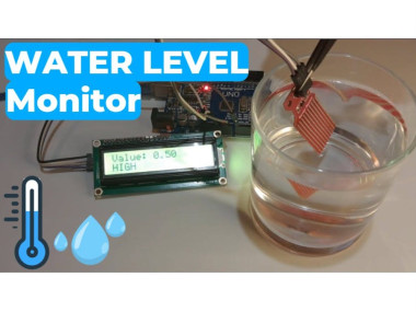
In this Visuino project, you’ll learn how to easily measure and display water levels using a water level sensor and an I2C LCD — all without writing a single line of code!
📟 The LCD shows the real-time water level value from 0.0 to 1.0 (so you can see any level in between, like 0.3 or 0.7).
💡 On the second row, it also displays a status label — Low, Medium, or High — based on the thresholds you set in Visuino.
Perfect for learning how to:
✅ Read water level using analog or digital sensors
✅ Display live readings and status on an LCD
✅ Build automatic monitoring or control systems
✅ Use Visuino visual programming to design Arduino projects fast and easily
📥 Download the Visuino project file at the bottom
🎥 Watch the full video to see it in action!
Step 1: What You Will Need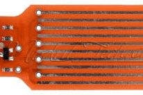
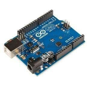
- Arduino UNO (Or any other Arduino)
- Water Level sensor
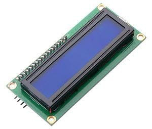
- LCD I2C Display
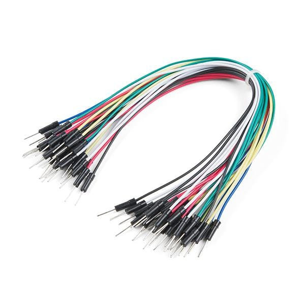
- Jumper wires
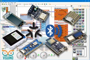
- Visuino program: Download Visuino

- Connect LCD Display pin [SCL] to Arduino pin [SCL]
- Connect LCD Display pin [SDA] to Arduino pin [SDA]
- Connect LCD Display pin [VCC] to Arduino pin [5v]
- Connect LCD Display pin [GND] to Arduino pin [GND]
- Connect Water Level Sensor pin[S] to Arduino analog pin[A0]
- Connect Water Level Sensor pin[-] to Arduino ground pin[GND]
- Connect Water Level Sensor pin[+] to Arduino positive pin[5V]

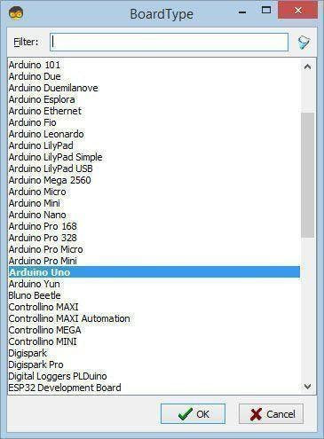
Start Visuino as shown in the first picture Click on the "Tools" button on the Arduino component (Picture 1) in Visuino When the dialog appears, select "Arduino UNO" as shown on Picture 2
Step 4: In Visuino Add Components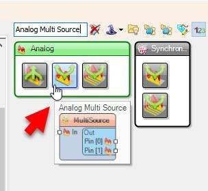
- Add "Analog Multi Source" component
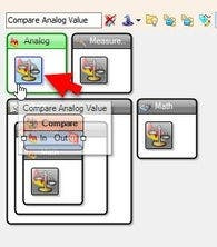
- Add 2X "Compare Analog Value" component
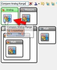
- Add "Compare Analog Range" component
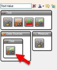
- Add "Text Value" component
- Add "Liquid Crystal Display (LCD) - I2C" component
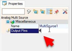

- Select "MultiSource1" and in the properties window set "Output Pins" to 4
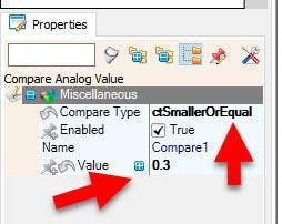
- Select "Compare1" and in the properties window set "Compare Type" to ctSmallerOrEqual and "Value" to 0.3 << this is the value for "LOW" level, adjust it according to your needs
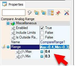
- Select "CompareRange1" and in the properties window set "Range">"Max" to 0.4 and "Range">"Min" to 0.3<< this is the value for "MEDIUM" level, adjust it according to your needs
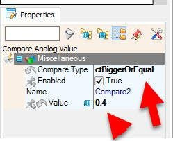
- Select "Compare2" and in the properties window set "Compare Type" to ctBiggerOrEqual and "Value" to 0.4 << this is the value for "HIGH" level, adjust it according to your needs
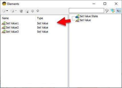
- Double click on the "TextValue1" and in the Elements window drag "Set Value" to the left side and in the properties window set "Value" to LOW
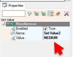
- Drag another "Set Value" to the left side and in the properties window set "Value" to MEDIUM
- Drag another "Set Value" to the left side and in the properties window set "Value" to HIGH
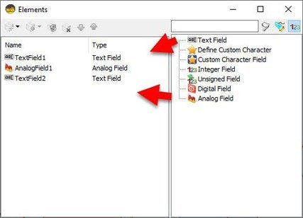
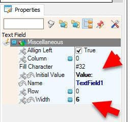
- Double click on the "LiquidCrystalDisplay1" and in the Elements window drag "Text Field" to the left side and in the properties window set "Initial Value" to VALUE: and "Width" to 6
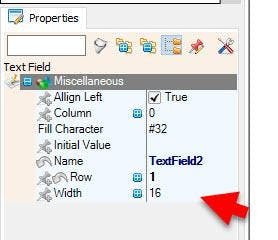
- Drag another "Text Field" to the left side and in the properties window set "Row" to 1
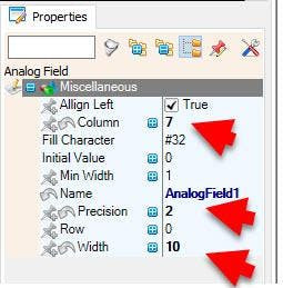
- in the Elements window drag "Analog Field" to the left side and in the properties window set "Column" to 7 and "Width" to 10 and "Precision" to 2
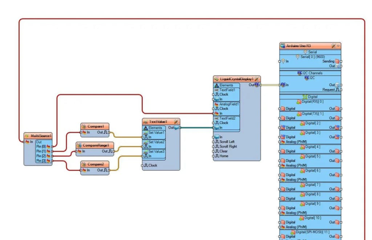
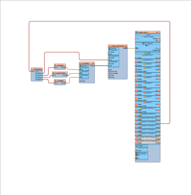
- Connect Arduino Analog pin [ 0 ] to "MultiSource1" pin [In]
- Connect "LiquidCrystalDisplay1" pin [I2C Out] to "Arduino.I2CChannels.I2C" pin [In]
- Connect "MultiSource1" Pin [0] to "LiquidCrystalDisplay1" > "AnalogField1" pin [In]
- Connect "MultiSource1" Pin [1] to "Compare1" pin [In]
- Connect "MultiSource1" Pin [2] to "CompareRange1" pin [In]
- Connect "MultiSource1" Pin [3] to "Compare2" pin [In]
- Connect "Compare1" pin [Out] to "TextValue1" > "Set Value1" Pin [In]
- Connect "CompareRange1" pin [Out] to "TextValue1" > "Set Value2" Pin [In]
- Connect "Compare2" pin [Out] to "TextValue1" > "Set Value3" Pin [In]
- Connect "TextValue1" Pin[Out] to "LiquidCrystalDisplay1" > "TextField2" pin [In]
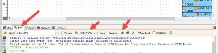
In Visuino, at the bottom click on the "Build" Tab, make sure the correct port is selected, then click on the "Compile/Build and Upload" button.
Step 8: PlayCongratulations! You have completed your project with Visuino. Also attached is the Visuino project, that I created for this tutorial, you can download it here and open it in Visuino: https://www.visuino.eu
Schematics, diagrams and documents
Code
Credits
Related products


Leave your feedback...