
Iot Based Pulse Oximeter Using Esp32

Made by raushan-kumar / 3D Printing / Communication / Displays / Fitness / IoT
About the project
In this project, I will show you how to make IoT based Pulse Oximeter using ESP32, MAX30100, and Blynk Application.
Project info
Items used in this project
Hardware components

Story
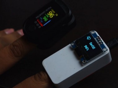
In this project, I will show you how to make IoT based Pulse Oximeter using ESP32, MAX30100, and Blynk Application.we can monitor those values from anywhere in the world using the Blynk IoT cloud platform.
As there is an availability of online data, so this project can be used to monitor the health of a patient online.
The pulse oximeter available in the market is very expensive, but with this simple & low-cost pulse oximeter module, we can make our own device. So let’s learn how to make MAX30100 Pulse Oximeter with ESP32.
Step 1: Required Components.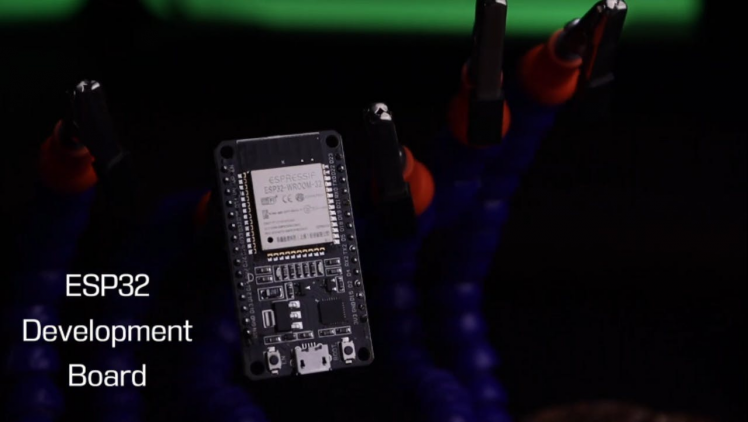

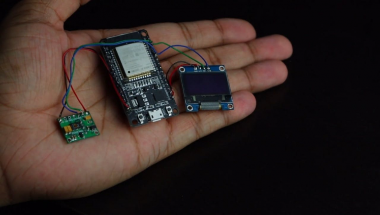
To make this IoT based Pulse oximeter you will need few componentsYou can buy all these components from the Amazon link (AFFILIATE LINK)ESP32 X1 ______________________________ INDIA /Amazon.com
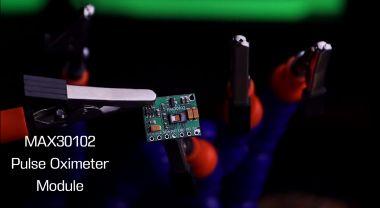
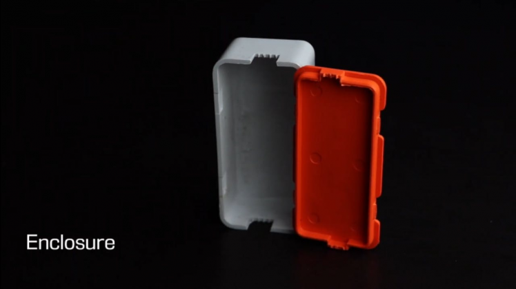
OLED Display X1 ______________________________ INDIA / Amazon.comPulse Oximeter Sensor X1 _________________________ INDIA /Amazon.com3D printed box X1
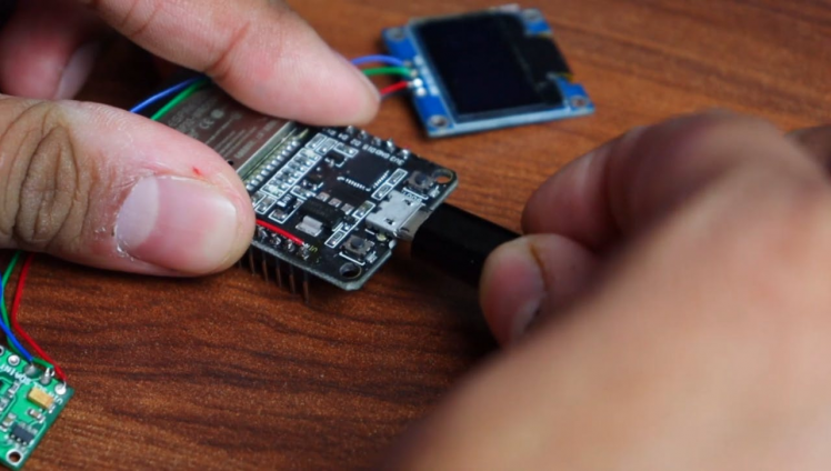
Just collect all the above Components.
Step 2: Working of MAX30100 Pulse Oximeter Sensor.

The sensor has two LEDs, one emitting red light, the other emitting infrared light. Infrared light is required for pulse rate. But, Both red light and infrared light are required for measuring Sp02 levels in the blood.
When the heart pumps the blood, the oxygen level is increased because there is more blood. But, when the heart rests, there is a decrease in oxygenated blood. Hence, the pulse rate is determined by getting the time between the rise and fall of oxygenated blood.
The oxygenated blood absorbs more infrared light and passes more red light. But, deoxygenated blood absorbs red light and passes more infrared light.
Basically, the MAX30100 sensor reads the absorption levels for both light sources and stores them in a buffer that can be read via I2C pins.
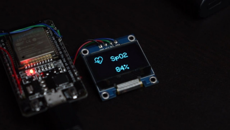
Step 3: 0.96″ I2C OLED Display.
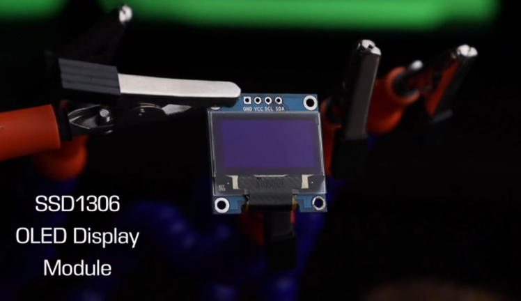
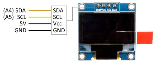
In the Display module, we will be using a 0.96 inch blue OLED display module.
We can easily interface this module with any microcontroller using SPI/I2C protocols.
The Display has a resolution of 128×64.
I2C OLED Displa
OLED stands for Organic Light-Emitting Diode. it’s a self light-emitting technology composed of a tiny, multi-layered organic film placed between an anode and cathode.
Unlike, LCD technology, OLED does not require a backlight.
OLED possesses high application potential for all types of displays. OLED is additionally considered the ultimate technology for the future generation of flat-panel display
Step 4: Interfacing MAX30100 Pulse Oximeter With ESP32.
circuit

circuit
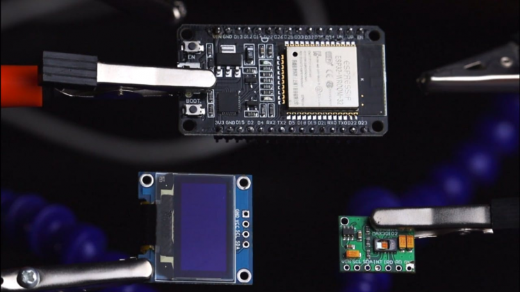
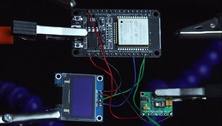
The Circuit assembly for this IoT Pulse oximeter is very simple.
Both OLED display and MAX30100 Oximeter Sensor works with the I2C. So, Interface the I2C pins (SCL &SDA) of both modules with D21 and D22 pins of ESP32.
Similarly, provide 3.3V power to the VCC and Ground the GND pin of both sensors. Basically, you can follow the circuit diagram to make your connections.
I won't go into too much detail, I have written some information on our blog.
Interfacing MAX30100 Pulse Oximeter With ESP32
5: Setting Up Blynk Application for IoT Pulse Oximeter
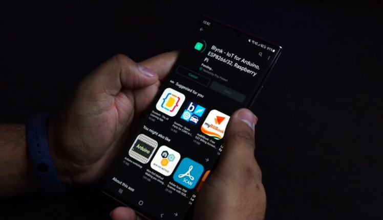
Now download this blink application from the play store/App store available for both Android and iOS.
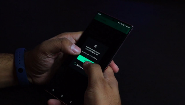
Sign up to the Blynk IoT cloud using your email address and password.
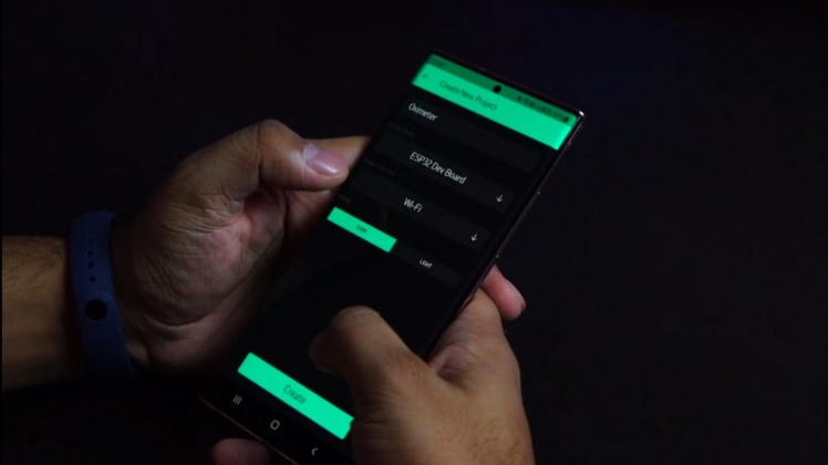
Now, click on the new project give your project a name. I am giving the “oximeter” select the ESP32 dev board and connection type as Wi-Fi. Then click on Create.
Now click on the “+” sign to add the widgets.
We need to read the value of BPM & SpO2. So select a pair of widget named Value Display & Gauge.
By the way, you go to our site and scan the code from it, you will get a pre-made widget, it will be easy for you
by clicking here ( Setting Up Blynk Application for IoT Pulse Oximeter )
Step 6: Software and Libraries
1 / 2
the hardware setup is done, now we need to upload the code to the NodeMCU ESP8266-12E Board. But before that you need to install few libraries.
The library files can be downloaded from here:
2. OLED Library
4. Blynk Simple
Step 7: CODE/*
## Hardware Connections (ESP32 <- OLED <- MAX 30102):
-VIN = 3.3V
-GND = GND
-SDA = 21 (or SDA)
-SCL = 22 (or SCL)
*/
/*================================================================================================================================== */
char auth[] = "qjZaiBBH26yK40yj29wXwZ8LXOoeQmtR";
char ssid[] = "nextpcb"; // Your WiFi Name (SSID) (**case sensitive).
char pass[] = "111222444" // Your WiFi Password.
/*================================================================================================================================== */
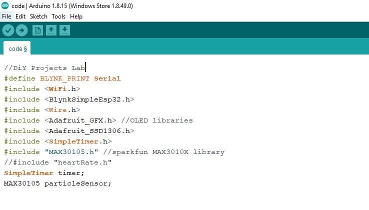
//DiY Projects Lab
#define BLYNK_PRINT Serial
#include <WiFi.h>
#include <BlynkSimpleEsp32.h>
#include <Wire.h>
#include <Adafruit_GFX.h> //OLED libraries
#include <Adafruit_SSD1306.h>
#include <SimpleTimer.h>
#include "MAX30105.h" //sparkfun MAX3010X library
//#include "heartRate.h"
SimpleTimer timer;
MAX30105 particleSensor;
#define INTERVAL_MESSAGE2 60000
unsigned long time_2 = 0;
int period = 2000;
unsigned long time_now = 0;
double avered = 0;
double aveir = 0;
double sumirrms = 0;
double sumredrms = 0;
int i = 0;
int Num = 100; //calculate SpO2 by this sampling interval
int oxygen;
double ESpO2 = 95.0; //initial value of estimated SpO2
double FSpO2 = 0.7; //filter factor for estimated SpO2
double frate = 0.95; //low pass filter for IR/red LED value to eliminate AC component
#define TIMETOBOOT 3000 // wait for this time(msec) to output SpO2
#define SCALE 88.0 //adjust to display heart beat and SpO2 in the same scale
#define SAMPLING 5 //if you want to see heart beat more precisely , set SAMPLING to 1
#define FINGER_ON 3000 // if red signal is lower than this , it indicates your finger is not on the sensor
#define MINIMUM_SPO2 0.0
const byte RATE_SIZE = 4; //Increase this for more averaging. 4 is good.
byte rates[RATE_SIZE]; //Array of heart rates
byte rateSpot = 0;
long lastBeat = 0; //Time at which the last beat occurred
float beatsPerMinute;
int beatAvg;
#define SCREEN_WIDTH 128 // OLED display width, in pixels
#define SCREEN_HEIGHT 64 // OLED display height, in pixels
#define OLED_RESET -1 // Reset pin # (or -1 if sharing Arduino reset pin)
Adafruit_SSD1306 display(SCREEN_WIDTH, SCREEN_HEIGHT, &Wire, OLED_RESET); //Declaring the display name (display)
//Logo2 and Logo3 are two bmp pictures that display on the OLED if called
static const unsigned char PROGMEM logo2_bmp[] =
{ 0x03, 0xC0, 0xF0, 0x06, 0x71, 0x8C, 0x0C, 0x1B, 0x06, 0x18, 0x0E, 0x02, 0x10, 0x0C, 0x03, 0x10,
0x04, 0x01, 0x10, 0x04, 0x01, 0x10, 0x40, 0x01, 0x10, 0x40, 0x01, 0x10, 0xC0, 0x03, 0x08, 0x88,
0x02, 0x08, 0xB8, 0x04, 0xFF, 0x37, 0x08, 0x01, 0x30, 0x18, 0x01, 0x90, 0x30, 0x00, 0xC0, 0x60,
0x00, 0x60, 0xC0, 0x00, 0x31, 0x80, 0x00, 0x1B, 0x00, 0x00, 0x0E, 0x00, 0x00, 0x04, 0x00,
};
static const unsigned char PROGMEM logo3_bmp[] =
{0x01, 0xF0, 0x0F, 0x80, 0x06, 0x1C, 0x38, 0x60, 0x18, 0x06, 0x60, 0x18, 0x10, 0x01, 0x80, 0x08,
0x20, 0x01, 0x80, 0x04, 0x40, 0x00, 0x00, 0x02, 0x40, 0x00, 0x00, 0x02, 0xC0, 0x00, 0x08, 0x03,
0x80, 0x00, 0x08, 0x01, 0x80, 0x00, 0x18, 0x01, 0x80, 0x00, 0x1C, 0x01, 0x80, 0x00, 0x14, 0x00,
0x80, 0x00, 0x14, 0x00, 0x80, 0x00, 0x14, 0x00, 0x40, 0x10, 0x12, 0x00, 0x40, 0x10, 0x12, 0x00,
0x7E, 0x1F, 0x23, 0xFE, 0x03, 0x31, 0xA0, 0x04, 0x01, 0xA0, 0xA0, 0x0C, 0x00, 0xA0, 0xA0, 0x08,
0x00, 0x60, 0xE0, 0x10, 0x00, 0x20, 0x60, 0x20, 0x06, 0x00, 0x40, 0x60, 0x03, 0x00, 0x40, 0xC0,
0x01, 0x80, 0x01, 0x80, 0x00, 0xC0, 0x03, 0x00, 0x00, 0x60, 0x06, 0x00, 0x00, 0x30, 0x0C, 0x00,
0x00, 0x08, 0x10, 0x00, 0x00, 0x06, 0x60, 0x00, 0x00, 0x03, 0xC0, 0x00, 0x00, 0x01, 0x80, 0x00};
#define USEFIFO
void setup()
{
Serial.begin(115200);
Serial.println("Initializing...");
display.begin(SSD1306_SWITCHCAPVCC, 0x3C); //Start the OLED display
display.display();
display.clearDisplay();
Blynk.begin(auth, ssid, pass);
// Initialize sensor
while (!particleSensor.begin(Wire, I2C_SPEED_FAST)) //Use default I2C port, 400kHz speed
{
Serial.println("MAX30102 was not found. Please check wiring/power/solder jumper at MH-ET LIVE MAX30102 board. ");
//while (1);
}
Serial.println("Place your index finger on the sensor with steady pressure.");
//Setup to sense a nice looking saw tooth on the plotter
byte ledBrightness = 255; // 0x7F Options: 0=Off to 255=50mA
byte sampleAverage = 4; //Options: 1, 2, 4, 8, 16, 32
byte ledMode = 2; //Options: 1 = Red only, 2 = Red + IR, 3 = Red + IR + Green
int sampleRate = 400; //1000 is best but needs processing power//Options: 50, 100, 200, 400, 800, 1000, 1600, 3200
int pulseWidth = 411; //Options: 69, 118, 215, 411
int adcRange = 16384; //Options: 2048, 4096, 8192, 16384
// Set up the wanted parameters
particleSensor.setup(ledBrightness, sampleAverage, ledMode, sampleRate, pulseWidth, adcRange); //Configure sensor with these settings
particleSensor.enableDIETEMPRDY();
timer.setInterval(500, sendUptime);
}
void sendUptime()
{
Blynk.virtualWrite(V4, oxygen);
//Blynk.virtualWrite(V5, beatAvg);
}
void loop()
{
Blynk.run();
timer.run(); // Initiates SimpleTimer
uint32_t ir, red, green;
double fred, fir;
double SpO2 = 0; //raw SpO2 before low pass filtered
#ifdef USEFIFO
particleSensor.check(); //Check the sensor, read up to 3 samples
while (particleSensor.available())
{ //do we have new data
#ifdef MAX30105
red = particleSensor.getFIFORed(); //Sparkfun's MAX30105
ir = particleSensor.getFIFOIR(); //Sparkfun's MAX30105
#else
red = particleSensor.getFIFOIR(); //why getFOFOIR output Red data by MAX30102 on MH-ET LIVE breakout board
ir = particleSensor.getFIFORed(); //why getFIFORed output IR data by MAX30102 on MH-ET LIVE breakout board
#endif
i++;
fred = (double)red;
fir = (double)ir;
avered = avered * frate + (double)red * (1.0 - frate); //average red level by low pass filter
aveir = aveir * frate + (double)ir * (1.0 - frate); //average IR level by low pass filter
sumredrms += (fred - avered) * (fred - avered); //square sum of alternate component of red level
sumirrms += (fir - aveir) * (fir - aveir); //square sum of alternate component of IR level
if ((i % SAMPLING) == 0)
{ //slow down graph plotting speed for arduino Serial plotter by thin out
if (millis() > TIMETOBOOT)
{
if (ir < FINGER_ON)
ESpO2 = MINIMUM_SPO2; //indicator for finger detached
//float temperature = particleSensor.readTemperatureF();
if (ESpO2 <= -1)
{
ESpO2 = 0;
}
if (ESpO2 > 100)
{
ESpO2 = 100;
}
oxygen = ESpO2;
Serial.print(" Oxygen % = ");
Serial.println(oxygen);
}
}
if ((i % Num) == 0)
{
double R = (sqrt(sumredrms) / avered) / (sqrt(sumirrms) / aveir);
// Serial.println(R);
SpO2 = -23.3 * (R - 0.4) + 100; //http://ww1.microchip.com/downloads/jp/AppNotes/00001525B_JP.pdf
ESpO2 = FSpO2 * ESpO2 + (1.0 - FSpO2) * SpO2; //low pass filter
//Serial.print(SpO2); Serial.print(","); Serial.println(ESpO2);
sumredrms = 0.0;
sumirrms = 0.0;
i = 0;
break;
}
particleSensor.nextSample(); //We're finished with this sample so move to next sample
//Serial.println(SpO2);
}
long irValue = particleSensor.getIR();
//Serial.println(irValue);
if (irValue > 7000)
{ //If a finger is detected
display.clearDisplay(); //Clear the display
display.drawBitmap(5, 5, logo2_bmp, 24, 21, WHITE); //Draw the first bmp picture (little heart)
display.setTextSize(2); //Near it display the average BPM you can display the BPM if you want
display.setTextColor(WHITE);
display.setCursor(50, 15);
display.println("SpO2");
display.setCursor(50, 50);
//display.println(beatAvg);
display.print(oxygen);
display.println("%");
display.display();
}
if (irValue == true)
{
display.clearDisplay(); //Clear the display
display.drawBitmap(0, 0, logo3_bmp, 32, 32, WHITE); //Draw the second picture (bigger heart)
display.setTextSize(2); //And still displays the average BPM
display.setTextColor(WHITE);
display.setCursor(50, 15);
display.println("SpO2");
display.setCursor(50, 50);
//display.println(beatAvg);
display.print(oxygen);
display.println("%");
display.display();
}
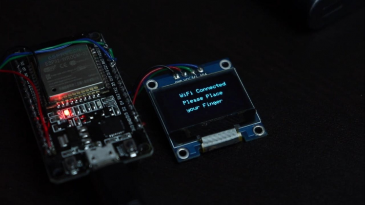
if (irValue < 7000)
{ //If no finger is detected it inform the user and put the average BPM to 0 or it will be stored for the next measure
//beatAvg=0;
display.clearDisplay();
display.setTextSize(1);
display.setTextColor(WHITE);
display.setCursor(30, 10);
display.println("WiFi Connected ");
display.setCursor(30, 25);
display.println("Please Place ");
display.setCursor(30, 4
0);
display.println("your Finger ");
display.display();
}
if (millis() > time_2 + INTERVAL_MESSAGE2 && oxygen < 93)
{
time_2 = millis();
Blynk.notify("Alert! Oxygen Saturation below 93% Detected");
Serial.print("Alert called");
}
#endif
}
1 / 3
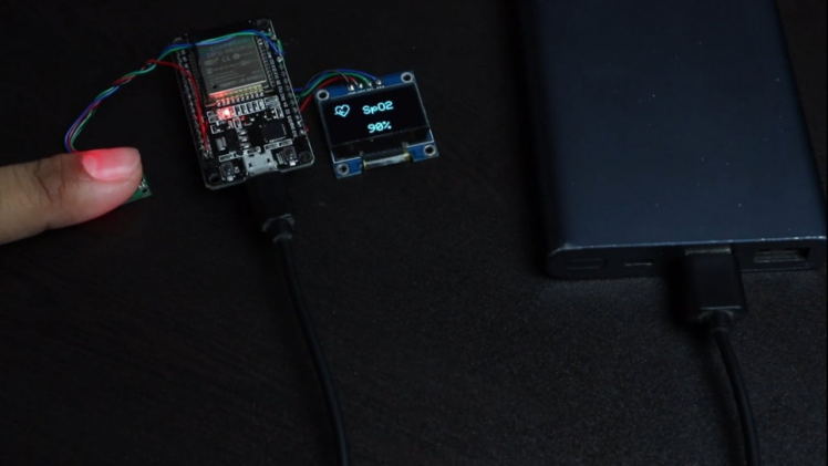
On the Android App, the BPM & SpO2 value is uploaded after a second and you can see a change in gauge and display parameters.
visit My website DiY Projects Lab having more than 25 awesome detailed projects
Step 9: DIY and BUY
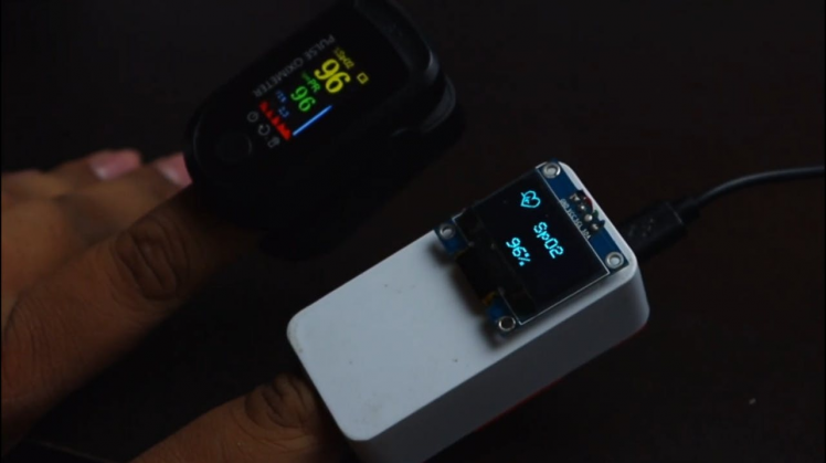
I compare my oximeter with professional one and its showing almost 99% accuracy.
Thank You NextPCB :This project is successfully completed because of the help and support from NextPCB.
Guys if you have a PCB project, please visit their website and get exciting discounts and coupons.
Here are midsummer sales at NextPCB
1. Up to 30% off for PCB oders
2. Up to 20% off for PCBA oders
Only 0$ for 5-10pcs PCB Prototypes https://www.nextpcb.com/
Thank you!
Schematics, diagrams and documents
Code
Credits
Related products


Leave your feedback...