
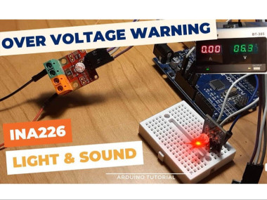
Ina226 Overvoltage Warning Light & Sound Using Arduino

About the project
In this tutorial we will learn how to make a overvoltage warning using the INA226 module, LED and a Piezo buzzer module. Watch the Video!
Project info
Difficulty: Easy
Estimated time: 1 hour
License: GNU General Public License, version 3 or later (GPL3+)
Items used in this project
Hardware components

Story
If the Voltage is below the 6V the Green LED will glow, if the Voltage is above the 6V the Red LED will glow and the piezo buzzer will beep. Voltage can be set according to your needs.
Watch the Video!
Step 1: What You Will Need1 / 5
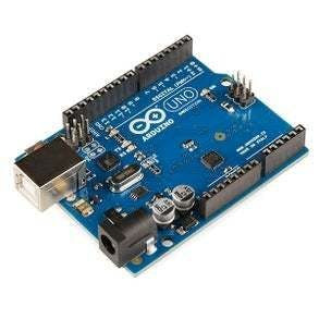


- Arduino Uno or any other Arduino board
- INA226 module More Info and here
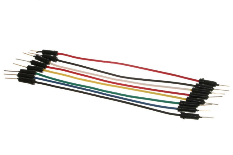
- Jumper wires
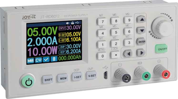
- (Optional) Power Supply to do the test
- Visuino software: Download here
1 / 2


Thank you PCBWay for supporting this tutorial and helping users learn more about electronics.
NEW! Now you can get Aluminum PCB & FLEX PCB in their Special Offer!
What I like about the PCBWay is that you can get 10 boards for approximately $5 which is really cost effective for professional made boards, not to mention how much time you save!
Go check them out here. They also offer a lot of other stuff in case you might need it like assembly,3D printing,CNC machining and a lot more.
Step 3: The Circuit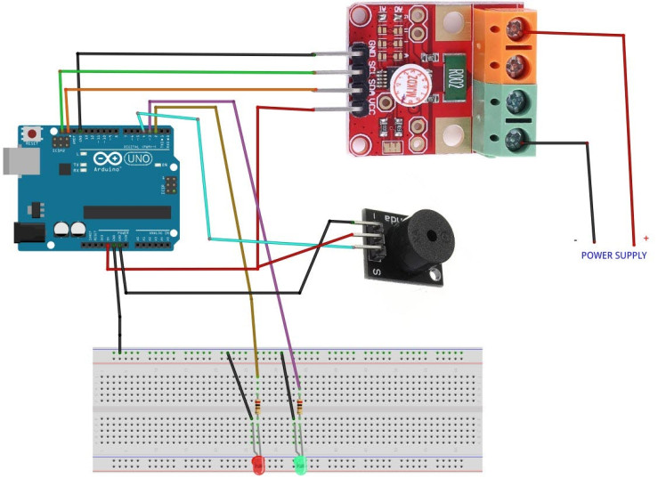
- Connect INA226 Module pin [SCL] to Arduino pin [SCL]
- Connect INA226 Module pin [SDA] to Arduino pin [SDA]
- Connect INA226 Module pin [VCC] to Arduino pin [5v]
- Connect INA226 Module pin [GND] to Arduino pin [GND]
- Connect Power Supply (or any Voltage source that you want to monitor) positive pin (+) to INA226 Module Pin (V+)
- Connect Power Supply (or any Voltage source that you want to monitor) negative pin (-) to INA226 Module Pin (V-)
- Connect Arduino Digital Pin [2] to 1k ohm resistor and connect the other side of the resistor to the Red LED positive pin [+]
- Connect the Red LED negative pin [-] to GND
- Connect Arduino Digital Pin [3] to 1k ohm resistor and connect the other side of the resistor to the Green LED positive pin [+]
- Connect the Green LED negative pin [-] to GND
- Connect Arduino Digital Pin [4] to Piezo buzzer module pin [S]
- Connect Arduino Pin [VCC] to Piezo buzzer module pin [+]
- Connect Arduino Pin [GND] to Piezo buzzer module pin [-]
1 / 2
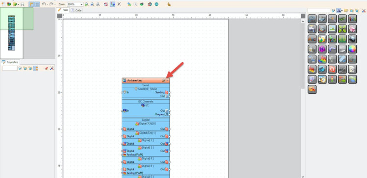
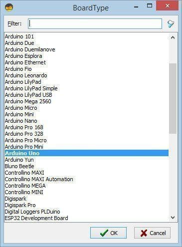
Start Visuino as shown in the first picture Click on the "Tools" button on the Arduino component (Picture 1) in Visuino When the dialog appears, select "Arduino UNO" as shown on Picture 2
Step 5: In Visuino Add Components1 / 4
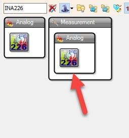
- Add "INA226" component
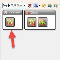
- Add "Digital Multi Source" component
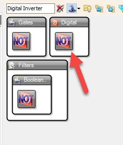
- Add "Digital Inverter" component
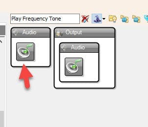
- Add "Play Frequency Tone" component
1 / 5
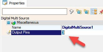
- Select "DigitalMultiSource1" and in the properties window set "Output pins" to 3
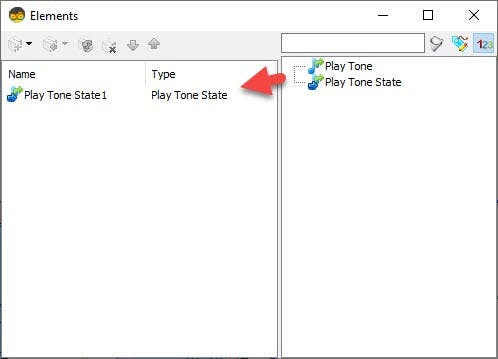
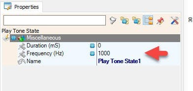
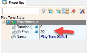
- Double click on the "PlayFrequency1" and in the Elements window drag "Play Tone State" to the Left side and in the properties window set "Frequency (Hz)" to 20
- Close the Elements window
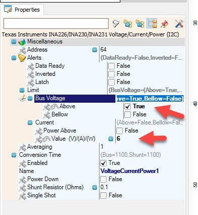
- Select "VoltageCurrentPower1" and in the properties window expand "Alerts">:Limit" and set "Above" to True
- Now expand "Alerts">:Limit">"Bus Voltage" and set "Value (V)/(A)/(W)" to 6 (or any other Voltage value that you need)
1 / 2
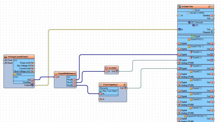
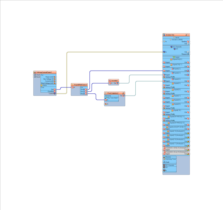
- Connect "VoltageCurrentPower1" pin I2C (Control) to Arduino Pin I2C (In)
- Connect "VoltageCurrentPower1" pin Limit (Out) to "DigitalMultiSource1" pin (In)
- Connect "DigitalMultiSource1" pin (0) to Arduino digital pin (2)
- Connect "DigitalMultiSource1" pin (1) to "Inverter1" pin (In)
- Connect "Inverter1" pin (Out) to Arduino digital pin (3)
- Connect "DigitalMultiSource1" pin (3) to "PlayFrequency1" > "Play Tone State1" pin (In)
- Connect "PlayFrequency1" pin (Out) to Arduino digital pin (4)
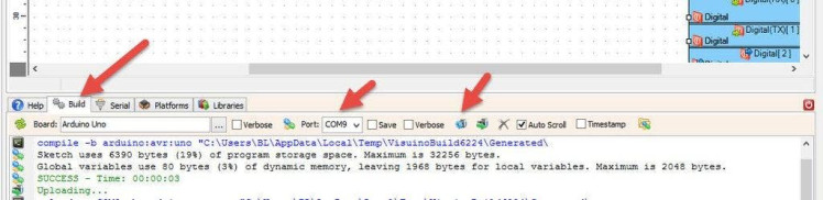
In Visuino, at the bottom click on the "Build" Tab, make sure the correct port is selected, then click on the "Compile/Build and Upload" button.
Step 9: PlayIf you power the Arduino module, The Green LED will glow and if the Voltage connected to the INA226 module is above the 6V a RED LED will glow and a buzzer module will beep.
Congratulations! You have completed your project with Visuino. Also attached is the Visuino project, that I created for this tutorial, you can download it and open it in Visuino: https://www.visuino.eu
Schematics, diagrams and documents
Code
Credits
Related products


Leave your feedback...