
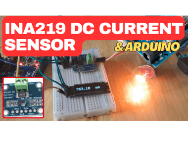
Ina219 Dc Current Sensor Using Visuino & Arduino

About the project
Learn how to use the INA219 DC Current Sensor with Visuino and Arduino to measure and display current in real time!
Project info
Difficulty: Easy
Estimated time: 1 hour
License: GNU General Public License, version 3 or later (GPL3+)
Items used in this project
Hardware components

Story
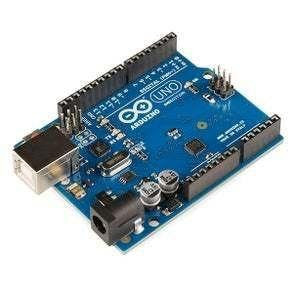
- Arduino UNO or any other Arduino board
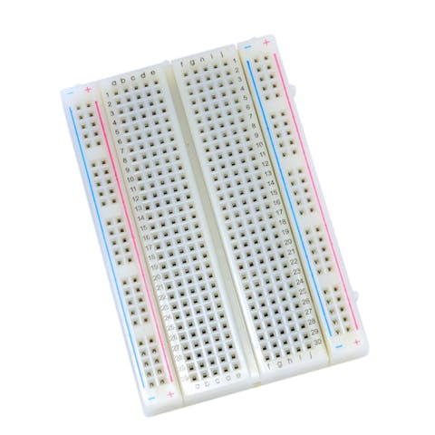
- Breadboard
- OLED Display
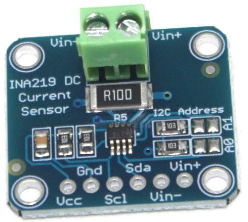
- INA219 DC Current Sensor
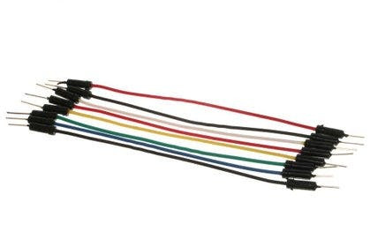
- Jumper wires
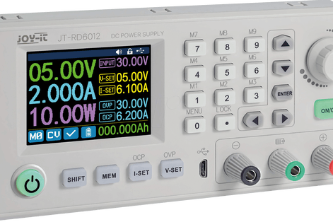
- Power Supply
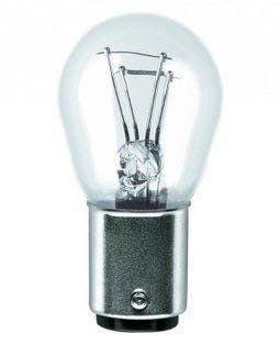
- Some load like a light bulb or DC motor
- Visuino software: Download here
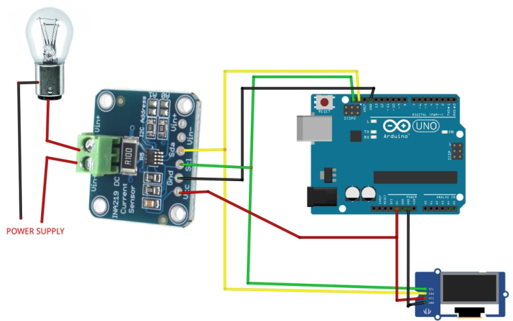
- Connect INA219 pin [SCL] to Arduino pin [SCL]
- Connect INA219 pin [SDA] to Arduino pin [SDA]
- Connect INA219 pin [VCC] to Arduino pin [5v]
- Connect INA219 pin [GND] to Arduino pin [GND]
- Connect OLED Display pin [SCL] to Arduino pin [SCL]
- Connect OLED Display pin [SDA] to Arduino pin [SDA]
- Connect OLED Display pin [VCC] to Arduino pin [5v]
- Connect OLED Display pin [GND] to Arduino pin [GND]
- Connect Power Supply (+) to INA219 pin [Vin -]
- Connect Light Bulb (+) to INA219 pin [Vin +]
- Connect Light Bulb (-) to Connect Power Supply (-)
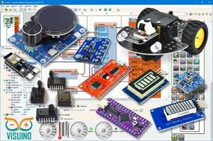
The Visuino: https://www.visuino.com also needs to be installed. Download Free version or register for a Free Trial.
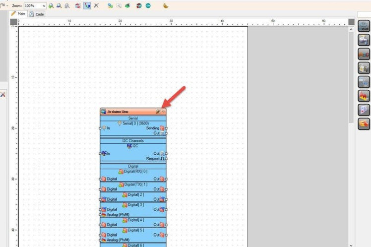
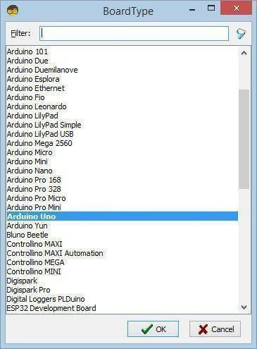
Start Visuino as shown in the first picture Click on the "Tools" button on the Arduino component (Picture 1) in Visuino When the dialog appears, select "Arduino UNO" as shown on Picture 2
Step 4: In Visuino Add, Set & Connect Components
- Add "INA219" component
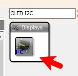
- Add "OLED I2C" component
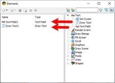
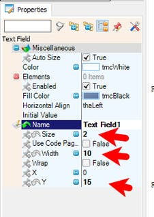
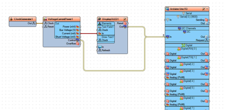
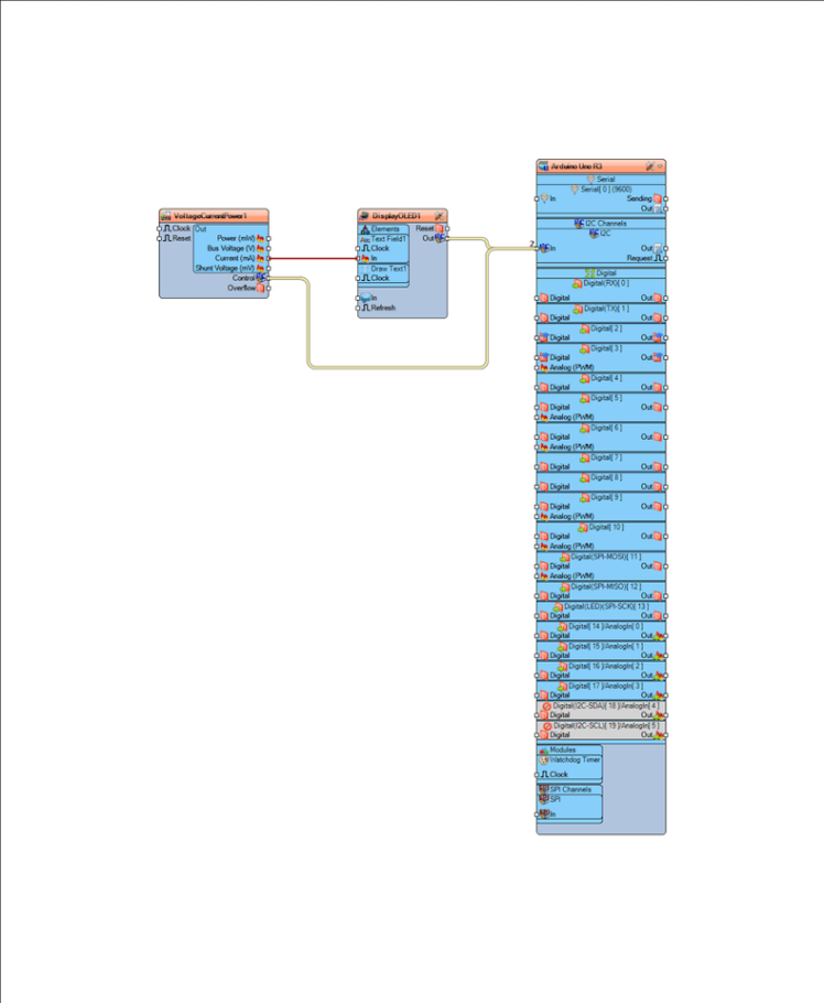
- Double click on the "DisplayOLED1" component and in the Elements window drag "Text Field" to the left side and in the properties window set "Size" to 2, "Width" to 10 and "Y" to 15
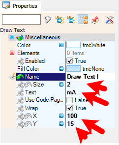
- in the Elements window drag "Draw Text" to the left side and in the properties window set "Size" to 2, "Text" to mA, "X" to 100 and "Y" to 15
- Close the Elements window
- Connect "VoltageCurrentPower1" pin [Current mA] to "DisplayOLED1" > "Text Field1" pin [In]
- Connect "VoltageCurrentPower1" Control pin [I2C] to Arduino pin [I2C]
- Connect "DisplayOLED1" pin [I2C] to Arduino pin [I2C]
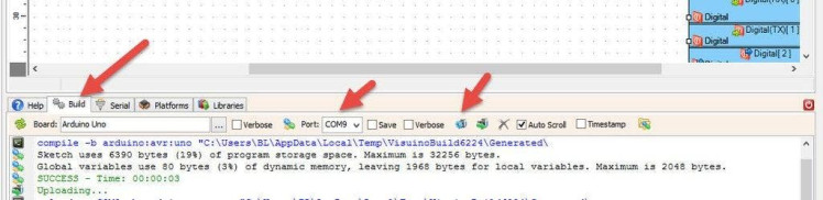
In Visuino, at the bottom click on the "Build" Tab, make sure the correct port is selected, then click on the "Compile/Build and Upload" button.
Step 6: PlayCongratulations! You have completed your project with Visuino. Also attached is the Visuino project, that I created for this Instructable, you can download it and open it in Visuino: https://www.visuino.com
Schematics, diagrams and documents
Code
Credits
Related products


Leave your feedback...