
I2c Matrix Keypad With Pcf8574/pcf8574a Gpio And Visuino

Made by Ron / Communication / Displays / Home Automation / Robotics / Sensors
About the project
Connect Matrix Keyboard using only 2 Arduino pins by using PCF8574/PCF8574A I2C GPIO - Quick and Easy!
Project info
Difficulty: Easy
Estimated time: 1 hour
License: GNU General Public License, version 3 or later (GPL3+)
Items used in this project

Software apps and online services
Story
Matrix Keypads are among the simplest and most popular ways to enter keyboard information into Arduino type micro-controllers. I already made a tutorial showing how you can connect Keypad to Arduino Nano. The downside is that to connect the keypad you will need to use 8 Digital Pins from the Arduino. This significantly reduces the pins available for other purpose. As I have shown in this tutorial, you can use I2C GPIO PCF8574/PCF8574A to add more pins to Arduino. You can use the same module to connect the Keypad, and use only 2 of the Arduino pins.
In this tutorial I will show you how easy it is to connect Matrix Keypad to Arduino with the help of I2C GPIO PCF8574/PCF8574A Module and program in with Visuino.
Step 1: Components
1 / 2 • Picture 1

Picture 1

Picture 2
- One Arduino compatible board (I use Arduino Nano, because I have one, but any other will be just fine)
- One PCF8574/PCF8574A GPIO Module (Also shown on Picture 2)
- One Matrix Keypad
- 4 Female-Female jumper wires
1 / 3 • Picture 1

Picture 1

Picture 2

Picture 3
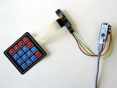
- Connect Female-Female wires - Power (Red wire), Ground (Black wire), SDA (Green wire), and SCL (Yellow wire) to the PCF8574/PCF8574A GPIO Module (Picture 1)
- Connect the other end of the Ground (Black wire) to the Ground pin of the Arduino board (Picture 2)
- Connect the other end of the Power (Red wire) to the 5V Power pin of the Arduino board (Picture 2)
- Connect the other end of the SDA wire (Green wire) to SDA/Analog pin 4 of the Arduino Nano board (Picture 2)
- Connect the other end of the SCL wire (Yellow wire) to SCL/Analog pin 5 of the Arduino Nano board (Picture 2)
-
Picture 3 shows where are the Ground, 5V Power, SDA/Analog pin 4, and SCL/Analog pin 5 pins of the
Arduino Nano
1 / 2 • Picture 1

Picture 1

Picture 2
Connect the Matrix Keypad connector to the pins P0 to P7 of the PCF8574/PCF8574A GPIO Module (Picture 1 and 2).
Step 4: Start Visuino, and select the Arduino Board type
1 / 2 • Picture 1

Picture 1

Picture 1
To start programming the Arduino, you will need to have the Arduino IDE installed from here: http://www.arduino.cc/.
Please be aware that there are some critical bugs in Arduino IDE 1.6.6.
Make sure that you install 1.6.7 or higher, otherwise this tutorial will not work!
The Visuino: https://www.visuino.com also needs to be installed.
- Start Visuino as shown in the first picture
- Click on the "Tools" button on the Arduino component (Picture 1) in Visuino
- When the dialog appears, select "Arduino Nano" as shown in Picture 2
1 / 4 • Picture 1

Picture 1

Picture 2

Picture 3

Picture 4
First we need to add component to control the PCF8574/PCF8574A GPIO:
- Type "gpio" in the Filter box of the Component Toolbox, then select the "PCF8574/PCF8574A GPIO" component (Picture 1), and drop it in the design area (Picture 2)
- In the Object Inspector, you may need to change the value of the "Address" property of the GPIO1 component (Picture 2) (See this tutorial for more details on selecting the I2C Address)
- The PCF8574 addresses are between 32 to 39 depending on the jumper settings
- The PCF8574A addresses are between 56 to 63 depending on the jumper settings
- Connect the "Out" pin of the GPIO1 component to the "In" pin of the "I2C" channel of the Arduino component (Picture 2)
- Type "keyp" in the Filter box of the Component Toolbox, then select the "Keypad" component (Picture 4), and drop it in the design area
1 / 5 • Picture 1

Picture 1

Picture 2

Picture 3

Picture 4

Picture 5
The Keypad component is very flexible and can contain variety of pins. It can contain Digital pins controlling individual digital values (On/Off) or character pins grouped in groups with common output. In this example we will add a group of character pins.
- Click on the "Tools" button on the Keypad1 component (Picture 1) to open the "Keys" editor (Picture 2)
- Select the "Character Key Group" on the right, and click on the "+" button on the left (Picture 2) to add one Character Key Group
- In the Object Inspector select the "Keys" property and click on the "..." button next to its value (Picture 3)
- Select the "Char Key" on the right, and click 16 times on the "+" button on the left (Picture 4) to add 16 Character Keys to the Group (Picture 5)
- Close the "Keys" editor dialog.
1 / 4 • Picture 1

Picture 1

Picture 2

Picture 3

Picture 4
Next we need to assign Character values to each key. We will start with the first row:
- In the Object Inspector expand the "Keys" property, then the "CharacterKeyGroup1" sub-property, then the "Keys" sub property, and finally the "Char Key1" sub-property (Picture 1)
- In the Object Inspector set the value of the "Character" sub-property of the "Char Key1" to "D" (Picture 1)
- In the Object Inspector expand the "Char Key2" sub-property, and set the value of the "Character" sub-property to "#" (Picture 2)
- In the Object Inspector expand the "Char Key3" sub-property, and set the value of the "Character" sub-property to "0" (Picture 3)
- In the Object Inspector expand the "Char Key4" sub-property, and set the value of the "Character" sub-property to "*" (Picture 4)
1 / 3 • Picture 1

Picture 1

Picture 2

Picture 3
Now we will continue assigning Character values to the remaining rows the same way as we did for the first row in the previous step:
- In the Object Inspector expand the "Char Key5" to "Char Key8" sub-properties, and set the values of their "Character" sub-properties to "C", "9", "8", "7" (Picture 1)
- In the Object Inspector expand the "Char Key9" to "Char Key12" sub-properties, and set the values of their "Character" sub-properties to "B", "6", "5", "4" (Picture 2)
- In the Object Inspector expand the "Char Key13" to "Char Key16" sub-properties, and set the values of their "Character" sub-properties to "A", "3", "2", "1" (Picture 3)
1 / 3 • Picture 1

Picture 1

Picture 2

Picture 3
- Connect the "Out" output pin of the "Keys.CharaterKeyGroup1" element of the Keypad1 component to the "In" input pin of the "Serial[ 0 ]" channel of the Arduino component (Picture 1)
- Click in the "Rows" box containing the pins of the Keypad1 component to start connecting all the Rows pins at once (Picture 2)
- Move the mouse over the "Out" output pin of the "Channel[ 4 ]" channel of the GPIO1 component. The Visuino will automatically spread the wires so they will connect correctly to the rest of the pins (Picture 2)
- Click in the "Columns" box containing the pins of the Keypad1 component to start connecting all the Columns pins at once (Picture 3)
- Move the mouse over the "In" input pin of the "Channel[ 0 ]" channel of the GPIO1 component. The Visuino will automatically spread the wires so they will connect correctly to the rest of the pins (Picture 3)
1 / 2 • Picture 1

Picture 1

Picture 2
- In Visuino, Press F9 or click on the button shown on Picture 1 to generate the Arduino code, and open the Arduino IDE
- In the Arduino IDE, click on the Upload button, to compile and upload the code (Picture 2)
1 / 2 • Picture 2

Picture 2

Picture 3
Congratulations! You have completed the project.
Picture 1 shows the connected and powered up project.
If you open Serial Terminal in the Arduino IDE or Visuino, and start typing on the Keypad, you will see the characters you type appear in the serial terminal (Picture 2)
On Picture 3 you can see the complete Visuino diagram.Also attached is the Visuino project, that I created for this Tutorial. You can download and open it in Visuino: https://www.visuino.com
Credits
Related products


Leave your feedback...