

How To Use Pcf8574 Gpio Extender With Arduino Or Esp32

Made by Ron / Communication / Environmental Sensing / Robotics / Sensors
About the project
If you require more pins for your project to connect more buttons, sensors or LEDs, GPIO expanders can help.
Project info
Difficulty: Easy
Estimated time: 1 hour
License: GNU General Public License, version 3 or later (GPL3+)
Items used in this project
Hardware components

Software apps and online services
Story
Essentially, these expanders offer additional GPIOs when your board doesn't provide enough pins.
In this tutorial we will learn how to use PCF8574 I2C GPIO Expander with Arduino UNO or ESP32
Watch the Video!
Also check out this amazing Visuino tutorials on how to use PCF8574 I2C GPIO Expander:
Arduino Nano: I2C Matrix Keypad With PCF8574/PCF8574A GPIO and Visuino : 11 Steps - Instructables
Step 1: What You Will Need1 / 6
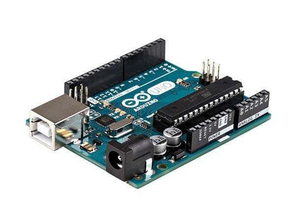

- Arduino UNO or ESP32 (Or any other Board)
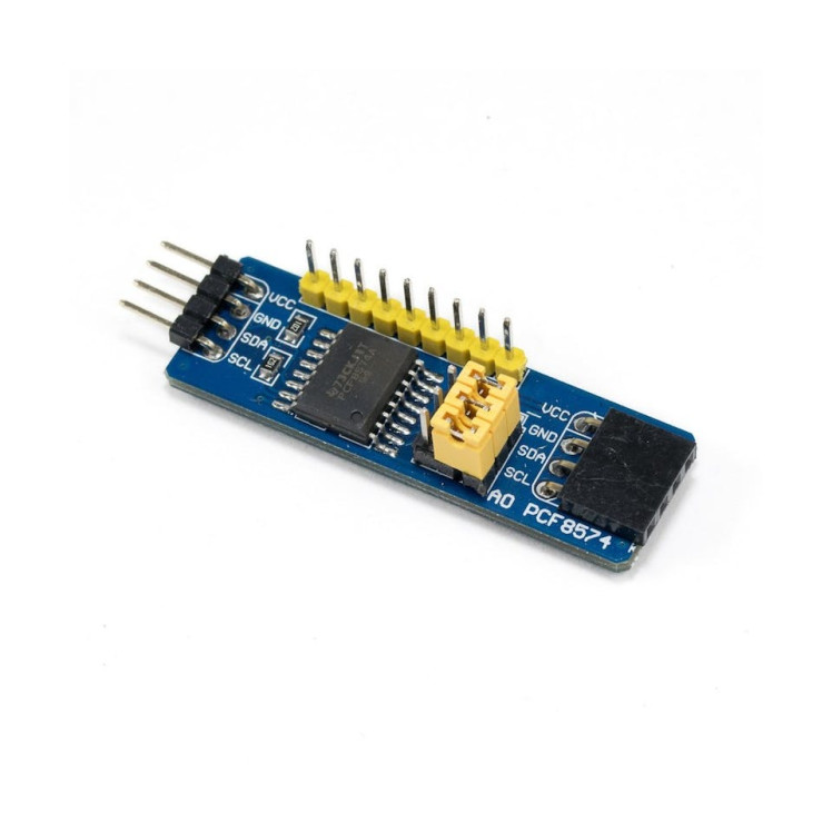
- PCF8574 I2C GPIO Expander
- To do the test experiment:
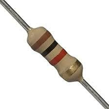
- 2x 1k ohm resistor
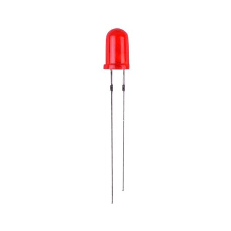
- LED
- Jumper wires
- Breadboard
- Visuino program: Download Visuino
1 / 2


Thank you PCBWay for supporting this tutorial and helping users learn more about electronics.
NEW! Now you can get Aluminum PCB & FLEX PCB in their Special Offer!
What I like about the PCBWay is that you can get 10 boards for approximately $5 which is really cost effective for professional made boards, not to mention how much time you save!
Go check them out here. They also offer a lot of other stuff in case you might need it like assembly,3D printing,CNC machining and a lot more.
Step 3: The Circuit Using Arduino UNO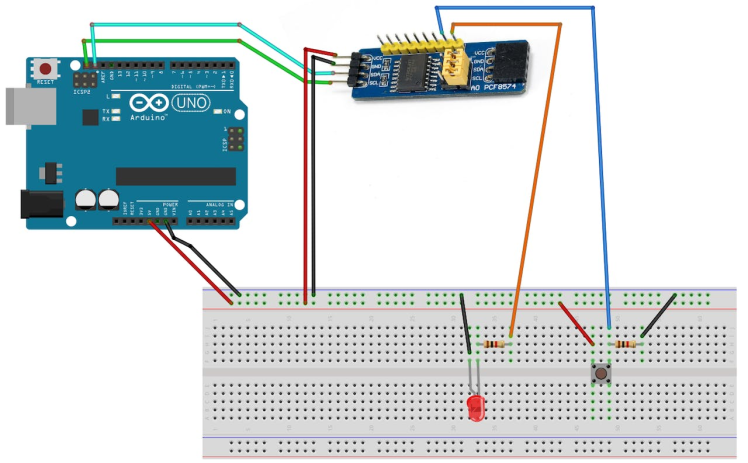
Connecting LED:
- Connect PCF8574 pin [0] to 1K ohm resistor on the breadboard
- Connect other side of the resistor to the LED pin [positive +]
- Connect LED pin [negative -] to the breadboard negative pin [Black line]
Connecting Button:
- Connect PCF8574 pin [1] to button on the breadboard and to the Resistor
- Connect other side of the resistor to the breadboard pin [GND]
- Connect Other pin of the button to the breadboard positive pin [5V]
- Connect Arduino pin [5V] to breadboard positive pin [Red line]
- Connect Arduino pin [GND] to breadboard negative pin [Black line]
Connecting PCF8574:
- Connect PCF8574 pin [VCC] to breadboard positive pin [Red line]
- Connect PCF8574 pin [GND] to breadboard positive pin [Black line]
- Connect PCF8574 pin [SCL] to Arduino pin [SCL]
- Connect PCF8574 pin [SDA] to Arduino pin [SDA]
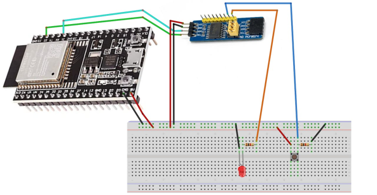
Connecting LED:
- Connect PCF8574 pin [0] to 1K ohm resistor on the breadboard
- Connect other side of the resistor to the LED pin [positive +]
- Connect LED pin [negative -] to the breadboard negative pin [Black line]
Connecting Button:
- Connect PCF8574 pin [1] to button on the breadboard and to the Resistor
- Connect other side of the resistor to the breadboard pin [GND]
- Connect Other pin of the button to the breadboard positive pin [5V]
- Connect ESP32 pin [5V] to breadboard positive pin [Red line]
- Connect ESP32 pin [GND] to breadboard negative pin [Black line]
Connecting PCF8574:
- Connect PCF8574 pin [VCC] to breadboard positive pin [Red line]
- Connect PCF8574 pin [GND] to breadboard positive pin [Black line]
- Connect PCF8574 pin [SCL] to ESP32 GPIO pin [22]
- Connect PCF8574 pin [SDA] to ESP32 GPIO pin [21]
1 / 3

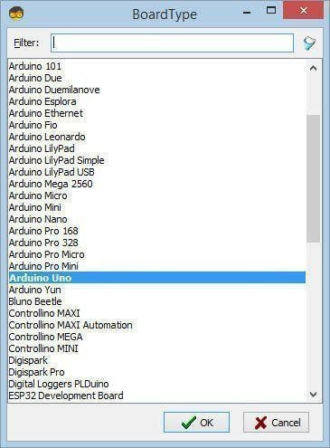
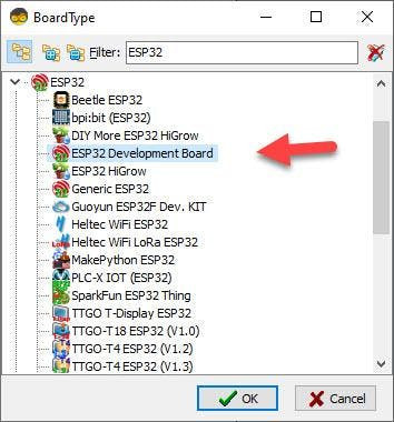
Start Visuino as shown in the first picture Click on the "Tools" button on the Arduino component (Picture 1) in Visuino When the dialog appears, select "Arduino UNO" as shown on Picture 2 or "ESP32 Development Board" as shown on Picture 3
Step 6: Experiment No.1 - in Visuino Add & Set Components1 / 6
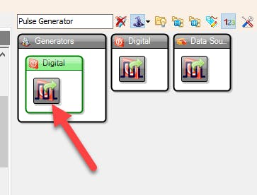
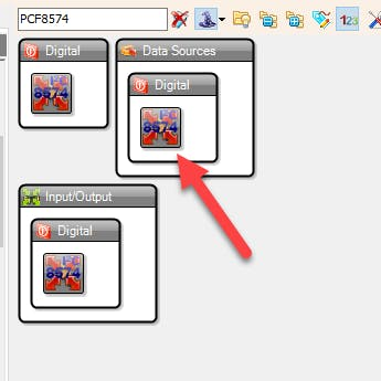
- Add "PCF8574" component
- Add "Pulse Generator" component
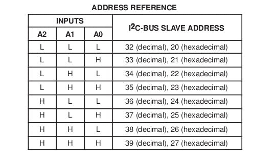
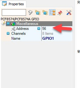
- Select "GPIO1" component and in the properties window set the I2C "Address", my module I2C Address was 32, you can check the pins on the module and compare it to the table as shown on Picture 4 or check the Step 7.
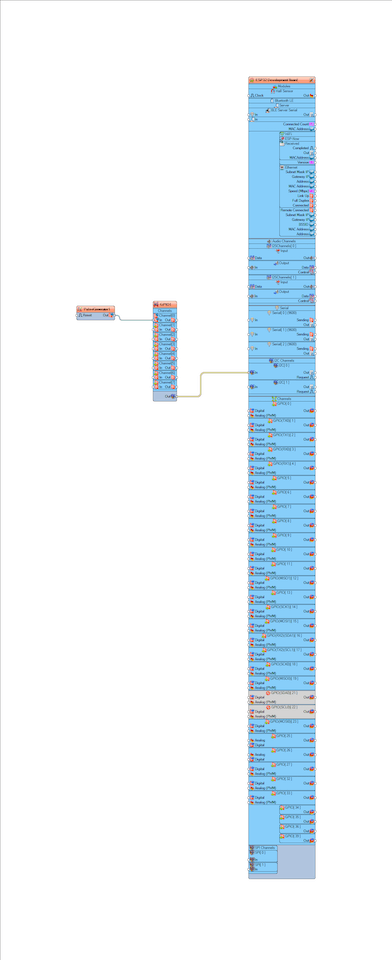
- Connect "PulseGenerator1" pin [Out] to "GPIO1" pin Channel 0 [In]
- Connect "GPIO1" pin I2C [Out] to the Board pin I2C [In]
- Upload the Project to the Board, see the "Generate, Compile, and Upload the Arduino Code" Step on how to upload the project
1 / 6
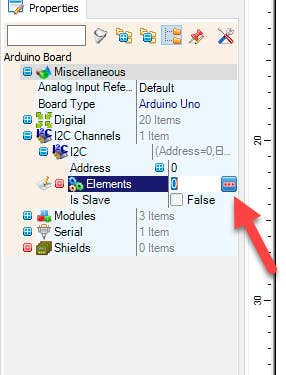
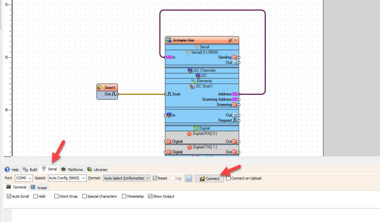
Make sure that the module is connected to the board correctly (pins VCC,GND,SCL,SDA)
- In Visuino select the board and in the properties window expand "I2C Channels" > "I2C" > "Elements" and click on the 3 dots button
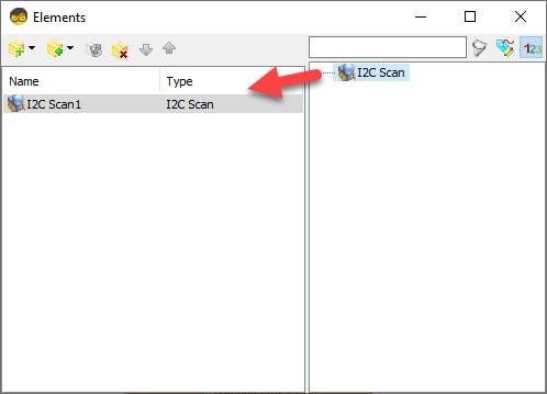
- In the "Elements" window Drag "I2C Scan" to the Left side
- Close the "Elements" window
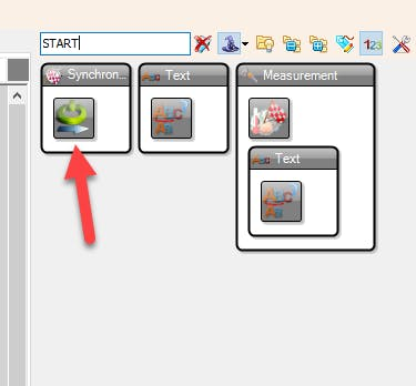
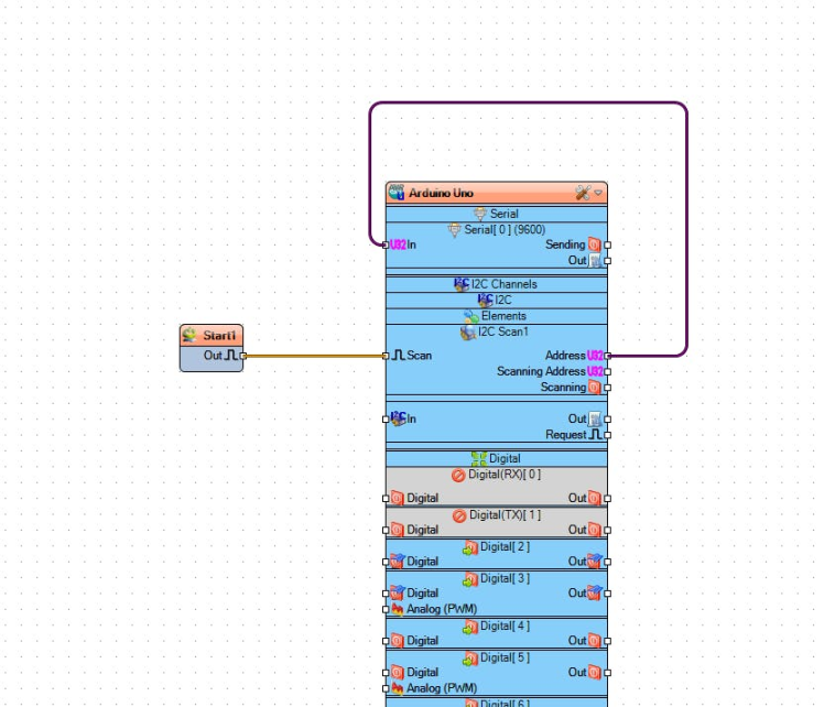
- Add "Start" component
- Connect "Start1" component to the board pin [Scan]
- Connect board pin [Address] to the board Serial pin 0 [In]
- Upload the Project to the Board, see the "Generate, Compile, and Upload the Arduino Code" Step on how to upload the project
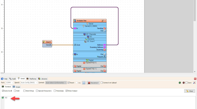
- Select the "Serial" tab and click "Connect" button and you should see the I2C Address of your module
1 / 6

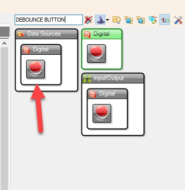
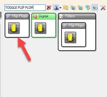


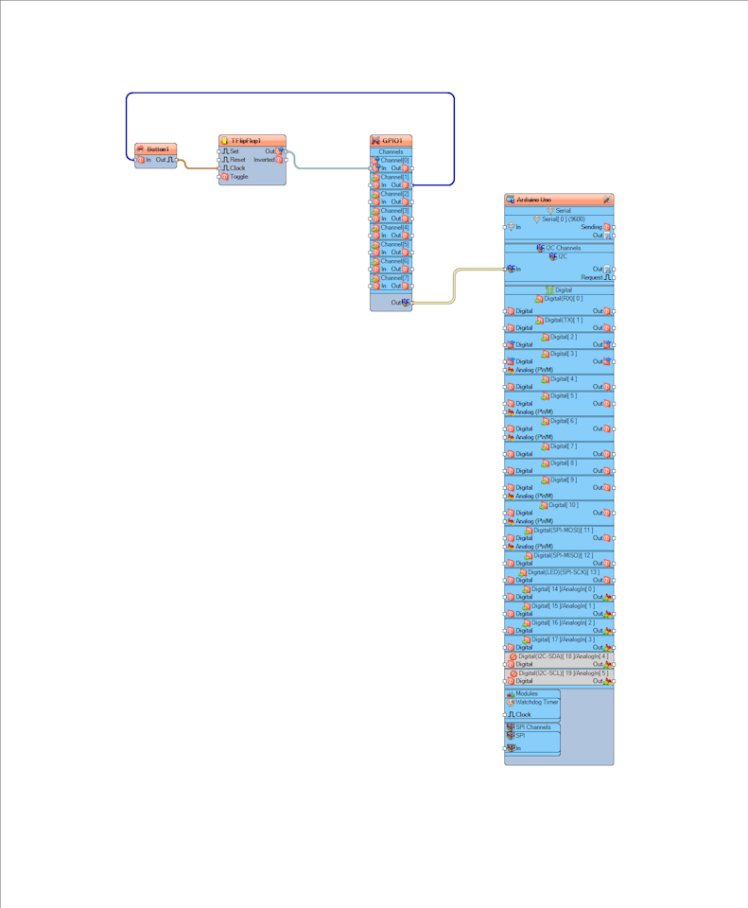
- Add "Debounce Button" component
- Add "Toggle Flip Flop" component
- Connect "GPIO1" pin Channel 2 [Out] to "Button1" pin [In]
- Connect "Button1" pin [Out] to "TFlipFlop1" pin [Clock]
- Connect "TFlipFlop1" pin [Out] to "GPIO1" pin Channel 1 [In]
- Connect "GPIO1" pin I2C [Out] to the Board pin I2C [In]
- Upload the Project to the Board, see the "Generate, Compile, and Upload the Arduino Code" Step on how to upload the project
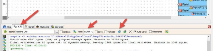
In Visuino, at the bottom click on the "Build" Tab, make sure the correct port is selected, then click on the "Compile/Build and Upload" button.
Note: If you are using a ESP32 dev board then hold the "BOOT" when uploading the project
Step 10: PlayIf you power the Board in Experiment No.1 the LED will Blink and in the Experiment No.2 the LED will turn On or Off if you press the button.
Congratulations! You have completed your project with Visuino. Also attached is the Visuino project, that I created for this project, you can download it here and open it in Visuino: https://www.visuino.eu
Schematics, diagrams and documents
Code
Credits
Related products


Leave your feedback...