
How To Use Mcp4725 12 Bit Digital To Analog Converter

Made by Ron / Communication / Displays / Notifications / Robotics / Sensors
About the project
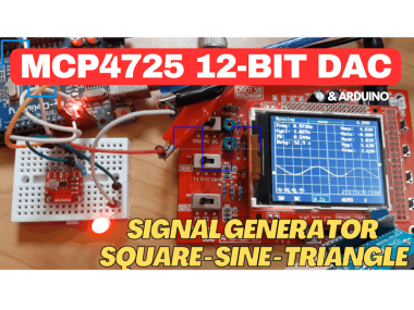
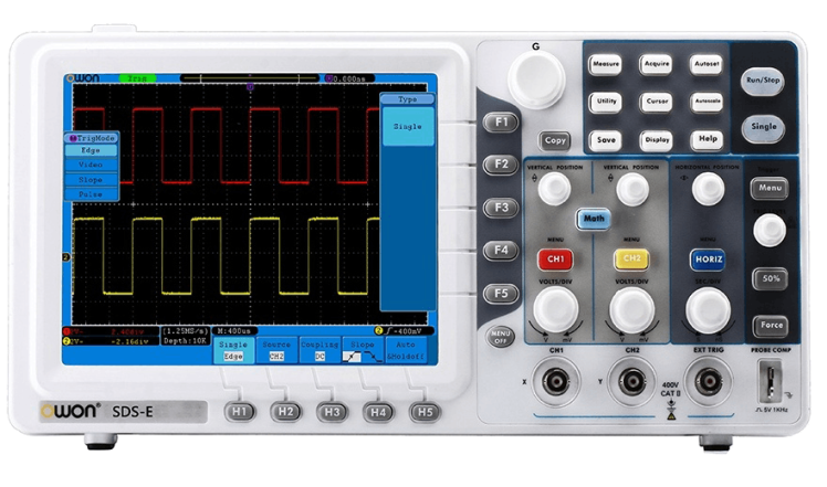
In this tutorial we will learn how to use MCP4725 12Bit Digital to Analog Converter with Arduino to generate Square, Sine & Triangle waves.
Project info
Difficulty: Easy
Platforms: Arduino, SparkFun, Visuino
Estimated time: 1 hour
License: GNU General Public License, version 3 or later (GPL3+)
Items used in this project
Hardware components

Software apps and online services
Story
1 / 7
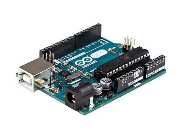
- Arduino UNO or ESP32 (Or any other Board)
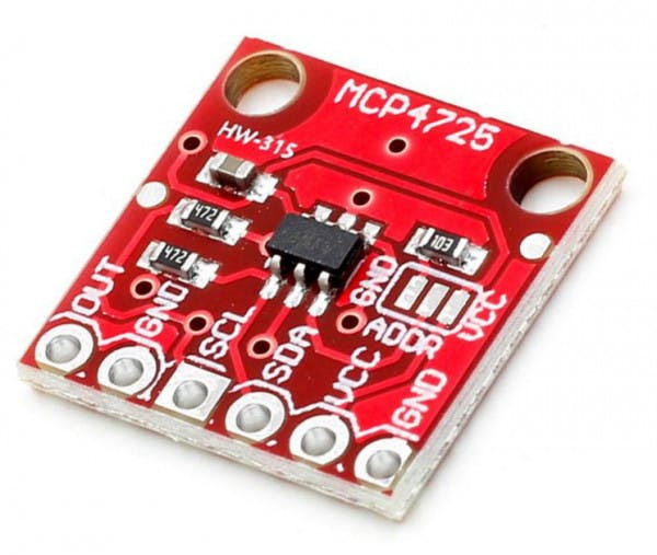
- MCP4725 module
- To do the test experiment:
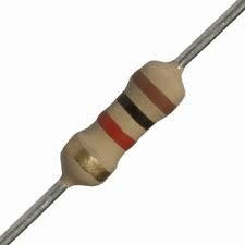
- 1k ohm resistor
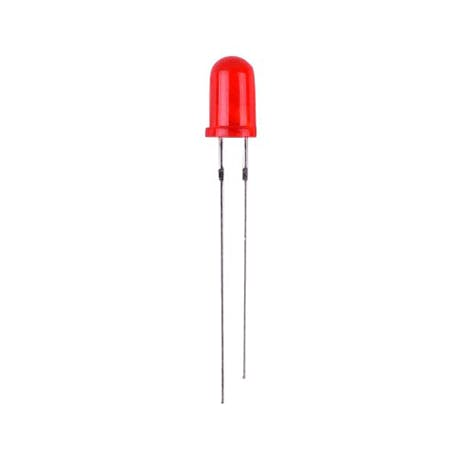
- LED
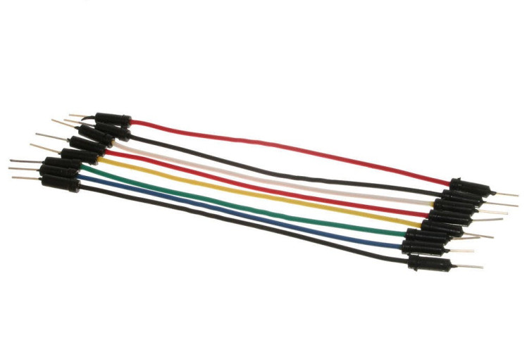
- Jumper wires
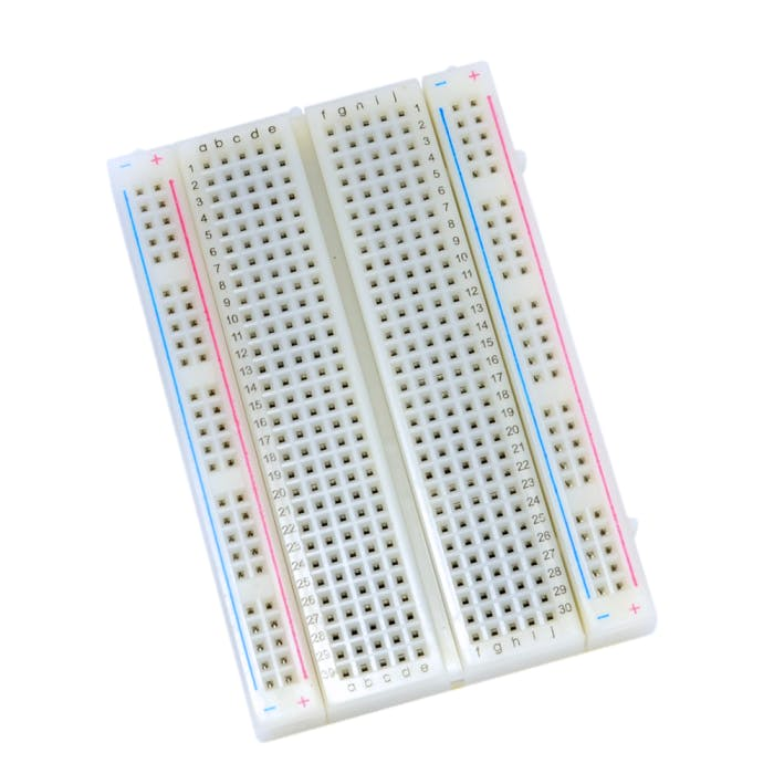
- Breadboard
- Oscilloscope (Optional)
- Visuino program: Download Visuino
1 / 2


Thank you PCBWay for supporting this tutorial and helping users learn more about electronics.
NEW! Now you can get Aluminum PCB & FLEX PCB in their Special Offer!
What I like about the PCBWay is that you can get 10 boards for approximately $5 which is really cost effective for professional made boards, not to mention how much time you save!
Go check them out here. They also offer a lot of other stuff in case you might need it like assembly,3D printing,CNC machining and a lot more.
Step 3: The Circuit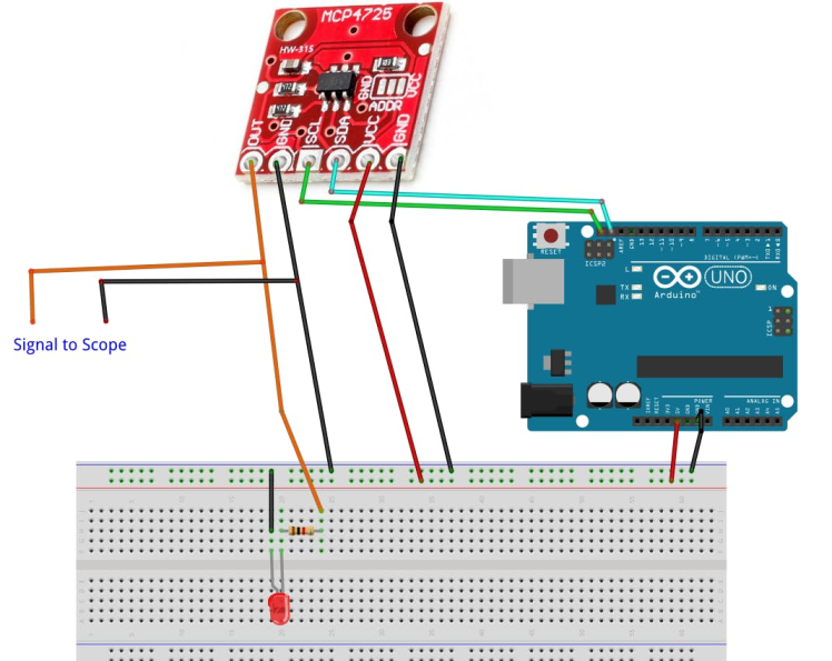
- Connect Arduino pin [5V] to breadboard positive pin [Red line]
- Connect Arduino pin [GND] to breadboard negative pin [Black line]
- Connect MCP4725 pin [Out] to 1K ohm Resistor on the breadboard
- Connect other side of the Resistor to the LED pin [positive +]
- Connect LED pin [negative - ] to the breadboard negative pin [Black line]
- Connect MCP4725pin [SCL] to Arduino pin [SCL]
- Connect MCP4725 pin [SDA] to Arduino pin [SDA]
- Connect MCP4725pin [VCC] to breadboard positive pin [Red line]
- Connect MCP4725pin [GND] to breadboard positive pin [Black line]
- Connect Oscilloscope Signal probe to MCP4725 pin [Out]
- Connect Oscilloscope Ground probe to breadboard positive pin [Black line]
1 / 2

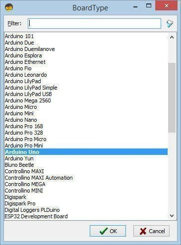
Start Visuino as shown in the first picture Click on the "Tools" button on the Arduino component (Picture 1) in Visuino When the dialog appears, select "Arduino UNO" as shown on Picture 2
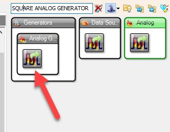
Step 5: Generate Square Waves - in Visuino Add & Set Components1 / 3

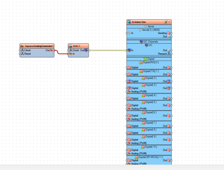
- Add "Microchip I2C Digital To Analog Converter (DAC) - MCP4725" component
- Add "Square Analog Generator" component
- Connect "SquareAnalogGenerator1" pin [Out] to "DAC1" pin [In]
- Connect "DAC1" pin I2C [Out] to the Arduino Board pin I2C [In]
- Upload the Project to the Board, see the "Generate, Compile, and Upload the Arduino Code" Step on how to upload the project
1 / 4

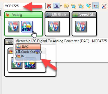
- Add "Microchip I2C Digital To Analog Converter (DAC) - MCP4725" component
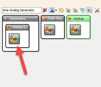
- Add "Sine Analog Generator" component
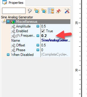
- Set the "Frequency" in the Properties window to 0.2
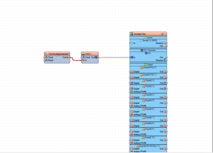
- Connect "SineAnalogGenerator1" pin [Out] to "DAC1" pin [In]
- Connect "DAC1" pin I2C [Out] to the Arduino Board pin I2C [In]
- Upload the Project to the Board, see the "Generate, Compile, and Upload the Arduino Code" Step on how to upload the project
1 / 3
- Add "Microchip I2C Digital To Analog Converter (DAC) - MCP4725" component
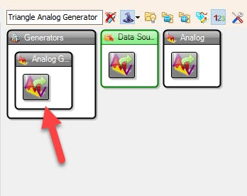
- Add "Triangle Analog Generator" component
- [Optional] Set the "Frequency" in the Properties window
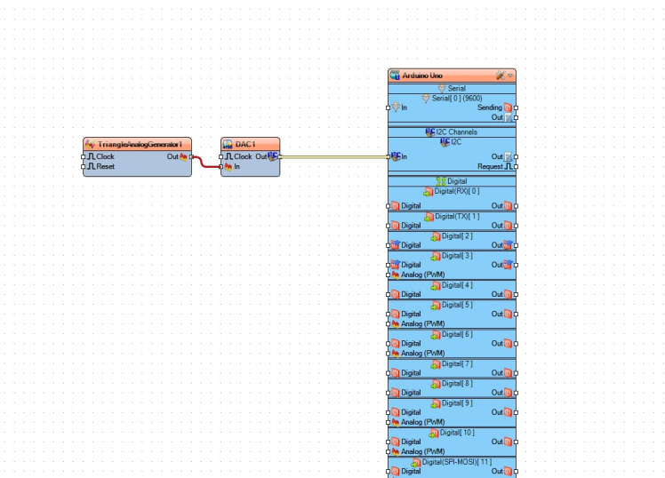
- Connect "TriangleAnalogGenerator1" pin [Out] to "DAC1" pin [In]
- Connect "DAC1" pin I2C [Out] to the Arduino Board pin I2C [In]
- Upload the Project to the Board, see the "Generate, Compile, and Upload the Arduino Code" Step on how to upload the project
1 / 4
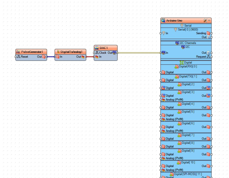
- In this Example we are going to convert digital pulses from "Pulse Generator" component to Analog Signal using a "Digital To Analog" component
- Add "Microchip I2C Digital To Analog Converter (DAC) - MCP4725" component
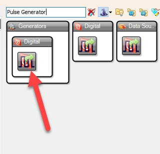
- Add "Pulse Generator" component
- [Optional] Set the "Frequency" in the Properties window
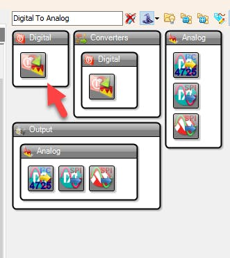
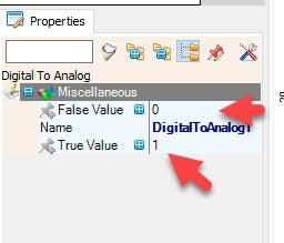
- Add "Digital To Analog" component
- [Optional] Set the "True" or "False" values in the Properties window
- Connect "PulseGenerator1" pin [Out] to "DigitalToAnalog1" pin [In]
- Connect "DigitalToAnalog1" pin [Out] to "DAC1" pin [In]
- Connect "DAC1" pin I2C [Out] to the Arduino Board pin I2C [In]
- Upload the Project to the Board, see the "Generate, Compile, and Upload the Arduino Code" Step on how to upload the project
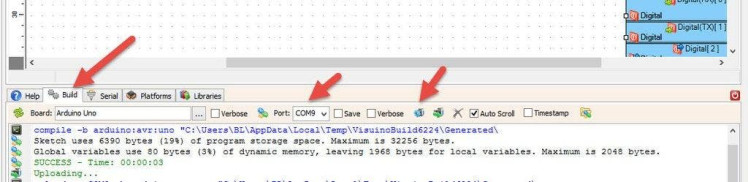
In Visuino, at the bottom click on the "Build" Tab, make sure the correct port is selected, then click on the "Compile/Build and Upload" button.
Step 10: PlayIf you power the Board LED will Blink and if you are using an oscilloscope you should see the signal from the MCP4725 module. There are many ways to use this module this was just a quick simple introduction to get started.
Congratulations! You have completed your project with Visuino. Also attached is the Visuino project, that I created for this Instructable, you can download it here and open it in Visuino: https://www.visuino.eu
Schematics, diagrams and documents
Code
Credits
Related products


Leave your feedback...