
How To Save Sensor Data Temp & Time To Sd Card Using Arduino

Made by Ron / Clocks / Environmental Sensing / Home Automation / Sensors / Weather
About the project
In this tutorial we are going to save Temperature, Humidity Data from the Dht11 sensor & Date Time to the SD card.
Project info
Difficulty: Easy
Platforms: Arduino, DFRobot, Seeed Studio, Visuino
Estimated time: 1 hour
License: GNU General Public License, version 3 or later (GPL3+)
Items used in this project
Hardware components

Story
In this tutorial we are going to save Temperature and Humidity data from the Dht11 sensor to the SD card and we will also add a time and a date that we will get from the RTC module ds1307.
Watch the Video!
Step 1: What You Will Need- Arduino UNO (or any other Arduino or ESP)
- SD Card module + SD card to store data
- DHT11 Temperature & Humidity sensor
- RTC DS1307 module
- Jumper wires
- Breadboard
- Visuino program: Download Visuino
Step 2:Brought by PCBWay

Thank you PCBWay for supporting this tutorial and helping users learn more about electronics.
What I like about the PCBWay is that you can get 10 boards for approximately $5 which is really cost effective for professional made boards, not to mention how much time you save!
Go check them out here. They also offer a lot of other stuff in case you might need it like assembly, 3D printing, CNC machining and a lot more.
Step 3: The circuit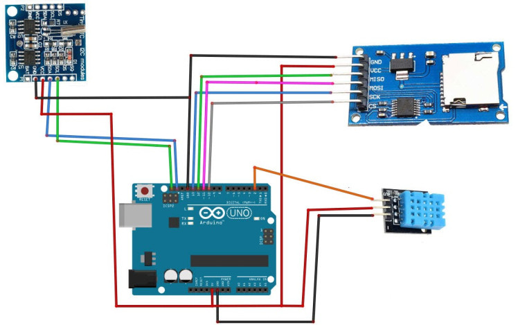
- Connect SD card Module pin GND to Arduino pin GND
- Connect SD card Module pin VCC to Arduino pin 5V
- Connect SD card Module pin SCK to Arduino digital pin 13
- Connect SD card Module pin MISO to Arduino digital pin 12
- Connect SD card Module pin MOSI to Arduino digital pin 11
- Connect SD card Module pin CS to Arduino digital pin 10
- Connect RTC DS1307 module pin[VCC] to Arduino pin[5V]
- Connect RTC DS1307 module pin[GND] to Arduino pin[GND]
- Connect RTC DS1307 module pin[SDA] to Arduino pin[SDA]
- Connect RTC DS1307 module pin[SCL] to Arduino pin[SCL]
- Connect DHT11 sensor pin [VCC] to Arduino pin [5V]
- Connect DHT11 sensor pin [GND] to Arduino pin [GND]
- Connect DHT11 sensor pin [OUT] to Arduino Digital pin [2]
1 / 2
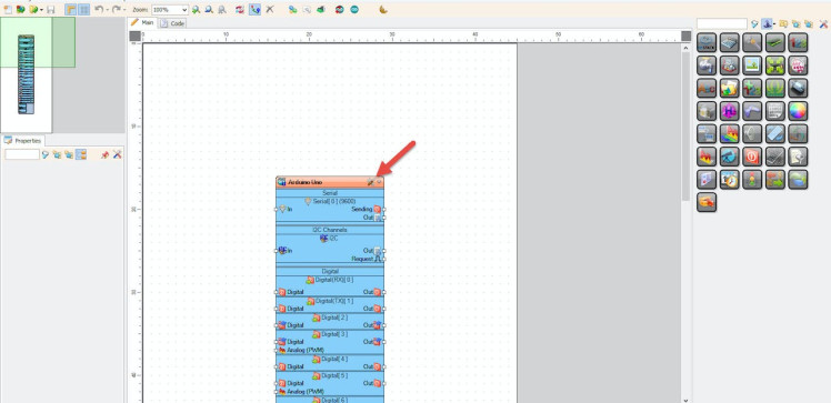
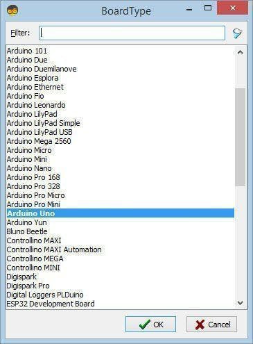
Start Visuino as shown in the first picture Click on the "Tools" button on the Arduino component (Picture 1) in Visuino When the dialog appears, select "Arduino UNO" as shown on Picture 2
Step 5: In Visuino Add Components1 / 6
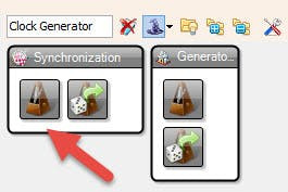
- Add "Clock Generator" component
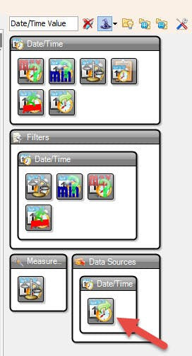
- Add "Date/Time Value" component
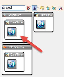
- Add "Real Time Clock DS1307" component
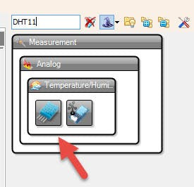
- Add "DHT11" component
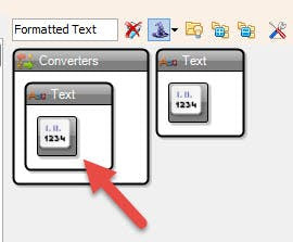
- Add "Formatted Text" component
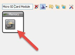
- Add "Micro SD Card Module" component
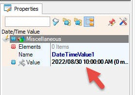
- Select "DateTimeValue1" and in the properties window select "Value" and set your current Date & Time
- Select "ClockGenerator1" and in the properties window set "Frequency" to 0.1 this means that the Data will be stored every 10 s
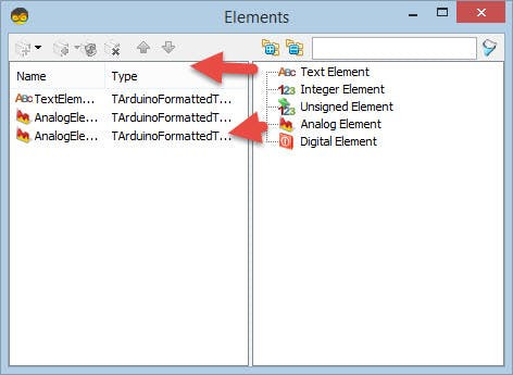
- Double click on the "FormattedText1" and in the "Elements" window drag "Text Element" & 2X "Analog Element" to the left side.
- Close the "Elements Window"
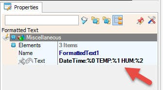
- Select "FormattedText1" and in the "properties window select "Text" and type DateTime:%0 TEMP:%1 HUM:%2
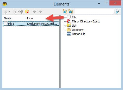
- Double click on the "SDCard1" and in the "Elements" window drag "File" to the left side.and in the properties window select "Path Name" and type SENSDATA.txt
- Close the "Elements Window"
1 / 5

1 / 3
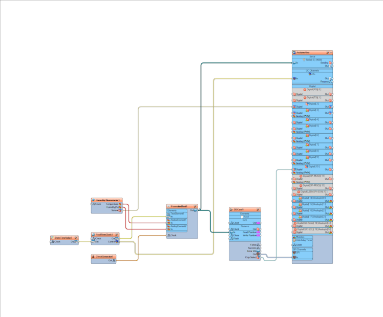
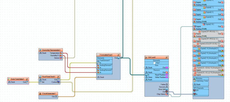
- Connect "DateTimeValue1" pin [Out] to "RealTimeClock1" pin [Set]
- Connect "HumidityThermometer1" pin [Temperature] to "FormattedText1 > AnalogElement1" pin [In]
- Connect "HumidityThermometer1" pin [Humidity] to "FormattedText1 > AnalogElement2" pin [In]
- Connect "RealTimeClock1" pin [Our] to "FormattedText1 > Text Element1" pin [In]
- Connect "ClockGenerator1" pin [Our] to "FormattedText1" pin [Clock]
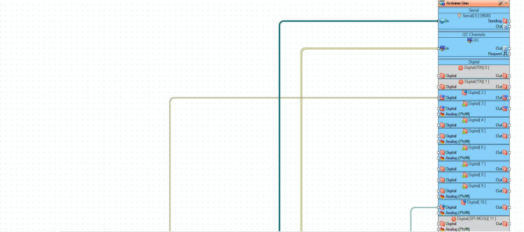
- Connect "RealTimeClock1" pin [I2C] to "Arduino" pin [I2C]
- Connect "HumidityThermometer1" pin [Sensor] to "Arduino" Digital pin [2]
- Connect "FormattedText1 " pin [Out] to "SDCard1" pin [In]
- Connect "SDCard1" pin [SPI] to "Arduino" pin [SPI]
- Connect "SDCard1" pin [Chip Select] to "Arduino" Digital pin [10]
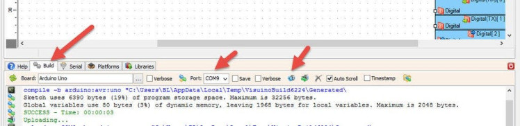
In Visuino, at the bottom click on the "Build" Tab, make sure the correct port is selected, then click on the "Compile/Build and Upload" button.
Step 9: PlayIf you power the Arduino module, The Data from the sensor DHT11 and time from the RTC module DS1307 will be saved every 10s to the SD card.
Congratulations! You have completed your project with Visuino. Also attached is the Visuino project, that I created for this tutorial, you can download it and open it in Visuino: https://www.visuino.eu
Schematics, diagrams and documents
Code
Credits
Related products


Leave your feedback...