
How To Make Usb To Ttl Converter (ch340)

About the project
let's build a USB to TTL converter
Project info
Difficulty: Moderate
Platforms: Arduino, NodeMCU, Raspberry Pi, Espressif, JLCPCB
Estimated time: 1 hour
License: Creative Commons Attribution-ShareAlike CC BY-SA version 4.0 or later (CC BY-SA 4+)
Items used in this project
Hardware components

Story
Hello there
To upload code to Arduino pro mini, esp12e or Atmel microcontrollers we need an external USB to serial or TTL converter. Lots of converters are available in the market for low prices like CP2102, F2232R, PL2303 and CH340. I just want to build my own converter. So I decided to make a USB to TTL converter. So in this tutorial, I am showing how I designed and made this cute USB to TTL converter. Let’s get started.
As always everything starts from the circuit and this is the circuit. So I designed the basic circuit diagram using easyeda.com I am using ch340 ic for this. I choose ch340ic because this ic is easy to solder and it has a 3.3.volt output. so we can program also with 3.3v logic ics
CIRCUIT DIAGRAM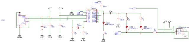
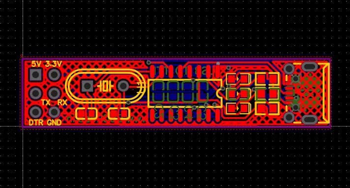
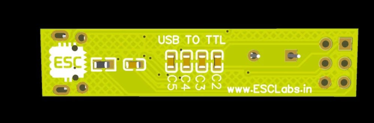
After designing the circuit I converted the circuit into PCB and then I arranged components and made the PCB. After designing our PCB looks like this.
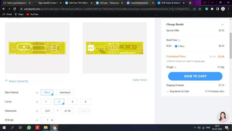
Next, I downloaded the Gerber files for PCB fabrication. To fabricate PCBs I went to jlcpcb.com You will get 5 awesome PCBs for just 2$ from JLCPCB and their PCB assembly starts from 0$.
Get JLCPCB $54 new user coupon: https://jlcpcb.com/ESC
To order click order now and upload your Gerber files. After uploading we can select quantity, thickness colour etc. Then you can place the order.
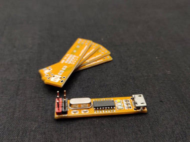
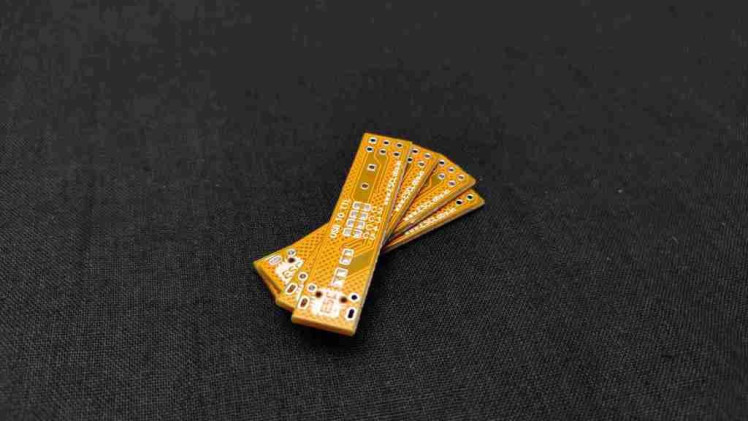
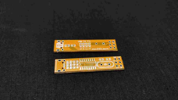
After 2 weeks I received the PCBs from JLCPCB. Here are the PCBs the PCB looks very cute and the quality is awesome.
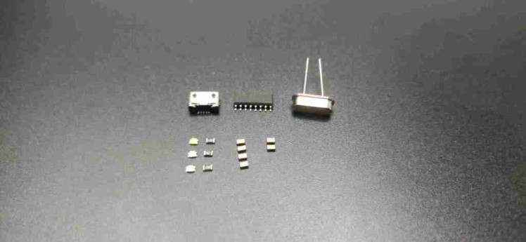
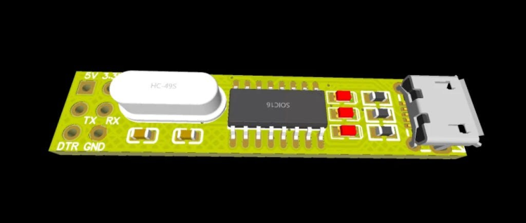
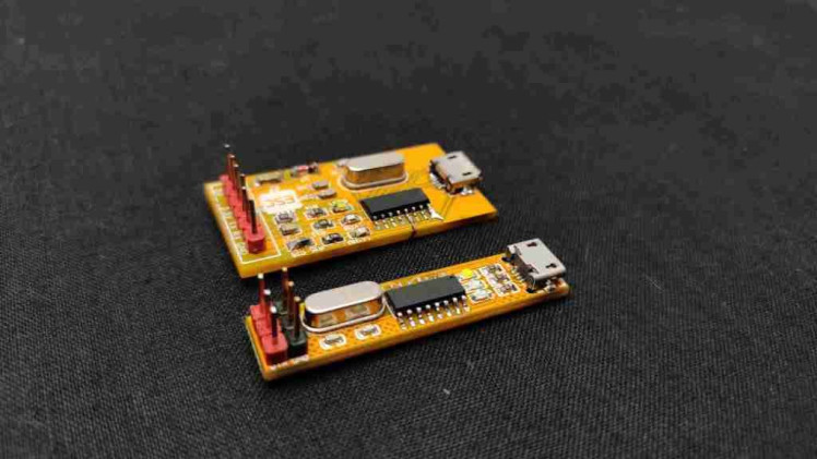
Now I grabbed ch340, crystal, micro USB port and other components. Here I am going with the reflow soldering method so first, I dispensed solder paste to the PCB pads after doing that I placed components. Now it’s time to reflow. So I placed the prepared PCB on my DIY hotplate and now see the process after reflow you can see the PCB cooking. Next, I placed other components and soldered them with my soldering iron. After finishing the soldering job our PCB look like this. See our new PCB is only having the half dimensions of the old PCB. Awesome right.?
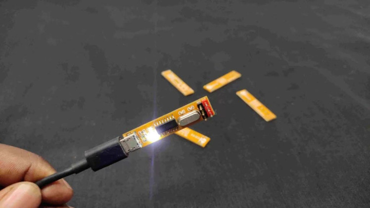
Now let’s connect a micro USB cable. And see the light. Now on the computer, you can see the computer detected our converter. Now let’s upload a sample code to this USB portless Arduino pro mini.So I connected wires to Arduino pro mini now I connected VCC to 5v ground to ground tx to RX RX to tx and DTR to DTR. after this connection in the Arduino IDE I opened the blynk example code and changed the blynk delay to 100 ms after that I selected the port and board and uploaded the code to pro mini now you can see the led of pro mini blinking perfectly. Our USB TO TTL CONVERTER worked without any problem.
So that’s all about today hope you enjoyed and learned something from my tutorial.
Schematics, diagrams and documents
Code
Credits
Related products


Leave your feedback...