
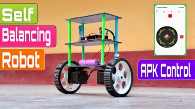
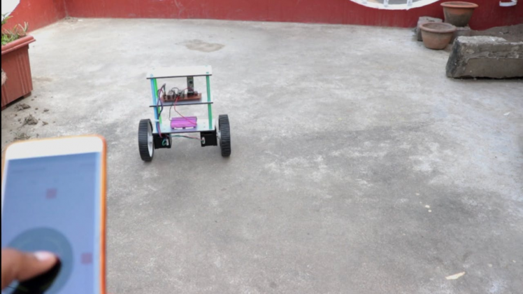
How To Make Diy Smartphones Controlled Self Balancing Robot

Made by rau7han / Artificial intelligence / Automotive / Retro Tech / Robotics / IoT
About the project
Hello Guys Whats up, In this instructable, i'll show you How to Make DIY Smartphones Controlled Self Balancing Robot. It's very interesting
Project info
Items used in this project

Story
Hello Guys
Whats up, In this blog i'll show you How to Make DIY Smartphones Controlled Self Balancing Robot. It's very interesting project for any electronics hobbyist & Engineers.
Self-balancing Robot is very interesting. Many friends around us were trying to make one, but they encounted a lot of chanllenges including the lack of the easy-to- assembly structures, the suitable electronic circuits and the programs.
So I decided to make a self-balancing robot as simple as possible.
I want the assembly of self-balancing robot to be very easy. It doesn’t need much wires, complicated connections and testing.
Thank You NextPCB:This project is successfully completed because of the help and support from NextPCB.
Guys if you have a PCB project, please visit their website and get exciting discounts and coupons.
Only 0$ for 5-10pcs PCB Prototypes:https://www.nextpcb.com
Register and get $100 from NextPCB: https://www.nextpcb.com/register
See more info about PCB Assembly Capabilities: https://www.nextpcb.com/register
Here are mid-summer sales at NextPCB :
1. Up to 30% off for the PCB orders
2. Up to 20% off for the PCBA orders
Visit my website DiY Projects Lab for More Projects I wish you liked it :)
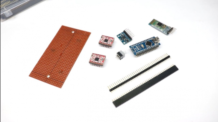
Here's the Full Video Tutorial Video Step 2: SuppliesParts and Materials Required
1 / 5

I bought most of these parts from Amazon but you can find them in any other electronics store as well.
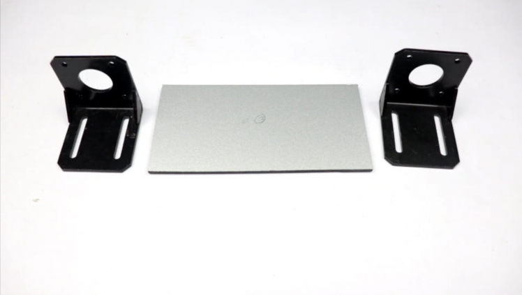
Nema 17 Stepper Motor Amazon IND / Amazon USA ,
L Mount Amazon IND / Amazon USA ,
Arduino nano Amazon IND / Amazon USA,
A4988 Driver Amazon IND / Amazon USA ,
MPU 6050 Amazon IND /Amazon USA ,
HC-05 Bluetooth Amazon IND / Amazon USA ,
Zero PCB
Female Header
Wheel
ACP Sheet, Pencil etc..
Apart from the above, you will need some cables, berg connectors and one on/off switch.
A Bit of Theory
Let's start with some fundamentals before getting our hands dirty.
The self-balancing robot is similar to an upside down pendulum.
Unlike a normal pendulum which keeps on swinging once given a nudge, this inverted pendulum cannot stay balanced on its own. It will simply fall over.
Then how do we balance it?
Consider balancing a broomstick on our index finger which is a classic example of balancing an inverted pendulum.
We move our finger in the direction in which the stick is falling. Similar is the case with a self-balancing robot, only that the robot will fall either forward or backward.
Just like how we balance a stick on our finger, we balance the robot by driving its wheels in the direction in which it is falling.
What we are trying to do here is to keep the center of gravity of the robot exactly above the pivot point.
To drive the motors we need some information on the state of the robot.
We need to know the direction in which the robot is falling, how much the robot has tilted and the speed with which it is falling.
All these information can be deduced from the readings obtained from MPU6050.
We combine all these inputs and generate a signal which drives the motors and keeps the robot balanced.
How Does It Work?
Self Balancing Robot is one such step which promotes that a robot should be able to have locomotion using the balancing capabilities just as the humans also possess.
This opens for the robots a plethora of task types which they can perform in the way humans do. The Self Balancing Robot Project consists of an Atmega328 microcontroller controlled system which with the help of its sensors mounted on the robot is able to balance the robot in upright posture.
If the robot is given a jerk in forward direction to tilt it in forward direction then it will oppose that force and try to be in the balanced position as it was. Similar is the thing for force from any direction on the robot, it will always try to remain balanced.
The robot also has excellent direction sense which helps it avoid any divergence of its course to another even if forced to do so.
The abilities of this robot is acheived with help of inputs from acceleromter and gyro sensors and outputs to the motor control section of the robot.
Let's Start Building
1 / 5
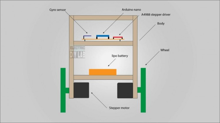
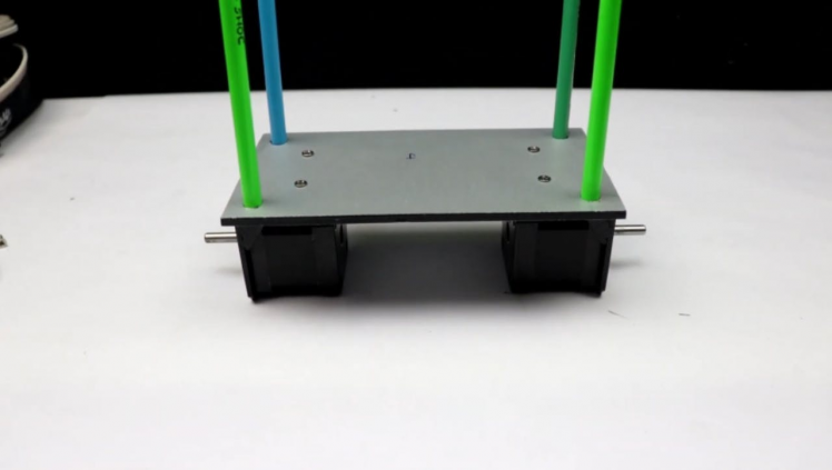
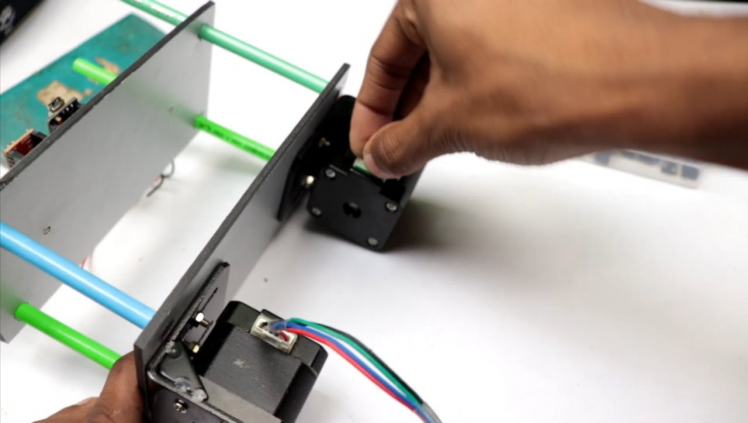
We will first complete the circuitry and structure of the robot
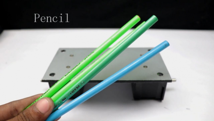
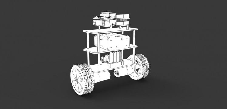
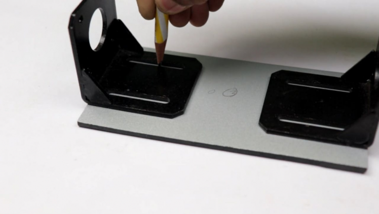
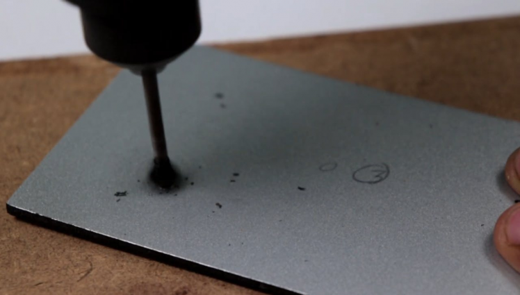
The robot is built on three layers of acrylic that are spaced 25mm apart using pencil.
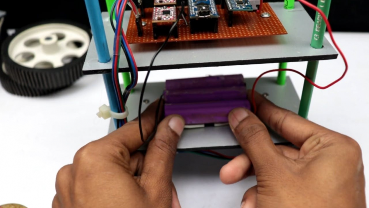
The bottom layer contains the two motors. The middle layer has the battery.
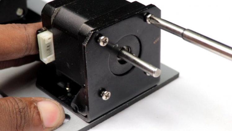
To make the whole structure strong enough, I use a 5mm thickness acrylic board to fix the two stepper motors.
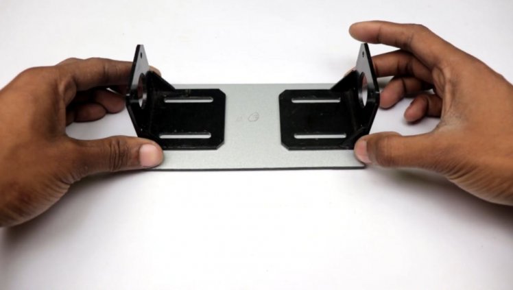
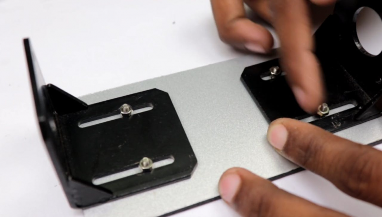
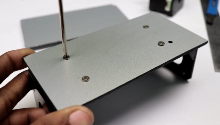
Attach Motor
1 / 3
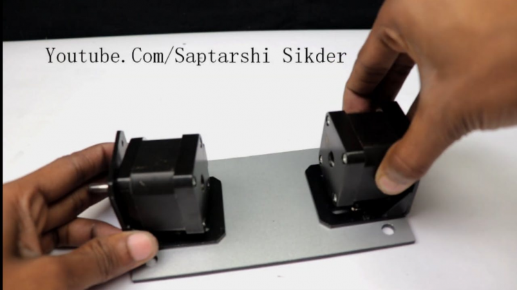

As you see the robot is built on three layers of acrylic sheet that are spaced 25mm apart using pencil. The bottom layer contains the two motors.
The assembling is pretty straight forward; use nuts and bolts to secure the motor and boards in place.After assembling it should look something like this shown in the picture above
Measuring Angle of Inclination Using Gyroscope
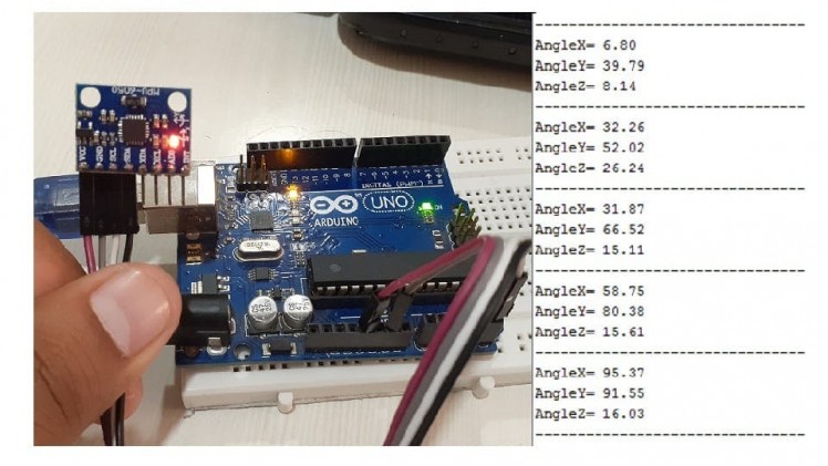
The 3-axis gyroscope of MPU6050 measures angular rate (rotational velocity) along the three axes. For our self-balancing robot, the angular velocity along the x-axis alone is sufficient to measure the rate of fall of the robot.
In the code given below, we read the gyro value about the x-axis, convert it to degrees per second and then multiply it with the loop time to obtain the change in angle. We add this to the previous angle to obtain the current angle.
#include "Wire.h"
#include "I2Cdev.h"<br>#include "MPU6050.h"
 MPU6050 mpu;
 int16_t gyroX, gyroRate;
 float gyroAngle=0;
 unsigned long currTime, prevTime=0, loopTime;
void setup()
{
mpu.initialize();
Serial.begin(9600);
}
void loop()
{   currTime = millis();
 loopTime = currTime - prevTime;
prevTime = currTime;
gyroX = mpu.getRotationX();
gyroRate = map(gyroX, -32768, 32767, -250, 250);
gyroAngle = gyroAngle + (float)gyroRate*loopTime/1000;
 Serial.println(gyroAngle);
 }
The position of the MPU6050 when the program starts running is the zero inclination point. The angle of inclination will be measured with respect to this point. Keep the robot steady at a fixed angle and you will observe that the angle will gradually increase or decrease.
It won't stay steady. This is due to the drift which is inherent to the gyroscope in the code given above, loop time is calculated using the millis() function which is built into the Arduino IDE. In later steps, we will be using timer interrupts to create precise sampling intervals.
This sampling period will also be used in generating the output using a PID controller
Circuit Diagram
1 / 2
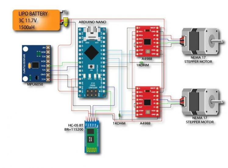
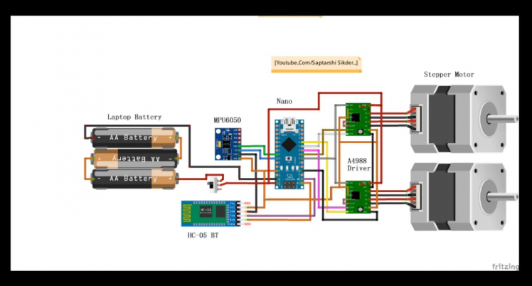
The circuit diagram for this project is not hard.
Pinout for Arduino nano (atmega328p):
- A0 - V_BATPIN: after the resistor divisor we should get [0V;5V]->[0;1023] on analogue V_BATPIN with R1=33k and R2=51k, i.e. (+12v)51k(A0 pin)33k(GND)
- A2 - BUZZERPIN
I2C:
- A4 - SDA
- A5 - SCL
RC control:
- D2 - CPPM (PPM_SUM)
Motor driver pins:
- D5 - STEP1 (PORTD 5)
- D6 - STEP2 (PORTD 6)
- D7 - DIR1 (PORTD 7)
- D8 - DIR2 (PORTB 0)
- D4 - ENABLE (for both)
If you look to the tail of the robot:
- right motor = STEP1 & DIR1
- left motor = STEP2 & DIR2
1 / 5
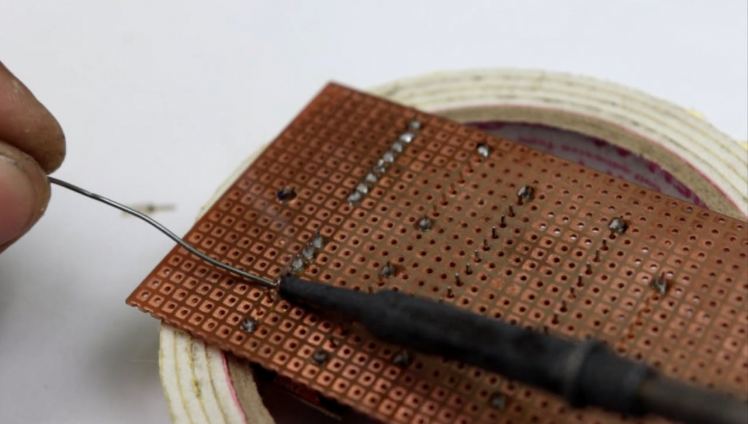
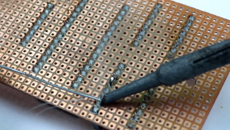
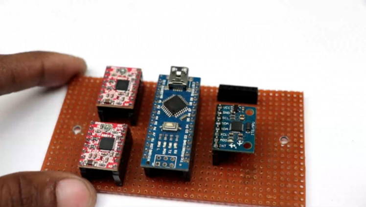
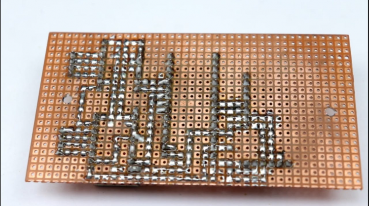
Before jump to make the final board, test the circuit on a breadboard first. If the circuit works perfectly on the breadboard, then move to solder the components on the prototype board.
I used the zero prototype PCB board. Mounting the Nano: First cut two rows of female header pin with 15 pins in each.
I used a diagonal nipper to cut the headers. Then solder the header pins. Be sure the distance between the two rails fits the Arduino nano.
Mounting A4988: Cut a female header. Then solder it as shown in the picture.
Mounting the terminals and components: Solder the remaining components as shown in pictures.
Wiring: Make the wiring as per the schematic.
Connect Motor Wire With Arduino Board
1 / 3
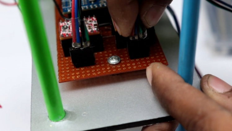
First connect both motor with motor Driver as show in Circuit diagram, then connect bluetooth module and battery
Software & Libraries
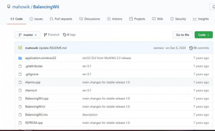
First, download the attached Arduino Code. Then download the following libraries and install them.
Libraries: Download and install the following libraries:
https://github.com/mahowik/BalancingWii
In the code, you have to change the following two things.
Also see for new defines added with this project for robot setup:<br>#define CURRENT_AXIS PITCH // possible to choose ROLL or PITCH axis as current.
//#define INVERT_CURRENT_AXIS // invert current axis sign, i.e. instead of turning sensor board
//#define REVERSE_MOTORS_DIRECTION // reverse both motors direction
#define MAX_SPEED 400 // should be <= 500 #define MAX_TARGET_ANGLE 120 // where 10 = 1 degree, should be <= 15 degree (i.e. <= 150) #define MAX_STEERING 90 // should be <= 100
//#define GY_521_INVERTED_BY_Z // Chinese 6 DOF with MPU6050, LLC, inverted/reversed by Z
1 / 2
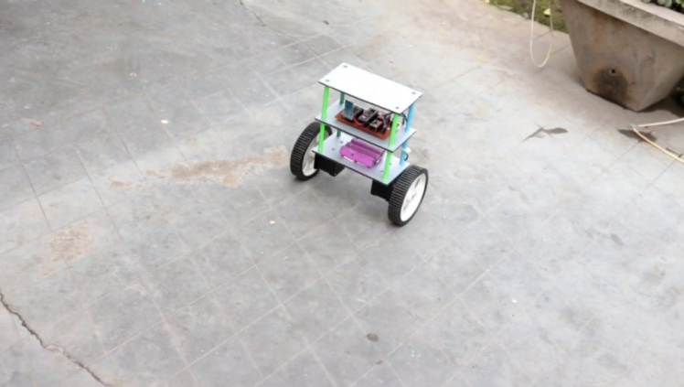
Spending a bit more time on tweaking the PID constants would give us a better result. The size of our robot also limits the level of stability we can achieve.
It is easier to build a full-sized balancing robot.
I guess, our robot does a pretty decent job in balancing on various surfaces as shown in the video.
That's it for now.
Thanks for your time. Don't forget to leave your thoughts in the comments section.
Schematics, diagrams and documents
Code
Credits
Related products


Leave your feedback...