
How To Make Diy Esp32 Cam Surveillance Robot

Made by raushan-kumar / Automotive / Robotics / Wearables / IoT
About the project
The DIY ESP32 Cam Surveillance Car is a great way to get started with building your own surveillance car. This project uses the ESP32 camera
Project info
Difficulty: Moderate
Estimated time: 1 hour
Items used in this project
Hardware components

Story
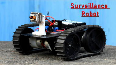
The DIY ESP32 Cam Surveillance Car is a great way to get started with building your own surveillance car. This project uses the ESP32 camera module to create a low-cost, low-power, and high-quality surveillance car. The project is perfect for anyone who wants to get started with building their own surveillance car, or for anyone who wants to add an extra layer of security to their home or business.
DIY ESP32 Cam Surveillance Car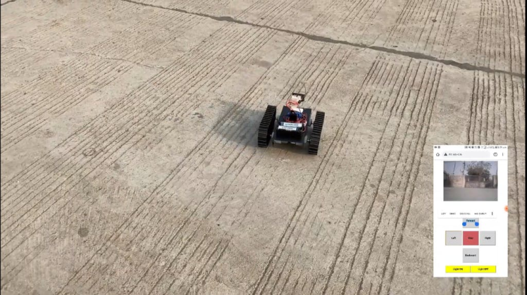
There are many reasons why you might want to consider adding a There are many reasons why you might want to consider adding a DIY ESP32 Cam Surveillance Car to your vehicle. One reason is that it can help you keep an eye on your surroundings while you're driving.
This can be especially useful if you're driving in a high-crime area or if you're worried about being followed. Another reason is that it can be a fun and easy project to do with your friends or family in your vehicle. One reason is that it can help you keep an eye on your surroundings while driving.
This can be especially useful if you're going to a high-crime area or are worried about being followed. Another reason is that it can be a fun and easy project to do with your friends or family
Supplies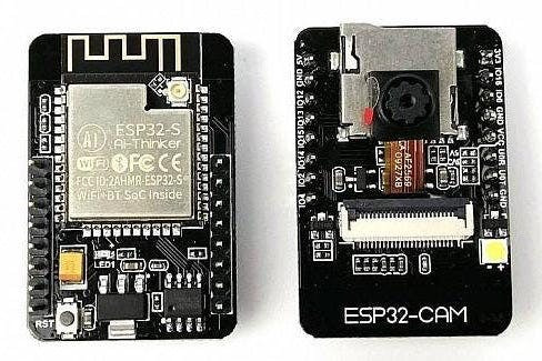
Part of List-
- ESP32 Cam
- Dc Gear Motor 4x
- Wheel 4x
- L298N Motor Driver
- 18650 Battery
- FTDI Programmer cable
- jumper wire
1 / 3
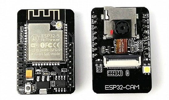

The ESP32-CAM is a tiny camera module with the ESP32-S chip that costs less than $10. The ESP32-CAM can be used in various IoT applications. The ESP32-CAM can be used to take high-quality still images and videos. The ESP32-CAM can also be used as a security camera.
The ESP32-CAM is ideal for low-power applications such as security cameras, drones, and industrial IoT applications. The ESP32-CAM can be powered from 5V or 3.3V and features a built-in USB-serial converter for programming and debugging.
The ESP32-CAM is ideal for security cameras, drones, and industrial IoT applications.
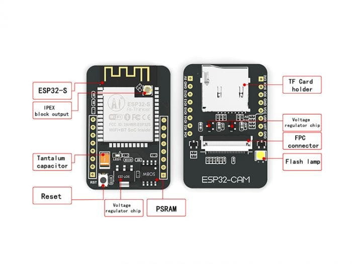
ESP32-CAMFeatures
- Onboard ESP32-S module, sustains WiFi + Bluetooth
- OV2640 camera with flash
- Onboard TF card slot, supports up to 4G TF cards for data storage
- Supports WiFi video monitoring and WiFi image upload
- Supports multi sleep modes, deep sleep current as low as 6mA
- The control interface is accessible via pin header, easy to be integrated and embedded into user products
ESP32-CAMApplications
This board can help us in developing projects that can see, and some impressive applications are:
The ESP32-CAM suit for IoT applications such as:
- Intelligent home appliances image upload
- Wireless monitoring
- Smart agriculture
- QR wireless tag
- facial recognition
- Security Camera.
- Longs Time Lapse Shots.
- 3D Printer Monitoring Camera.
- Doorbell camera.
- Etc.
1 / 2
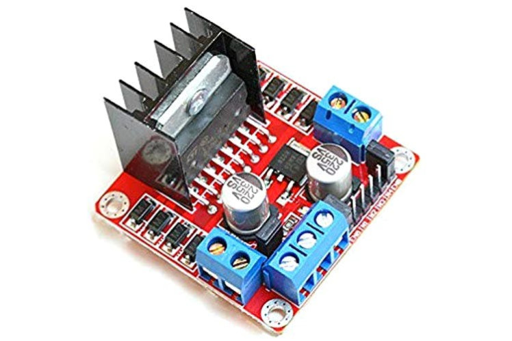

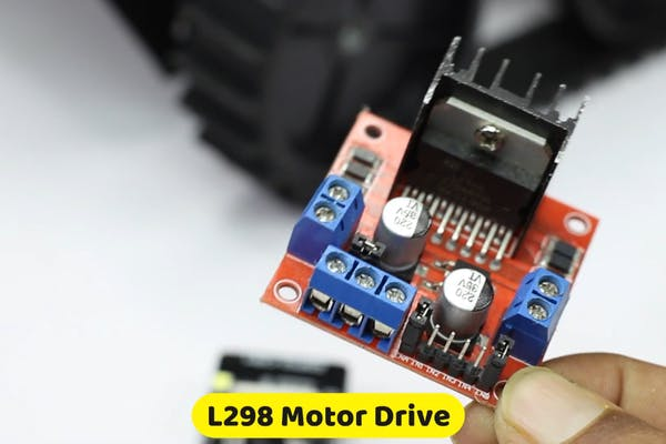
An L298 module is a dual H-bridge driver module that is typically used for controlling motors. It is also used for other purposes such as voltage regulation and DC to DC conversion.
The module has two H-bridges that can be used to control the speed and direction of DC motors. The module can also be used to control the voltage and current of AC motors. The module is typically used for controlling motors
Schematics Diagram1 / 2
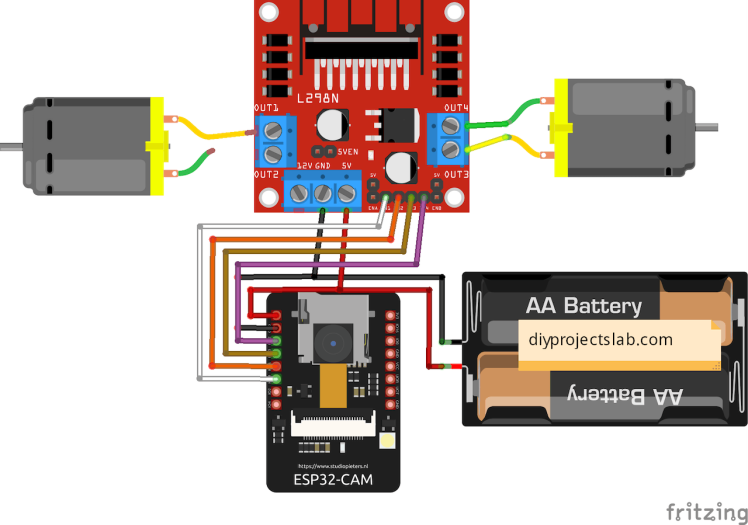
Now for powering the car we will use a 12v Li-ion battery, and connect accordingly
+Ve of battery to ---- +12 of L298N
-Ve of battery to ----- GND of L298N
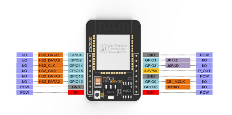
For powering up the ESP32-CAM module we will use L298N's +5v as a source to do this Place the power jumper which is left on board.
connect :
L298N
+5 -------- 5v of ESP-32 CAM
GND -------- GND of ESP-32 CAM
IN1 --------- GPIO 14 of ESP-32 CAM
IN2 ---------- GPIO15 of ESP-32 CAM
IN3 ---------- GPIO13 of ESP-32 CAM
IN4 ----------- GPIO12 of ESP-32 CAM
since we are not going to control the speed of the car and will run at max speed place the ENA and ENB jumpers in place.
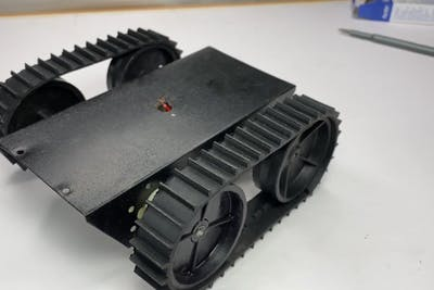
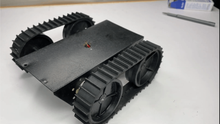
Assembling the Chassis
Before making chassis and setting motors, solder wires to Motors.
we carry used here a ready-made chassis which is easily available on the market, by the way, you can use any cardboard or easy plyboard cutout as chassis.
Sample Hardware Installation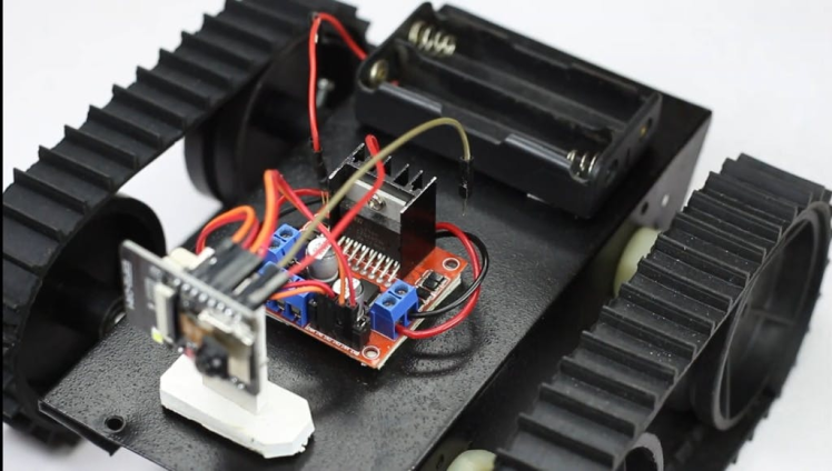
The diagram shows the hardware connection between Motor Driver Module and. Besides ESP32 cam, it may interface with any microcontroller such as PIC and etc.
Note: The Ground of the battery, Motor Driver Module and Arduino should be connected together.
The connection between: To see the result, download the sample source code in ESP32
1 / 3
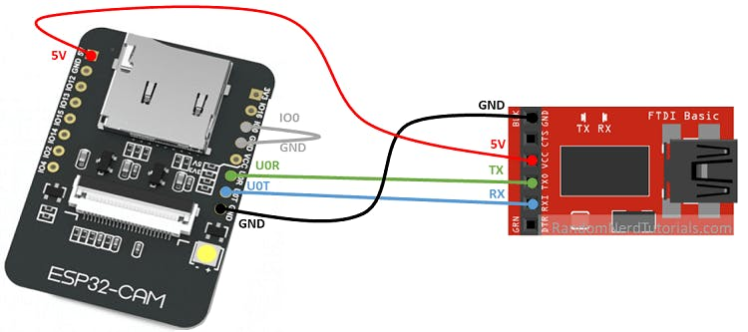
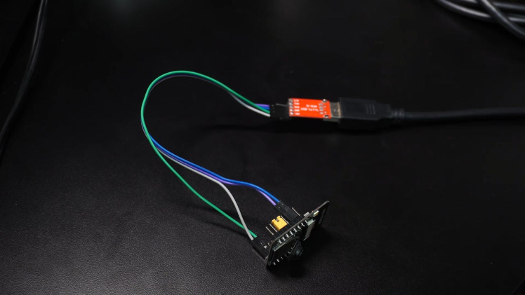
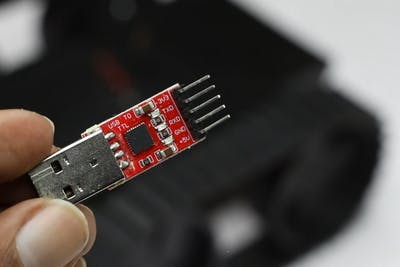
Plug in the camera to the connector of the ESP32-CAM board.
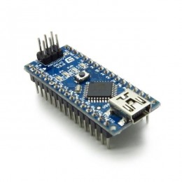
Programming of ESP32-CAM is done via CP2102 USB to TTL UART serial converter Module. First, connect the USB to the TTL module with ESP32-CAM and short IOO pin of ESP32-CAM to GND according to the above diagram.
open the files menu in Arduino IDE. and then open preference and paste the link in additional boards managers URL and press
Upload Source code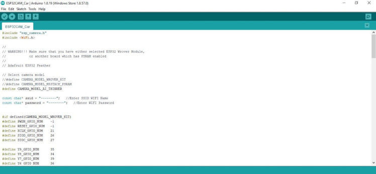
- Select the Board "Ai thinker ESP32-CAM"
- In the sketch uncomment the model of the ESP32 CAM you are using.
- Put in the WiFi credentials and Upload.
- Once the ESP32 is burned.
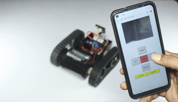
- Disconnect the GPIO0-GND jumper and reset the board, look at the IP printed on the Serial Monitor.
#include "esp_camera.h"
#include <WiFi.h>

//
// WARNING!!! Make sure that you have either selected ESP32 Wrover Module,
//            or another board which has PSRAM enabled
//
// Adafruit ESP32 Feather
// Select camera model
//#define CAMERA_MODEL_WROVER_KIT
//#define CAMERA_MODEL_M5STACK_PSRAM
#define CAMERA_MODEL_AI_THINKER

const char* ssid = "--------";   //Enter SSID WIFI Name
const char* password = "--------";   //Enter WIFI Password

#if defined(CAMERA_MODEL_WROVER_KIT)
#define PWDN_GPIO_NUM    -1
#define RESET_GPIO_NUM   -1
#define XCLK_GPIO_NUM    21
#define SIOD_GPIO_NUM    26
#define SIOC_GPIO_NUM    27

#define Y9_GPIO_NUM      35
#define Y8_GPIO_NUM      34
#define Y7_GPIO_NUM      39
#define Y6_GPIO_NUM      36
#define Y5_GPIO_NUM      19
#define Y4_GPIO_NUM      18
#define Y3_GPIO_NUM       5
#define Y2_GPIO_NUM       4
#define VSYNC_GPIO_NUM   25
#define HREF_GPIO_NUM    23
#define PCLK_GPIO_NUM    22


#elif defined(CAMERA_MODEL_AI_THINKER)
#define PWDN_GPIO_NUM     32
#define RESET_GPIO_NUM    -1
#define XCLK_GPIO_NUM      0
#define SIOD_GPIO_NUM     26
#define SIOC_GPIO_NUM     27


#define Y9_GPIO_NUM       35
#define Y8_GPIO_NUM       34
#define Y7_GPIO_NUM       39
#define Y6_GPIO_NUM       36
#define Y5_GPIO_NUM       21
#define Y4_GPIO_NUM       19
#define Y3_GPIO_NUM       18
#define Y2_GPIO_NUM        5
#define VSYNC_GPIO_NUM    25
#define HREF_GPIO_NUM     23
#define PCLK_GPIO_NUM     22

#else
#error "Camera model not selected"
#endif

// GPIO Setting
extern int gpLb =  2; // Left 1
extern int gpLf = 14; // Left 2
extern int gpRb = 15; // Right 1
extern int gpRf = 13; // Right 2
extern int gpLed =  4; // Light
extern String WiFiAddr ="";

void startCameraServer();

void setup() {
  Serial.begin(115200);
  Serial.setDebugOutput(true);
  Serial.println();

  pinMode(gpLb, OUTPUT); //Left Backward
  pinMode(gpLf, OUTPUT); //Left Forward
  pinMode(gpRb, OUTPUT); //Right Forward
  pinMode(gpRf, OUTPUT); //Right Backward
  pinMode(gpLed, OUTPUT); //Light

  //initialize
  digitalWrite(gpLb, LOW);
  digitalWrite(gpLf, LOW);
  digitalWrite(gpRb, LOW);
  digitalWrite(gpRf, LOW);
  digitalWrite(gpLed, LOW);

  camera_config_t config;
  config.ledc_channel = LEDC_CHANNEL_0;
  config.ledc_timer = LEDC_TIMER_0;
  config.pin_d0 = Y2_GPIO_NUM;
  config.pin_d1 = Y3_GPIO_NUM;
  config.pin_d2 = Y4_GPIO_NUM;
  config.pin_d3 = Y5_GPIO_NUM;
  config.pin_d4 = Y6_GPIO_NUM;
  config.pin_d5 = Y7_GPIO_NUM;
  config.pin_d6 = Y8_GPIO_NUM;
  config.pin_d7 = Y9_GPIO_NUM;
  config.pin_xclk = XCLK_GPIO_NUM;
  config.pin_pclk = PCLK_GPIO_NUM;
  config.pin_vsync = VSYNC_GPIO_NUM;
  config.pin_href = HREF_GPIO_NUM;
  config.pin_sscb_sda = SIOD_GPIO_NUM;
  config.pin_sscb_scl = SIOC_GPIO_NUM;
  config.pin_pwdn = PWDN_GPIO_NUM;
  config.pin_reset = RESET_GPIO_NUM;
  config.xclk_freq_hz = 20000000;
  config.pixel_format = PIXFORMAT_JPEG;
  //init with high specs to pre-allocate larger buffers
  if(psramFound()){
    config.frame_size = FRAMESIZE_UXGA;
    config.jpeg_quality = 10;
    config.fb_count = 2;
  } else {
    config.frame_size = FRAMESIZE_SVGA;
    config.jpeg_quality = 12;
    config.fb_count = 1;
  }


  // camera init
  esp_err_t err = esp_camera_init(&config);
  if (err != ESP_OK) {
    Serial.printf("Camera init failed with error 0x%x", err);
    return;
  }


  //drop down frame size for higher initial frame rate
  sensor_t * s = esp_camera_sensor_get();
  s->set_framesize(s, FRAMESIZE_CIF);


  WiFi.begin(ssid, password);


  while (WiFi.status() != WL_CONNECTED) {
    delay(500);
    Serial.print(".");
  }
  Serial.println("");
  Serial.println("WiFi connected");


  startCameraServer();


  Serial.print("Camera Ready! Use 'http://");
  Serial.print(WiFi.localIP());
  WiFiAddr = WiFi.localIP().toString();
  Serial.println("' to connect");
}


void loop() {
  // put your main code here, to run repeatedly:

}
DOWNLOAD THE CODE Click Here.
Test It and Enjoy It
Schematics, diagrams and documents
Code
Credits
Related products


Leave your feedback...