
How To Control Pwm Signal Generator Module Using Visuino

Made by Ron / Communication / Lights / Notifications / Sensors / IoT
About the project
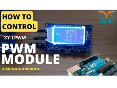
In this tutorial we will explore how to control a PWM Signal Generator Module XY-LPWM using Arduino and Visuino. Watch the Video!
Project info
Difficulty: Easy
Estimated time: 1 hour
License: GNU General Public License, version 3 or later (GPL3+)
Items used in this project
Hardware components

Story
In the first part we will set the Frequency & Duty Cycle using the serial monitor and in the second part we will make a project where the Arduino will change the Frequency every 2s and Duty Cycle every 1s. The purpose of this tutorial is to show how simple it is to control the PWM module and you will also learn how to use the "Serial Software" component in Visuino.
Step 1: What You Will Need1 / 4
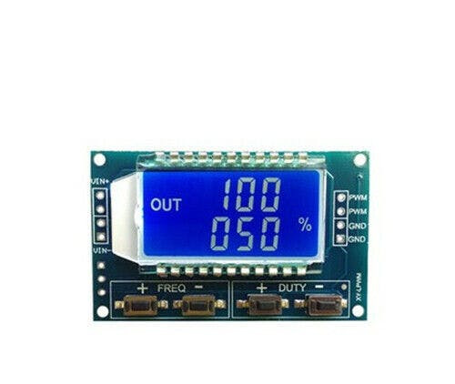

- XY-LPWM or HW-753 PWM Signal Generator Module
- Arduino UNO (or any other Arduino)
- Jumper wires
- Visuino program: Download Visuino
- Operating Voltage: 3.3 to 30 Volts
- Frequency Range: 1 Hz to 150 kHz
- 0-100% duty cycle
- Frequency Accuracy: Approximately 2% accuracy within each range
- Signal Load Capacity: Output current ranging from 5 to 30 mA
- Output Amplitude: PWM amplitude matches the supply voltage
- Operating Temperature Range: -20 to +70 degrees Celsius
- Communication Standard: 9600 bps Data bits: 8
- PWM Frequency Configuration:
- "F101": Sets the frequency to 101 Hz (range: 001 ~ 999)
- "F1.05": Sets the frequency to 1.05 kHz (range: 1.00 ~ 9.99)
- "F10.5": Sets the frequency to 10.5 kHz (range: 10.0 ~ 99.9)
- "F1.0.5": Sets the frequency to 105 kHz (range: 1.0.0 ~ 1.5.0)
- Successful retrieval returns: "DOWN."
- If retrieval fails, the response is: "FALL."
- PWM Duty Cycle Configuration:
- "DXXX": Sets the PWM duty cycle to XXX (range: 001 ~ 100)
- For example, "D050" sets the PWM duty cycle to 50%.
- Parameter Retrieval:
- To read the configured parameters, send the "read" string.
- The result will be for example: F5.00 D060
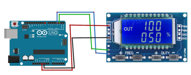
- Connect Arduino Digital pin [2] to the PWM Module pin [TX]
- Connect Arduino Digital pin [3] to the PWM Module pin [RX]
- Connect Arduino pin [5V] to the PWM Module pin [VIN+]
- Connect Arduino pin [GND] to the PWM Module pin [VIN-]
1 / 2
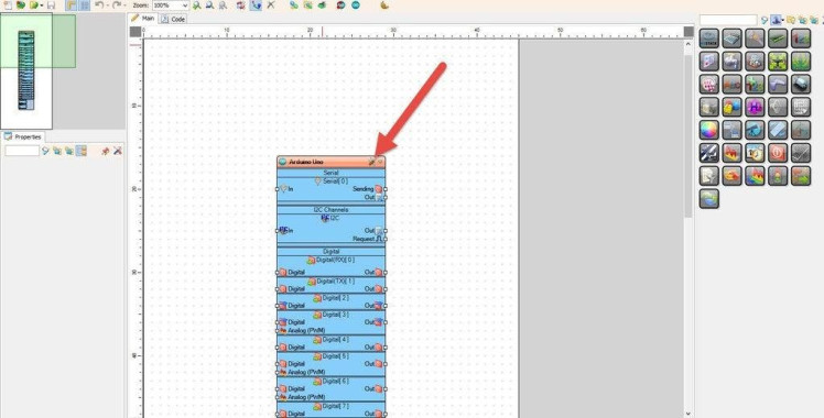
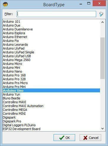
Start Visuino as shown in the first picture Click on the "Tools" button on the Arduino component (Picture 1) in Visuino When the dialog appears, select "Arduino UNO" as shown on Picture 2
Step 6: About the Visuino "Software Serial Port" Component1 / 2

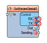
We can use the "Software Serial Port" component to implement a Software simulated Serial port. So if we want to use some other pins on the Arduino for the RX and TX we can add this component and connect it to other digital pins and we will create a new serial connection.
Step 7: Sending Commands to the Module Using Serial Monitor1 / 5
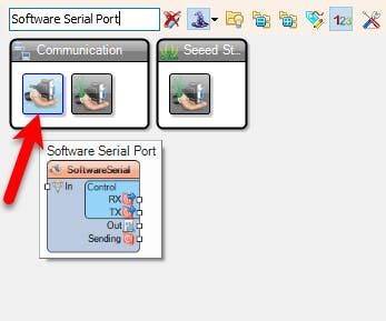
- Add "Software Serial Port" component
- Connect Arduino Serial pin [Out] to "SoftwareSerial1" pin [In]
- Connect "SoftwareSerial1" pin [RX] to Arduino Digital pin [2]
- Connect "SoftwareSerial1" pin [TX] to Arduino Digital pin [3]
- Connect "SoftwareSerial1" pin [Out] to Arduino Serial pin [In]
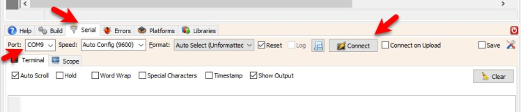
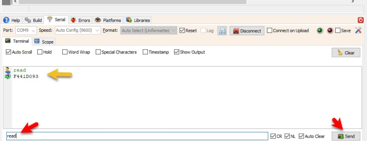
Upload the project (see the step Generate, Compile, And Upload The Arduino Code) and in Visuino select "Serial" tab, select the Port and click "Connect" button.
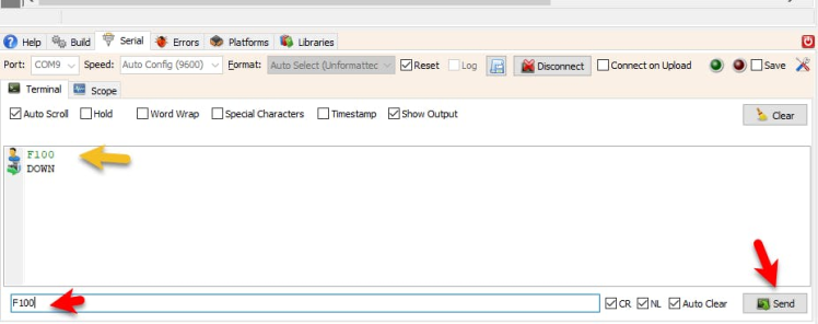
- Once connected you can start sending commands to the module by typing for example: F100
- This will set the module to 100hz frequency
- If the module accepted the command, you will get a response "DOWN" if not you will see a response "FALL"
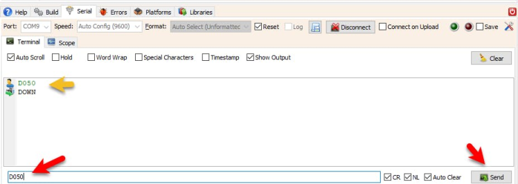
- and if you type D050 and press Enter it will set the module Duty Cycle to 50%
- To get the current Frequency and Duty Cycle from the module you can send the command: read
- and you will get for example F441D093 meaning that the current Frequency is 441Hz and the Duty Cycle is 93%
1 / 4
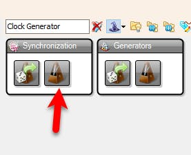
For this experiment we will Add 2X "Clock Generator" component, with one we will change the frequency and with the other we will change the Duty Cycle.
- Add 2X "Clock Generator" component
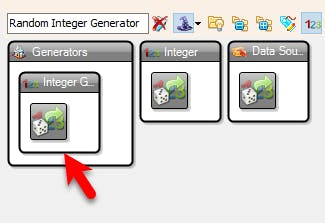
- Add 2X "Random Integer Generator" component
With First Random Integer Generator we will randomly generate a Frequency from 1 to 1000 and with the second Random Integer Generator we will set randomly generate a Duty Cycle from 10 to 99
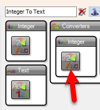
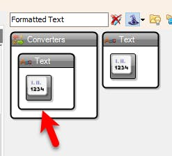
- Add 2X "Integer To Text" component
This component will change the Integer value from the Random Integer Generator to a text that we will use to form a command for the module.
- Add 2X "Formatted Text" component
With the "Formatted Text" component we will form the commands from the text values
- Add "Software Serial Port" component
1 / 7


- Select "ClockGenerator1" and in the properties window set "Frequency" to 0.5
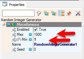
- Select "RandomIntegerGenerator1" and in the properties window set "Min" to 1 and "Max" to 1000
- Select "RandomIntegerGenerator2" and in the properties window set "Min" to 10 and "Max" to 99
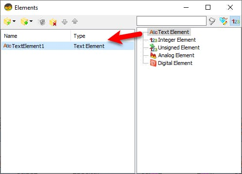
- Double click on the "RandomIntegerGenerator1" and in the "Elements" window drag "Text Element" to the left side and close the "Elements" window
- Double click on the "RandomIntegerGenerator2" and in the "Elements" window drag "Text Element" to the left side and close the "Elements" window
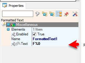
- Select "FormattedText1" and in the properties window set "Text" to F%0
This means that the Output will be F and %0 represents the value from "Text Element1"
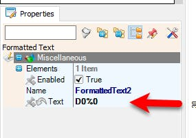
- Select "FormattedText2" and in the properties window set "Text" to D0%0
This means that the Output will be D0 and %0 represents the value from "Text Element1"
Step 10: Connect the Components1 / 2
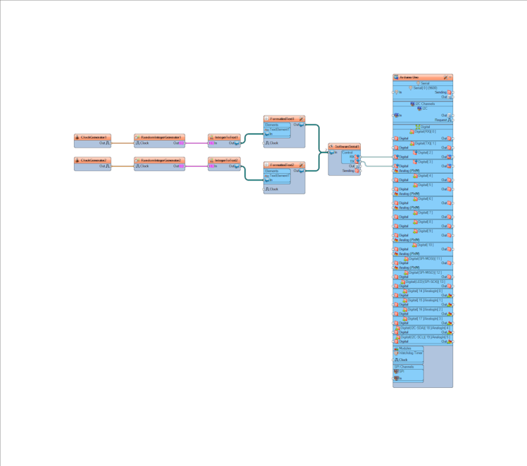
- Connect "ClockGenerator1" pin [Out] to "RandomIntegerGenerator1" pin [Clock]
- Connect "ClockGenerator2" pin [Out] to "RandomIntegerGenerator2" pin [Clock]
- Connect "RandomIntegerGenerator1" pin [Out] to "IntegerToText1" pin [In]
- Connect "RandomIntegerGenerator2" pin [Out] to "IntegerToText2" pin [In]
- Connect "IntegerToText1" pin [Out] to "FormattedText1" > "Text Element1" pin [In]
- Connect "IntegerToText2" pin [Out] to "FormattedText2" > "Text Element1" pin [In]
- Connect "FormattedText1" pin [Out] to "SoftwareSerial1" pin [In]
- Connect "FormattedText2" pin [Out] to "SoftwareSerial1" pin [In]
- Connect "SoftwareSerial1" pin [RX] to Arduino Digital pin [2]
- Connect "SoftwareSerial1" pin [TX] to Arduino Digital pin [3]
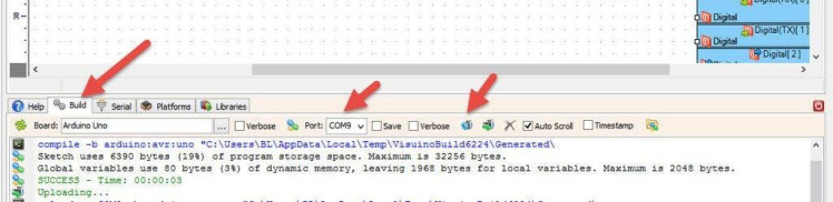
In Visuino, at the bottom click on the "Build" Tab, make sure the correct port is selected, then click on the "Compile/Build and Upload" button.
Step 13: Extra Tips1 / 2


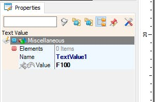
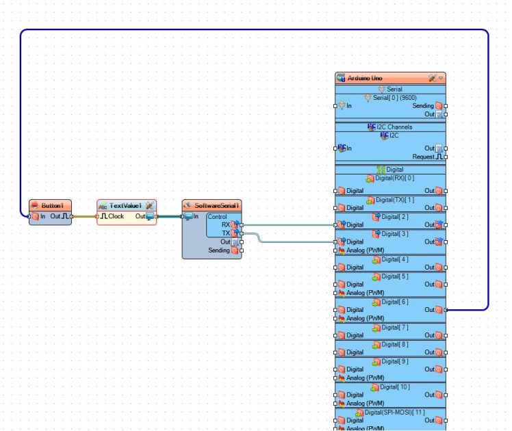
To set the Default Frequency or Duty Cycle, you could for example add "Text Value" component and in the properties window set "Value" to F100
Then Add "Debounce button" component and connect some Arduino digital pin to it.
Now If you will press the button the Signal will trigger the Text Value component to send the command to the module.
Schematics, diagrams and documents
Code
Credits
Related products


Leave your feedback...