
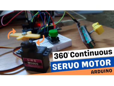
How To Control A 360 Continuous Servo Motor Using Arduino

Made by Ron / Automotive / Home Automation / Robotics / Sensors
About the project
In this tutorial we are going to learn how to control the speed and direction of a Continuous Rotation Servo using a potentiometer & button
Project info
Difficulty: Easy
Platforms: Arduino, DFRobot, Visuino
Estimated time: 1 hour
License: GNU General Public License, version 3 or later (GPL3+)
Items used in this project
Hardware components

Story
Also check out this great Video on How Continuous Rotation Servo Works
Step 1: What You Will Need1 / 7
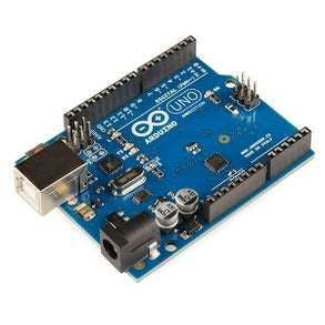
- Arduino UNO (Or any other Arduino)
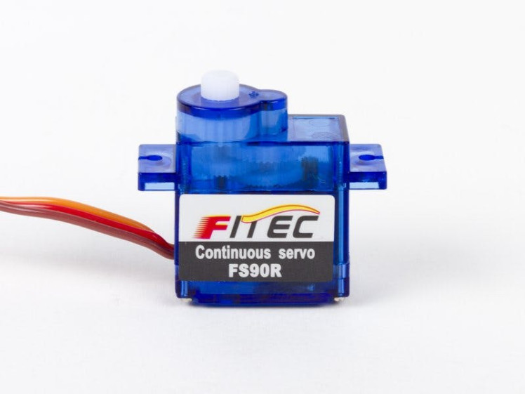
- 360 Continuous Rotation SERVO Motor
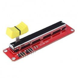
- Potentiometer module
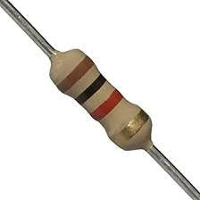
- 1k ohm Resistor
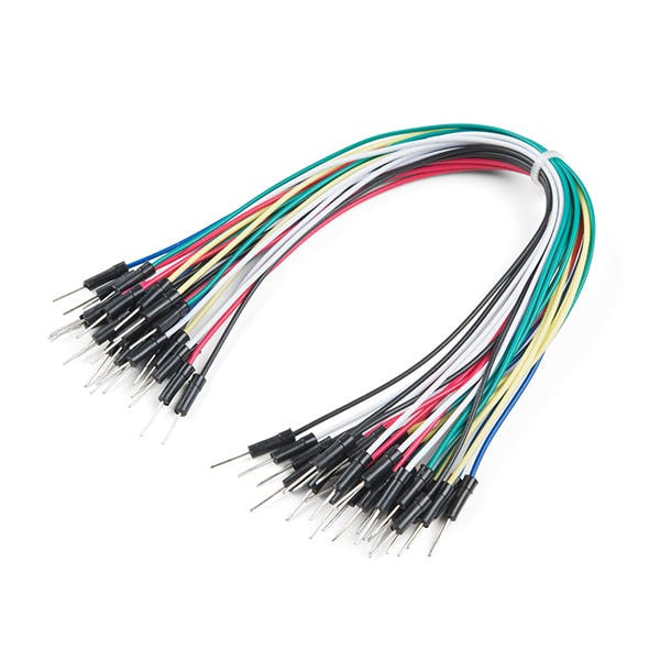
- Jumper wires
- Breadboard
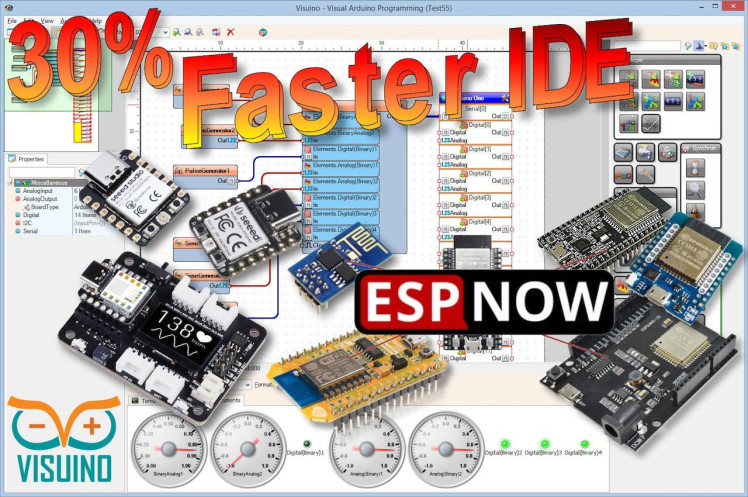
- Visuino program: Download Visuino

Thank you PCBWay for supporting this tutorial and helping users learn more about electronics.
What I like about the PCBWay is that you can get 10 boards for approximately $5 which is really cost effective for professional made boards, not to mention how much time you save!
Go check them out here. They also offer a lot of other stuff in case you might need it like assembly, 3D printing, CNC machining and a lot more.
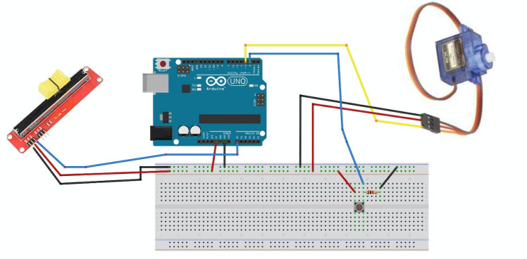
- Connect Arduino pin [5V] to Driver Board pin [VCC]
- Connect Arduino pin [GND] to Driver Board pin [GND]
- Connect Arduino pin [5V] to breadboard positive pin [Red line]
- Connect Arduino pin [GND] to breadboard negative pin [Black line]
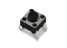
- Connect Arduino Digital pin [2] to the Resistor and button
- Connect other side of the resistor to the breadboard pin [GND]
- Connect Other pin of the button to the breadboard positive pin [5V]
- Connect potentiometer pin [DTA] to arduino analog pin [A0]
- Connect potentiometer pin [VCC] to the breadboard positive pin [5V]
- Connect potentiometer pin [GND] to the breadboard pin [GND]
- Connect Servo motor "Orange" (signal) pin to Arduino Digital pin[3]
- Connect Servo motor "Red" pin to Arduino positive pin[5V]
- Connect Servo motor "Brown" pin to Arduino negative pin[GND]
1 / 2
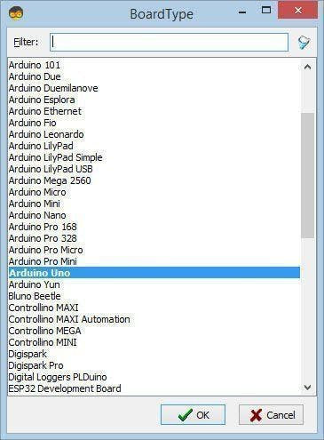
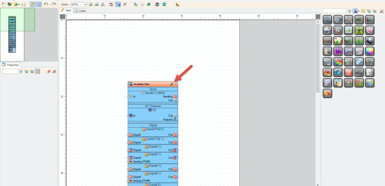
Start Visuino as shown in the first picture Click on the "Tools" button on the Arduino component (Picture 1) in Visuino When the dialog appears, select "Arduino UNO" as shown on Picture 2
Step 5: In Visuino Add Components1 / 4

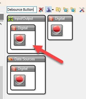
- Add "Debounce Button" component
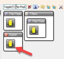
- Add "Toggle(T) Flip-Flop" component
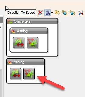
- Add "Speed and Direction To Speed" component
- Add "Servo" component
1 / 2
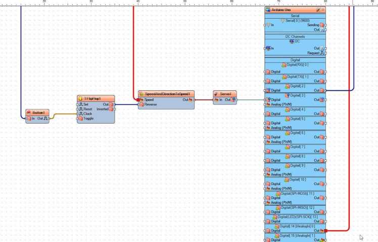
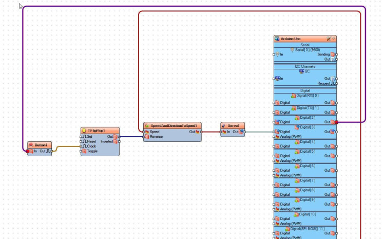
- Connect Arduino digital pin [2] to "Button1" pin[In]
- Connect "Button1" pin[Out] to "TFlipFlop1" pin [Clock]
- Connect "TFlipFlop1" pin [Out] to "SpeedAndDirectionToSpeed1" pin [Reverse]
- Connect Arduino analog pin [0] to "SpeedAndDirectionToSpeed1" pin [Speed]
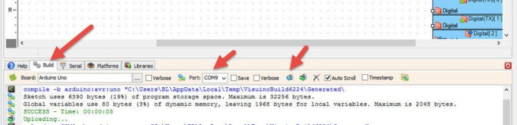
In Visuino, at the bottom click on the "Build" Tab, make sure the correct port is selected, then click on the "Compile/Build and Upload" button.
Step 8: PlayIf you power the Arduino Uno module, the Servo motor is ready to spin.
By sliding potentiometer you can regulate the motor speed and change the direction by pushing the button. Congratulations! You have completed your Project. Also attached is the Visuino project, that I created for this Instructable. You can download it here and open it in Visuino: https://www.visuino.eu
Schematics, diagrams and documents
Code
Credits
Related products


Leave your feedback...