
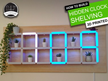
How To Build A Giant Hidden Shelf Edge Clock

Made by DIY-Machines / 3D Printing / Art / Clocks / Home Automation / Lights
About the project
A giant digital LED clock discreetly hidden in the edges of a geometric shelving system. Includes intergarted LED downlighters to show off your favorite items on the shelves. A discreet photoresistor dims the LED's when the ambient light levels drop and colours can be customised in the code.
Items used in this project

Story
Step 1: Video Guide
I have created a video detailing the build of this project. The beginning of the video shows the hidden clock in action if you would like to see it working. If you prefer written instructions broken down into steps then you are in the right place! Read on and I'll explain how to build one of your own.
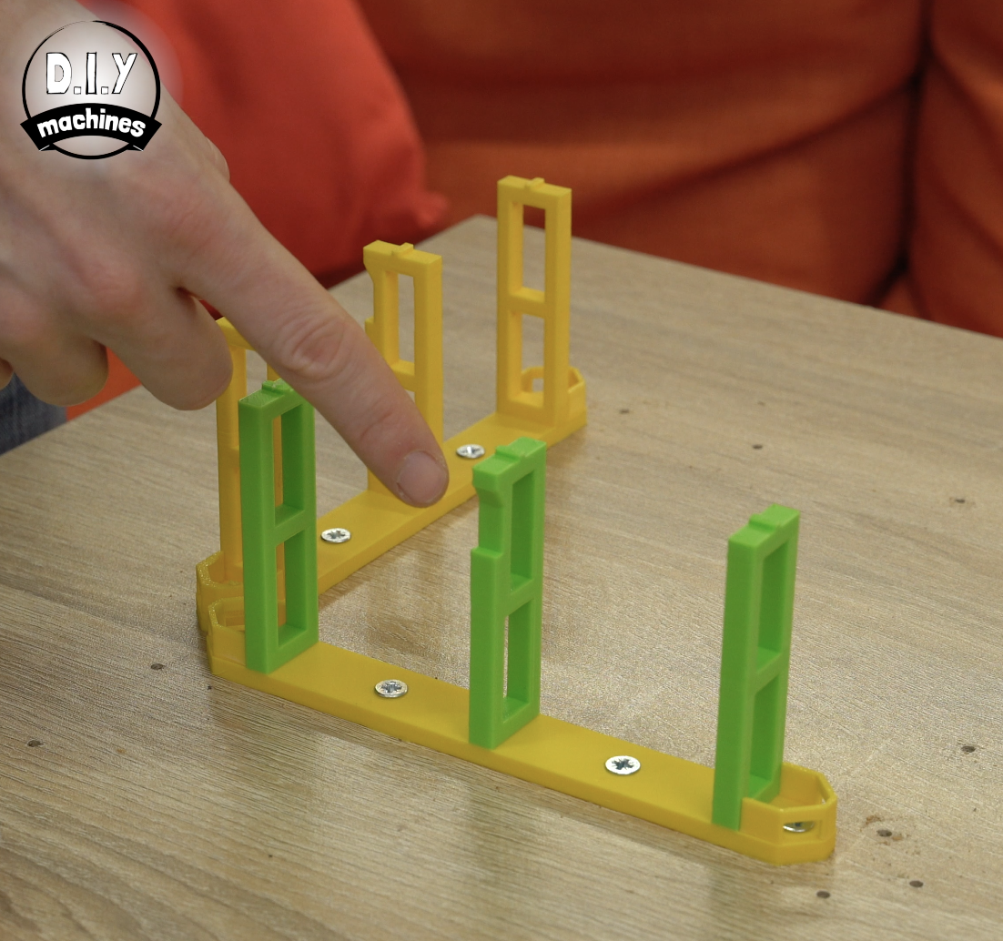
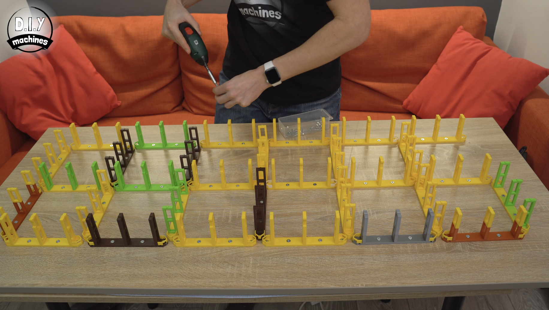
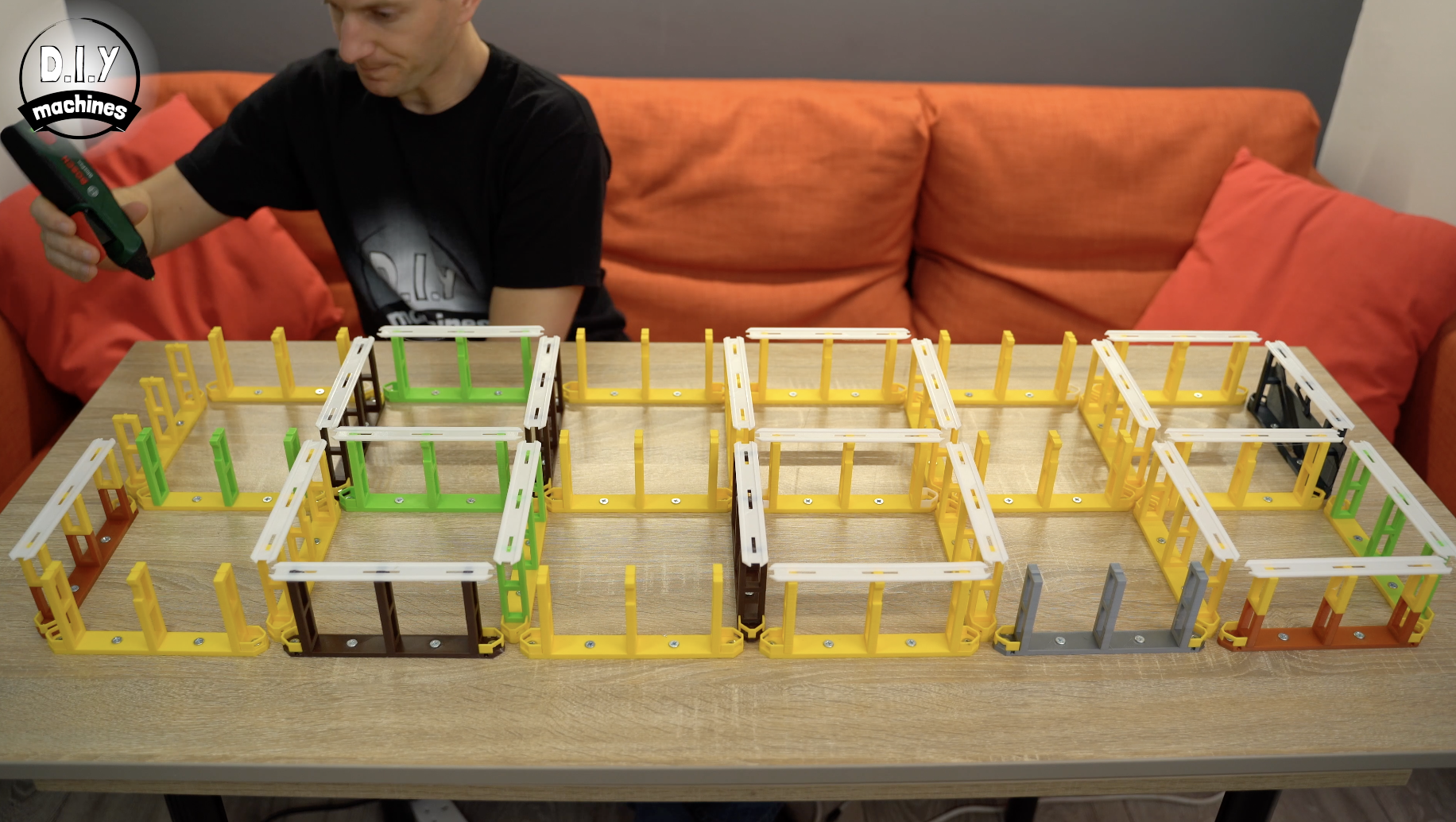
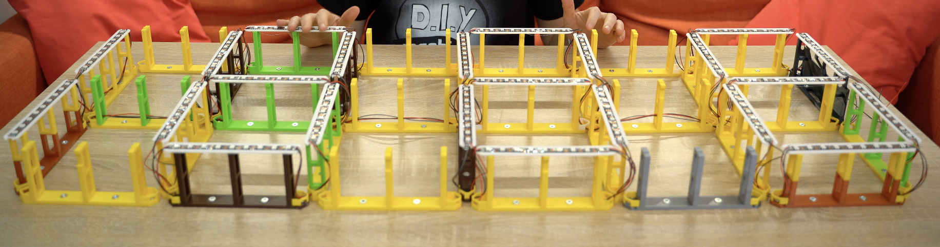
Step 2: Print the Core Supports
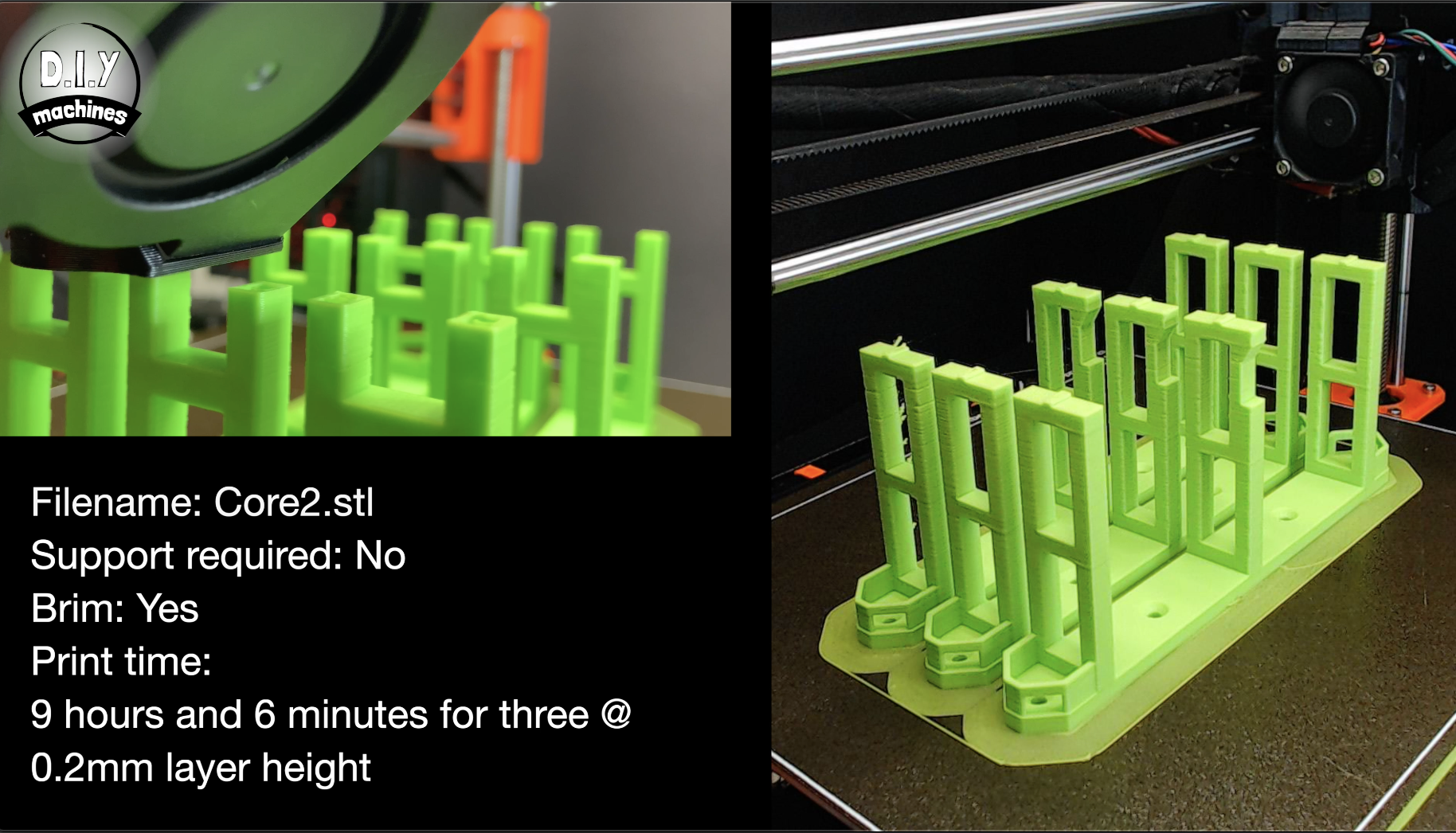
The core supports provide the framework of the shelves, handle the routing of the wires, and act as a standoff for the LEDs.
You will need to 3D print 31 of these. The files can be downloaded from Thingiverse for you to use in your slicer program: https://www.thingiverse.com/thing:4207524
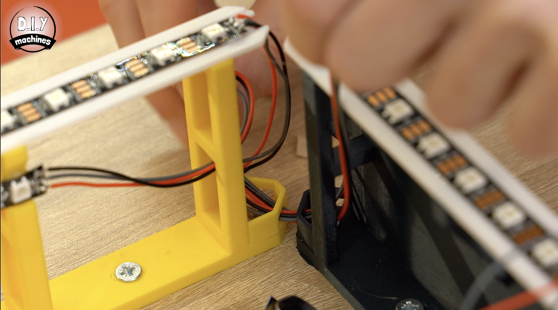
I printed mine with a layer height of 0.2mm in a mixture of ABS and PLA. As it won't be seen in the final project it is a great opportunity to use up any colours that need using up. I had several rolls of filament with only a small amount left so used these first before finishing most of them in the rather bright green and bright yellow shades shown in the images above.
Step 3: Mounting the Core Supports
There are two different ways that you can correctly space out the core supports across your backboard
I will explain first how to do it with a 3D printable template, and then the second option is using a CNC machine if you have access to one (or someone else who might).
If you are using the 3D printable template, read on. If you will be using a CNC machine to set out the holes skip the following step....
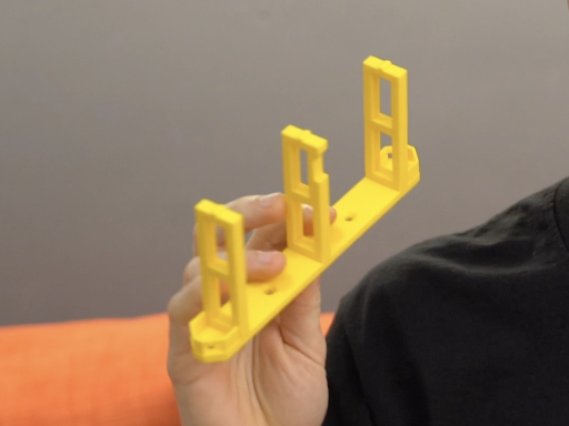
Step 4: Mounting the Core Supports: Option 1 - Using the Template

3D print the template file from Thingiverse: https://www.thingiverse.com/thing:4207524
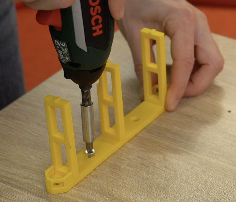
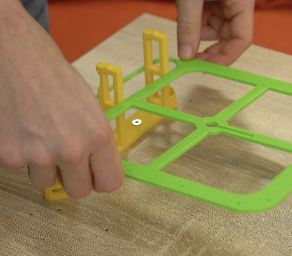
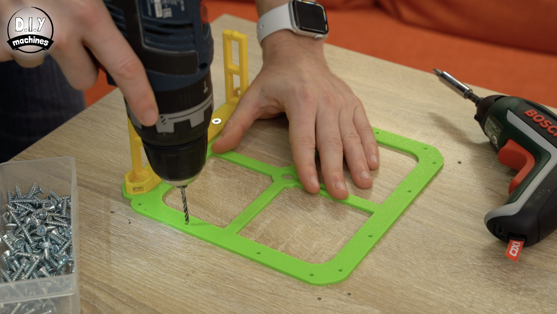
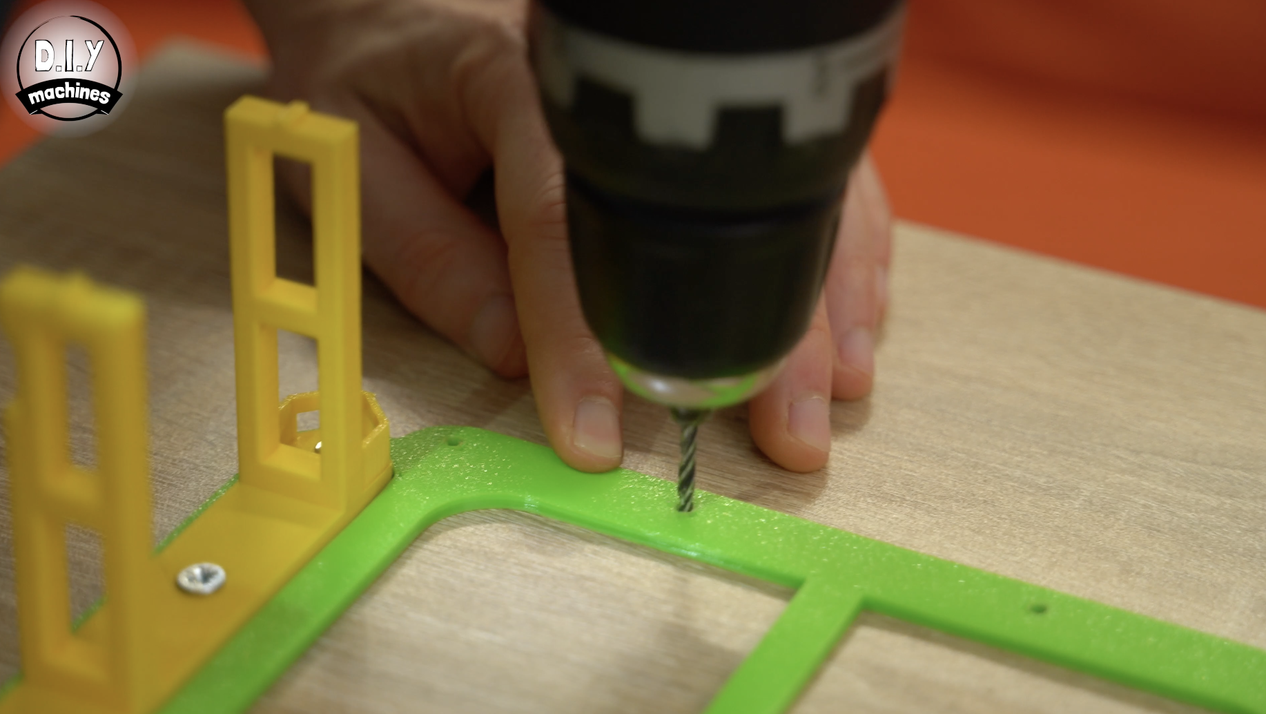
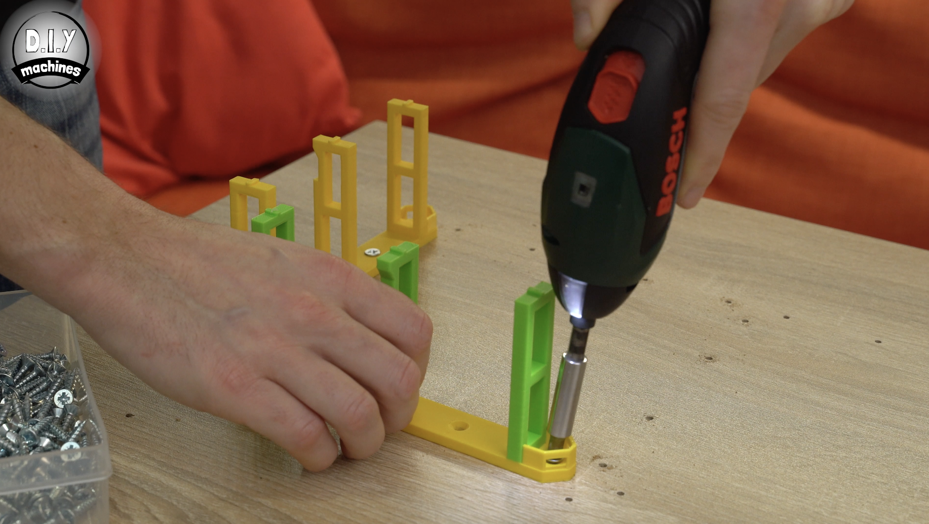
You can then screw the first core support to your backboard using some M8 (or similar) wood screws. Ensure that it is level and parallel to the board's edge. Once the first support is secured you can then lower the 3D printed template over it. This will then show you where to drill the pilot holes for the next three supports.
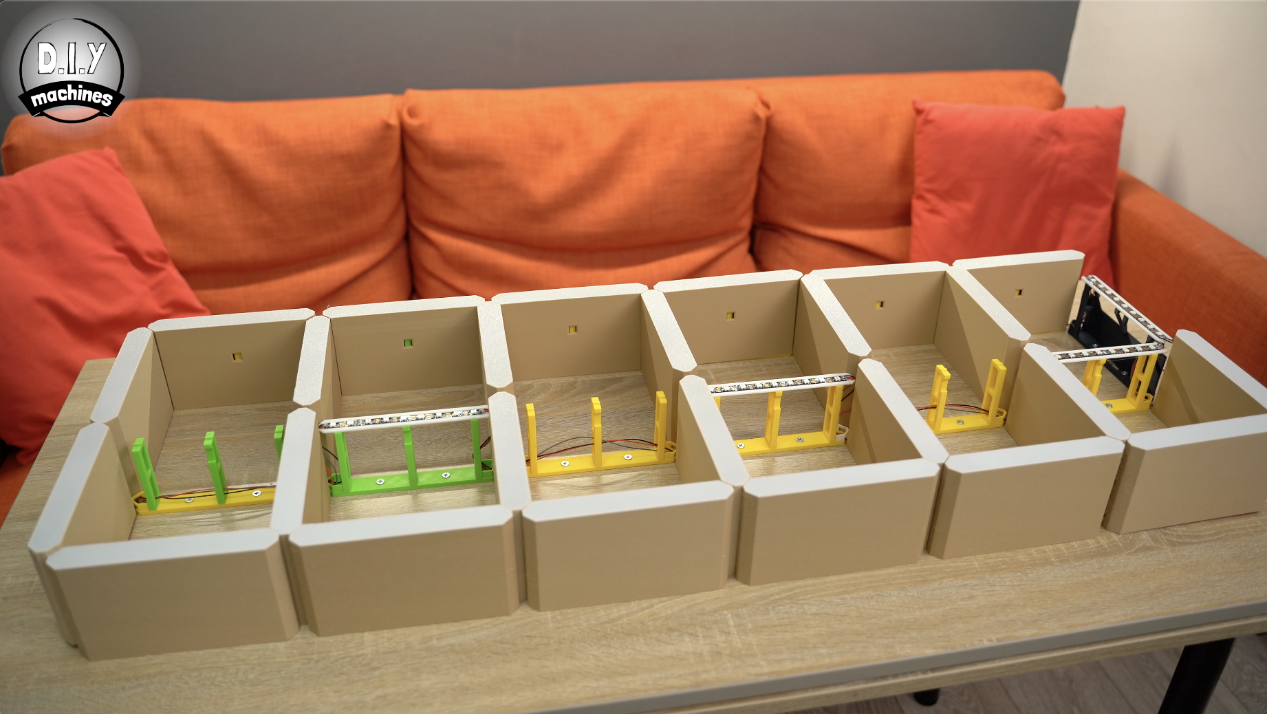
After drilling the pilot holes remove the template and fit some more supports. Ensure that the notch on the horizontal supports is facing towards the bottom of the clock when you screw them into place. This is where we will be gluing our downlighting LEDs later in the project.
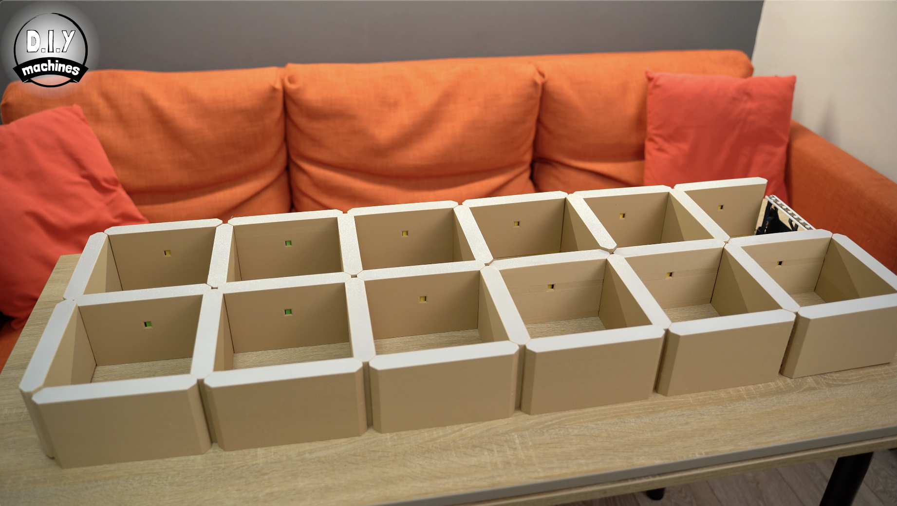
Keep fitting supports until it is six long and two high, the top right one will be left out for now.
If you used the 3D template as mentioned in this step and will not be using a CNC machine you can skip the next step.
Step 5: Mounting the Core Supports: Option 2 - Using CNC Machine
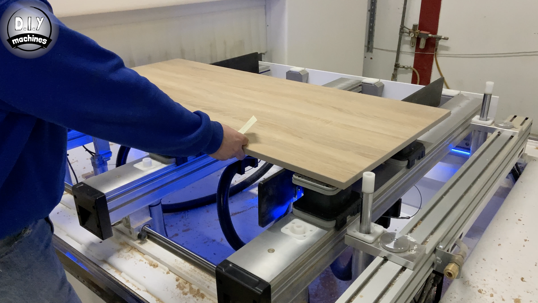
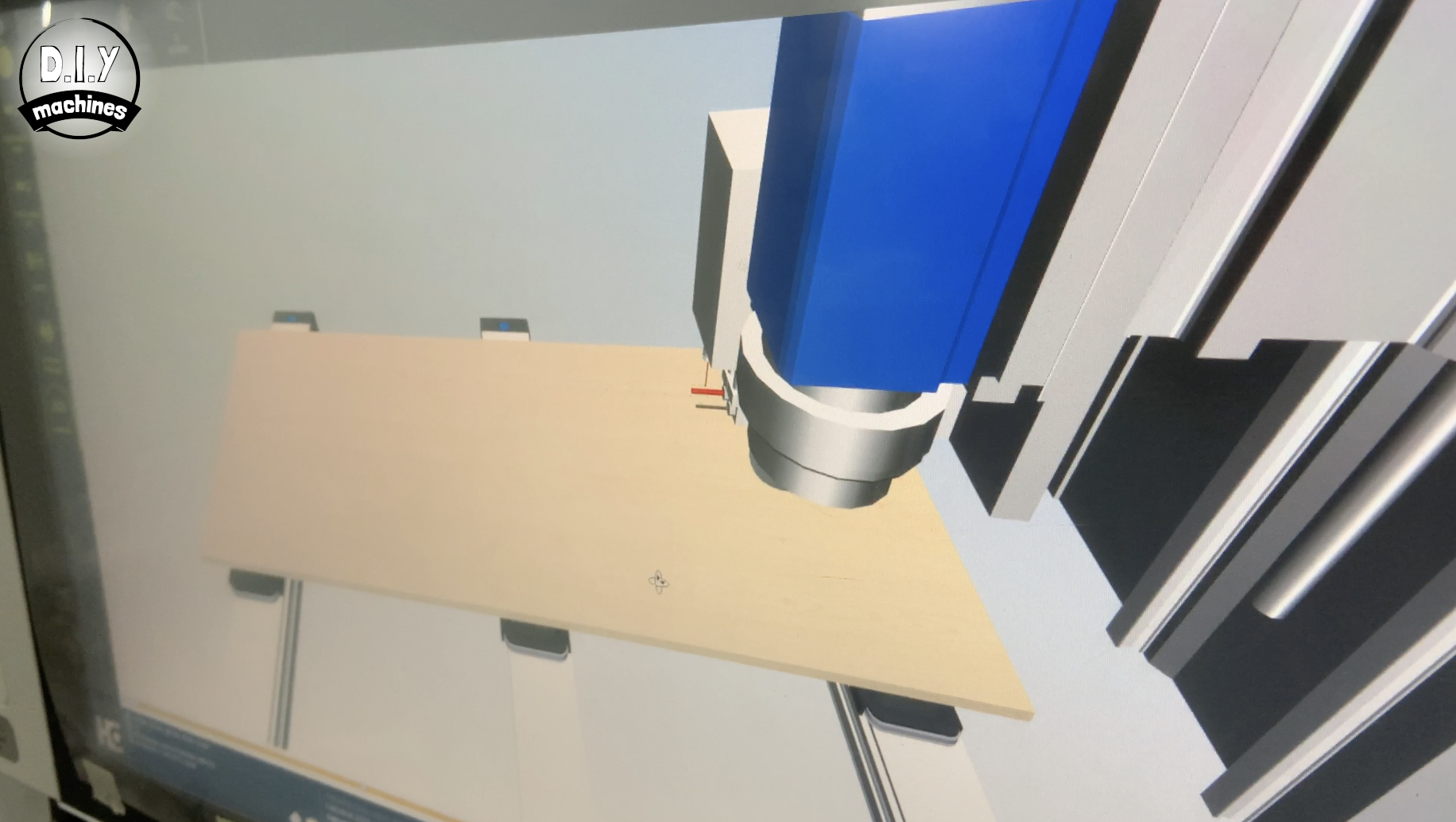
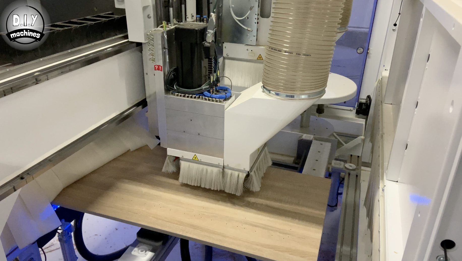

If you have access to a CNC machine you can have someone pre-drill pilot holes to allow you to quickly and easily position and fit the 3D printed supports. This is the route that I took as I used to work for a local furniture manufacturer.
You can find a technical drawing showing the positioning of the holes available to download here: https://lewisaburrow.selz.com
Once the pilot holes have been drilled you can proceed with installing the core supports.
Ensure that the notch on the horizontal supports is facing towards the bottom of the clock when you screw them into place. This is where we will be gluing our downlighting LEDs later in the project.
Keep fitting supports until it is six long and two high, the top right one will be left out for now.
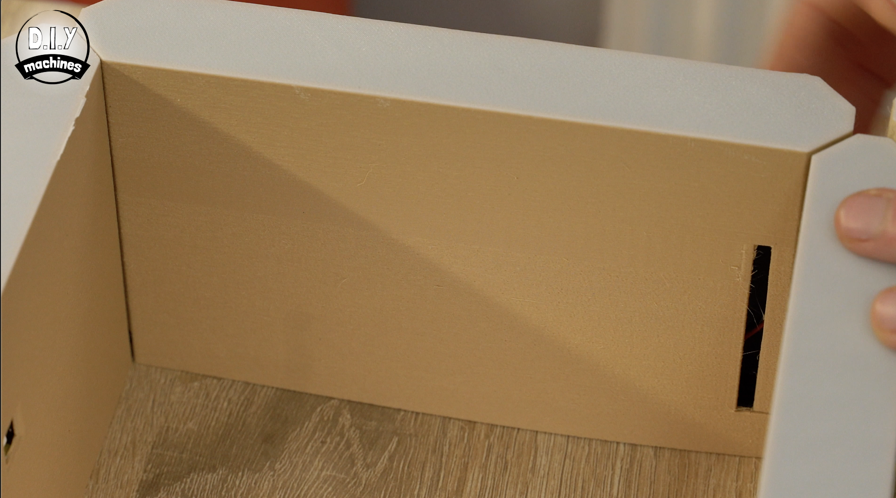
Step 6: Installing the 'electronics Hub' Core Support
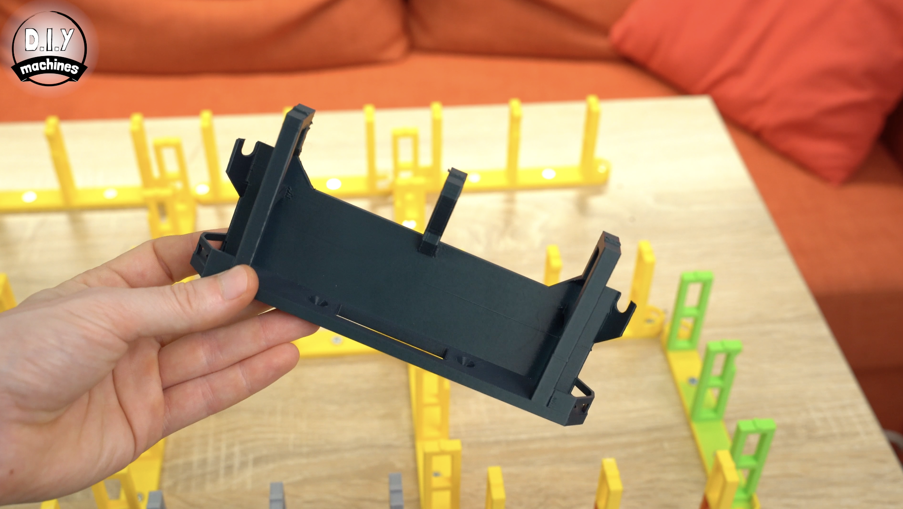
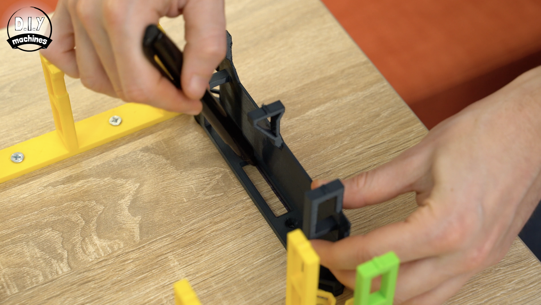
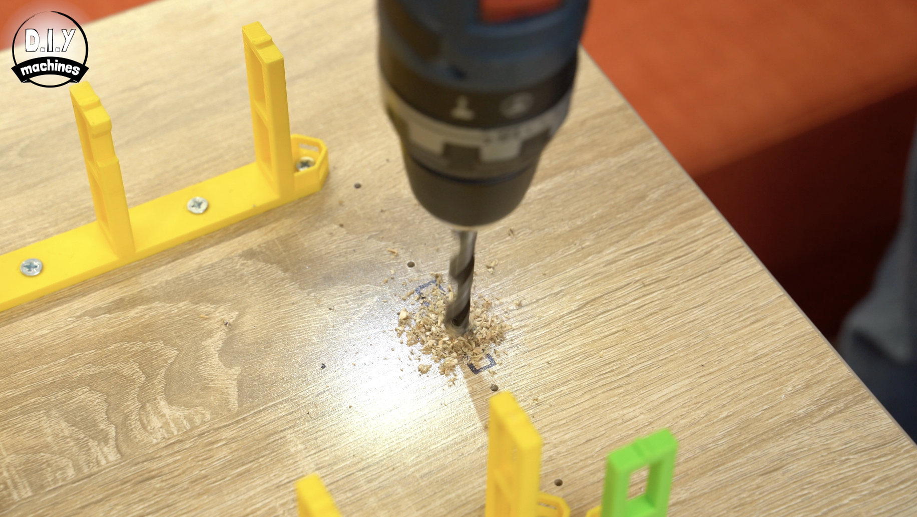
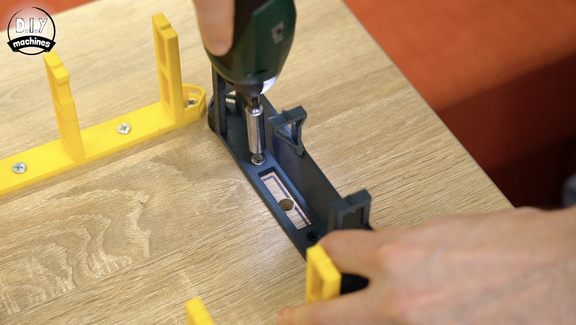
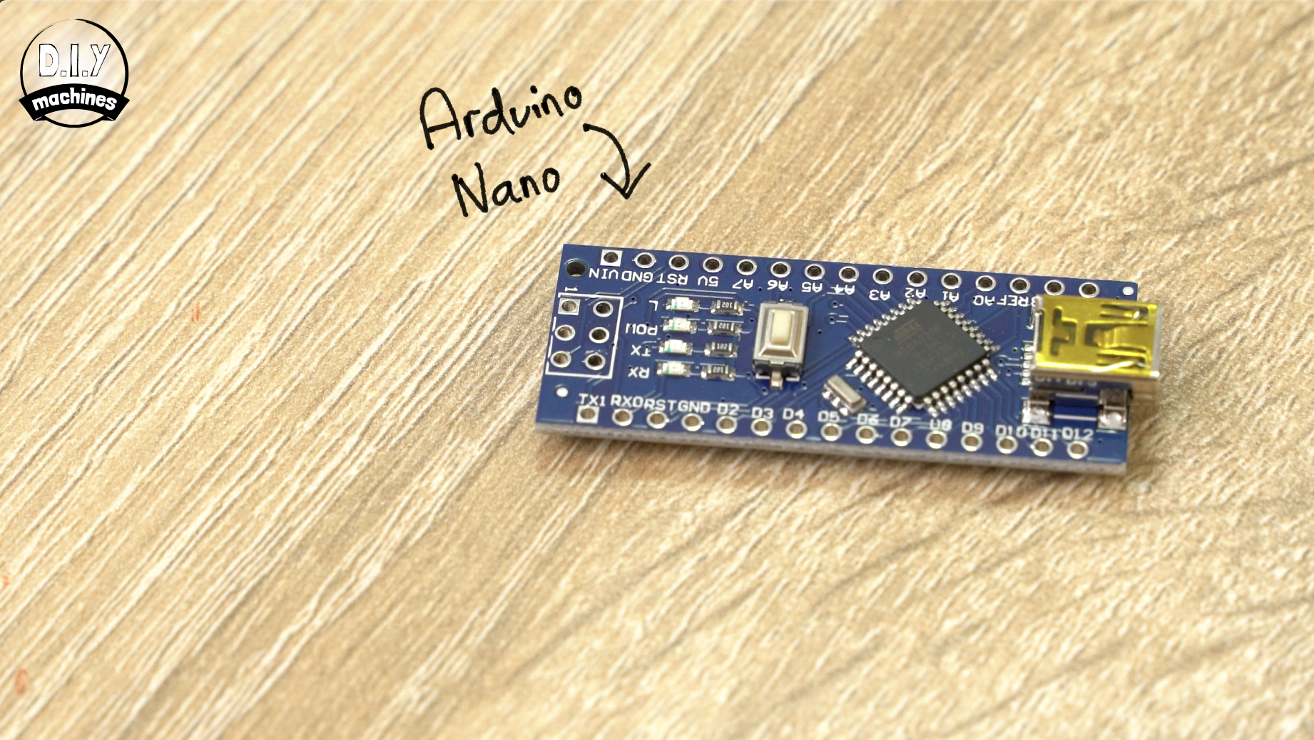
The last core support which is to go in the top right corner is a modified version of the others. It has been designed to accommodate the electronics (mainly Arduino Nano, Real-Time Clock - DS3231 and photoresistor).
This is 3D printed using the same settings as the other core supports.
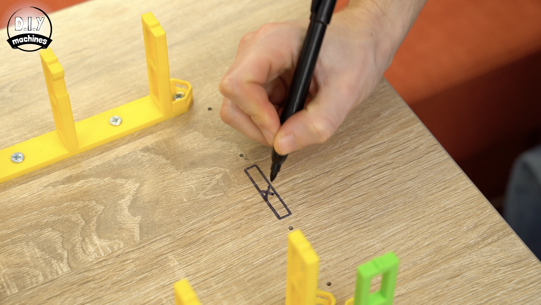
Position it temporarily other the pilot holes and use a pen or pencil to mark out the rectangular hole in its base. You can then use a drill to create a hole large enough to thread the power wire through. We'll be using this to power the clock once we have finished building it.
Once done, you can install the support using wood screws.
Step 7: Printing and Installing LED Mounts
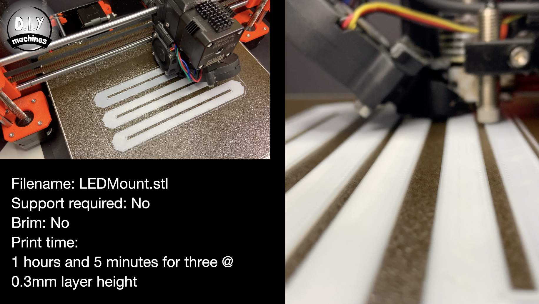
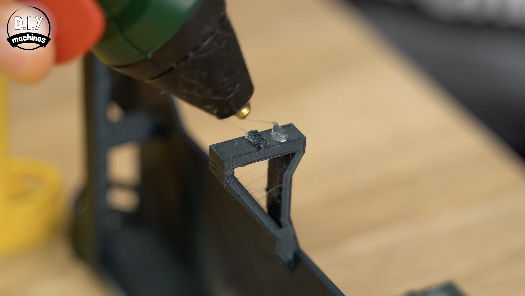
We use small 3D printed tabs to attach the LEDs to the support structure. I have printed these in white and suggest you do the same to prevent any colour cast showing through the front edges of the shelves and to increase their reflectivity.
I printed mine in PLA at a layer height of 0.3mm.
You need to print 23 of these. (I printed mine three at a time).
Once printed use some gue to attach them to the top of the supports as shown in the attached diagram.
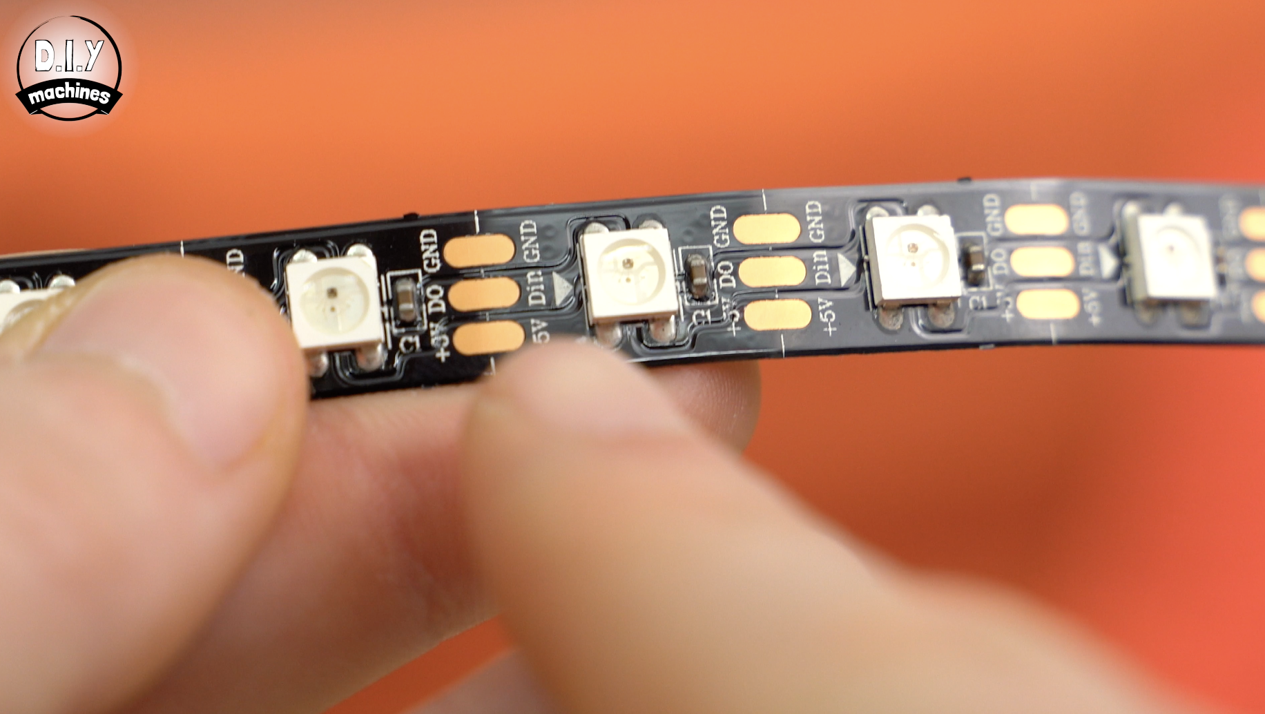
Step 8: Prepare the Clock Face LEDs
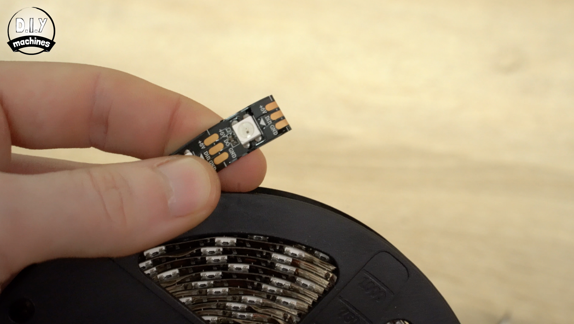
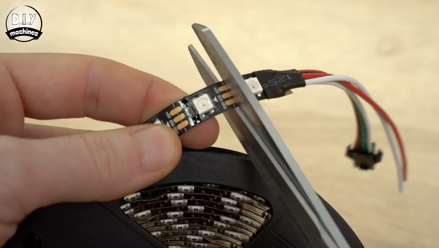
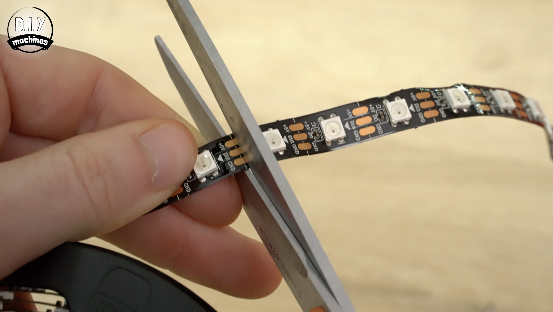
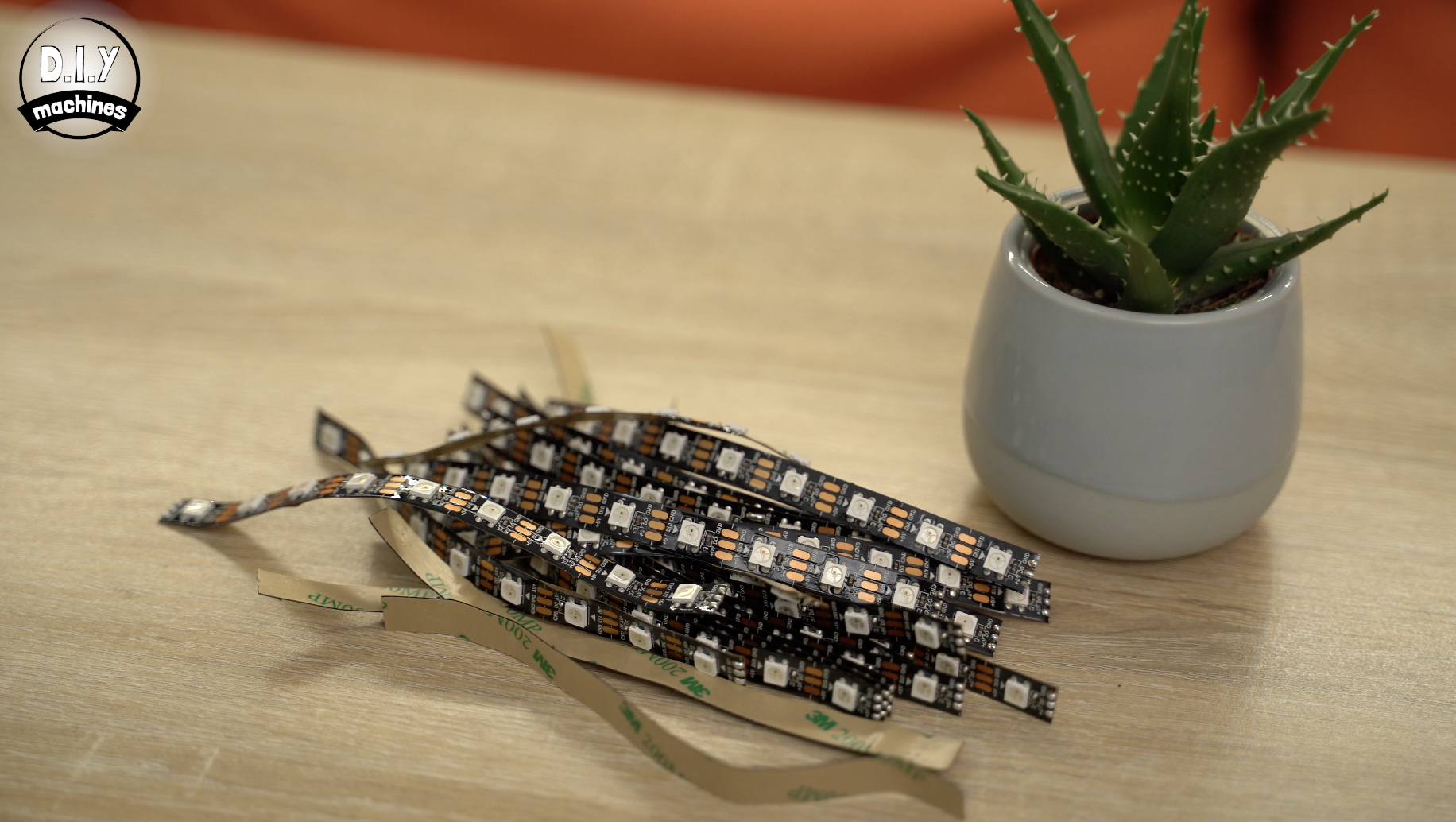
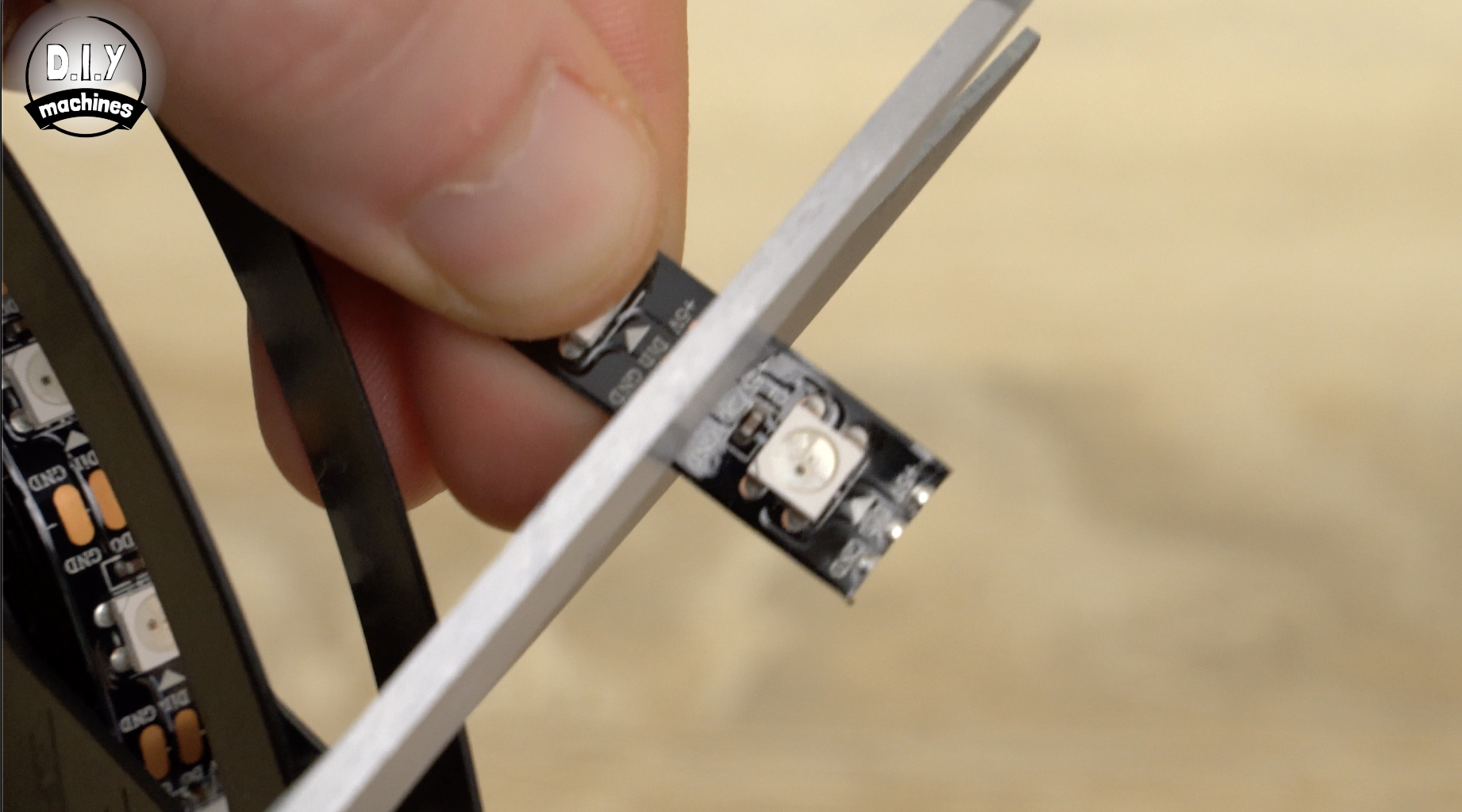
We need to prepare 23 lengths of 9 LEDs from our roll of LEDs.
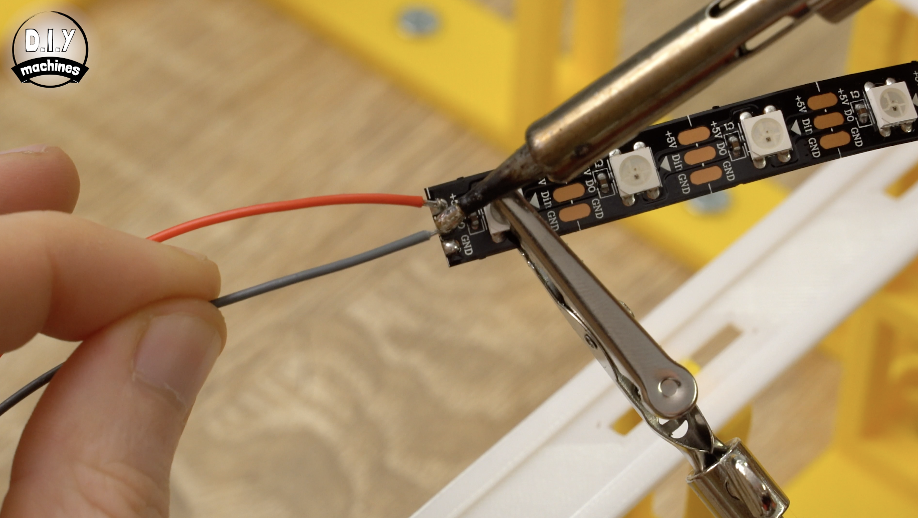
To do this use scissors to cut through the centre of the first set of copper pads thus removing the plug. Repeat this again after 9 LEDs to give us our first strip. You then need to repeat this 22 more times.
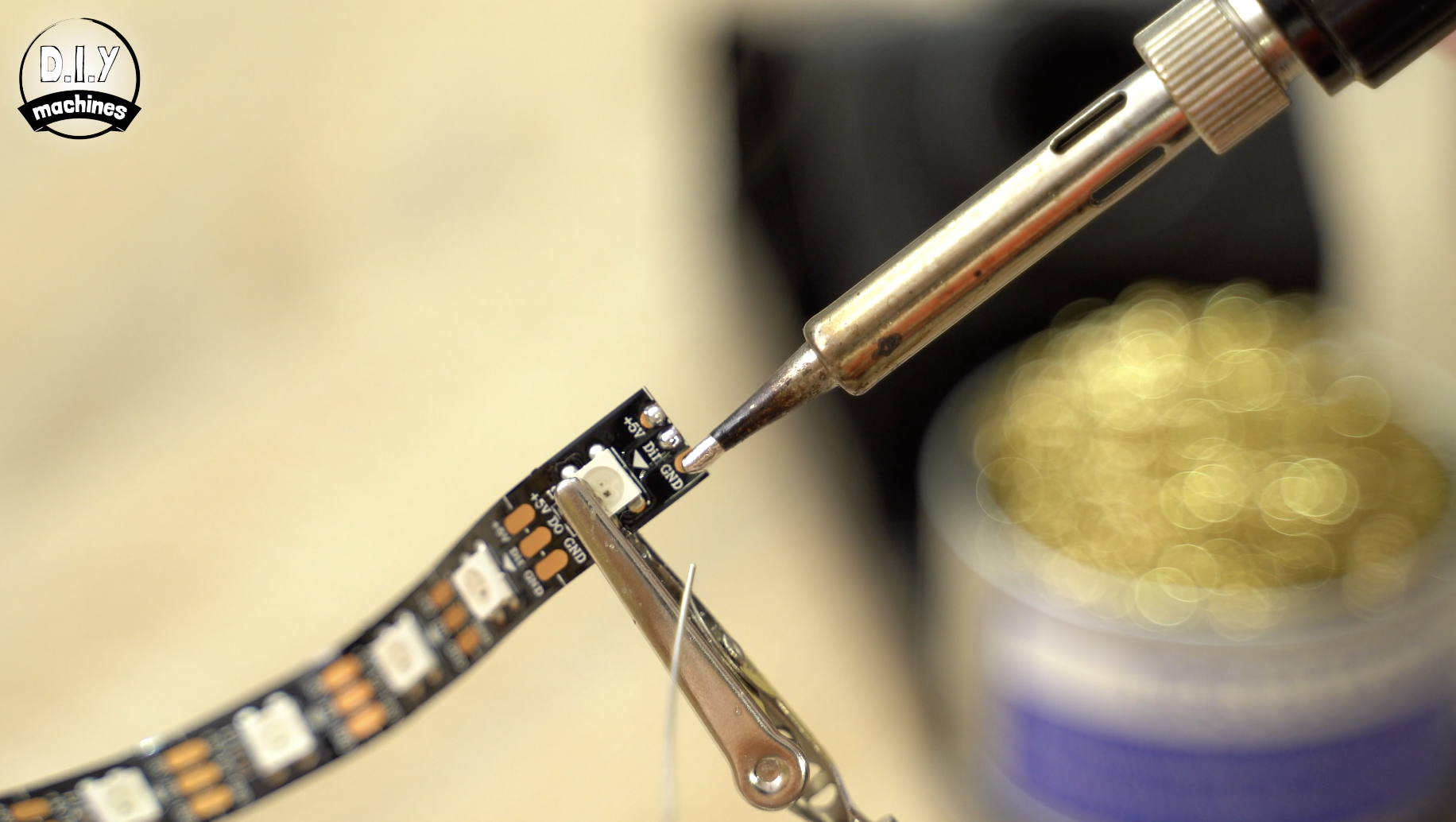
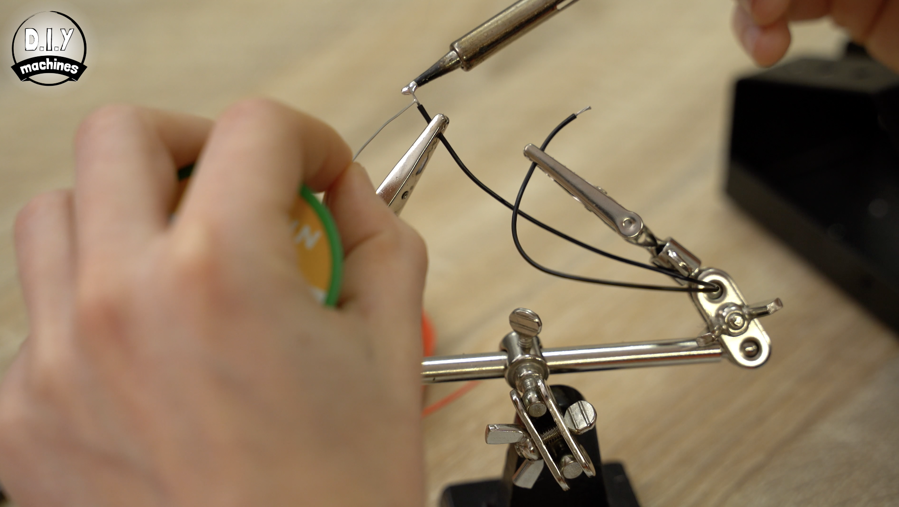
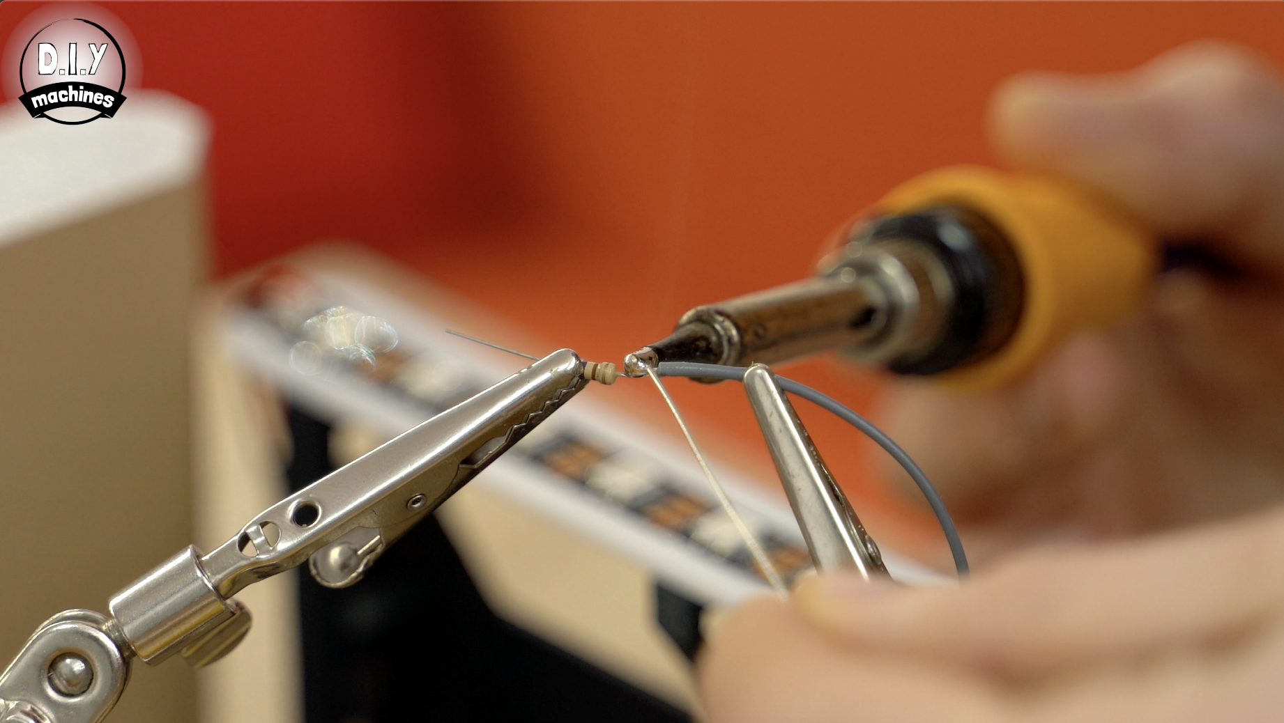
Once this is done we can 'tin' the pads of the LEDs. Though this is optional it makes it much easier to connect the wires later. Tinning the pads means using a soldering iron to add and leave a small amount of solder on each pad.
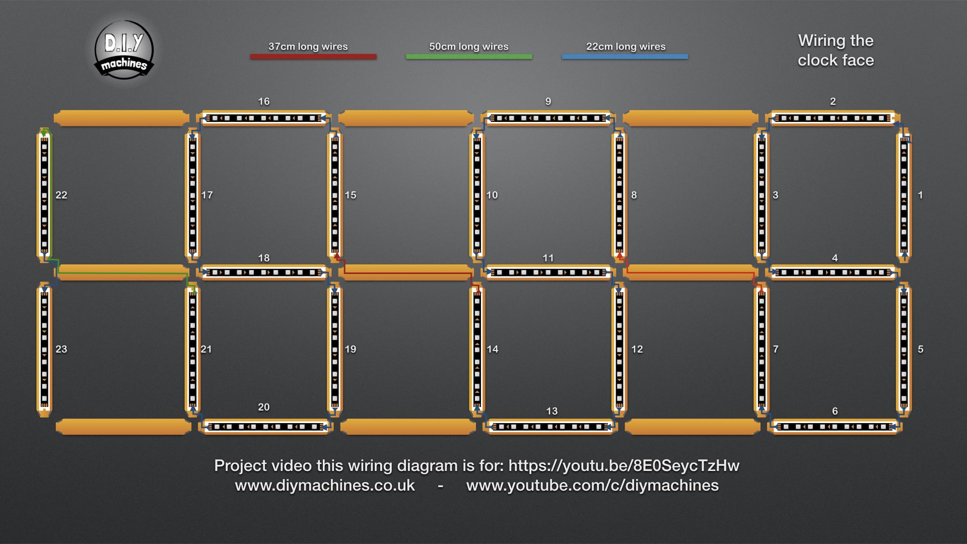
Step 9: Prepare Clock Face Wires
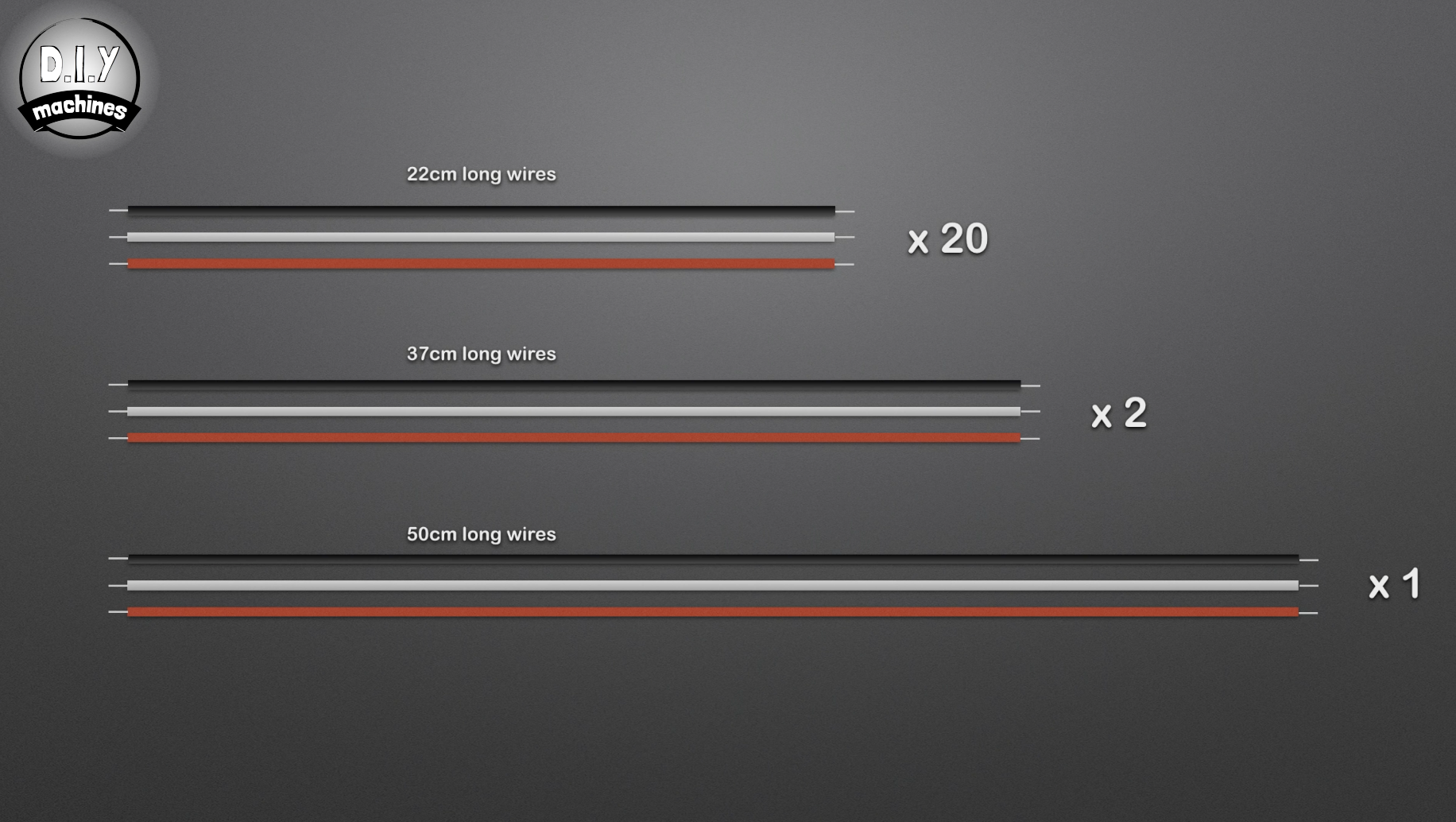
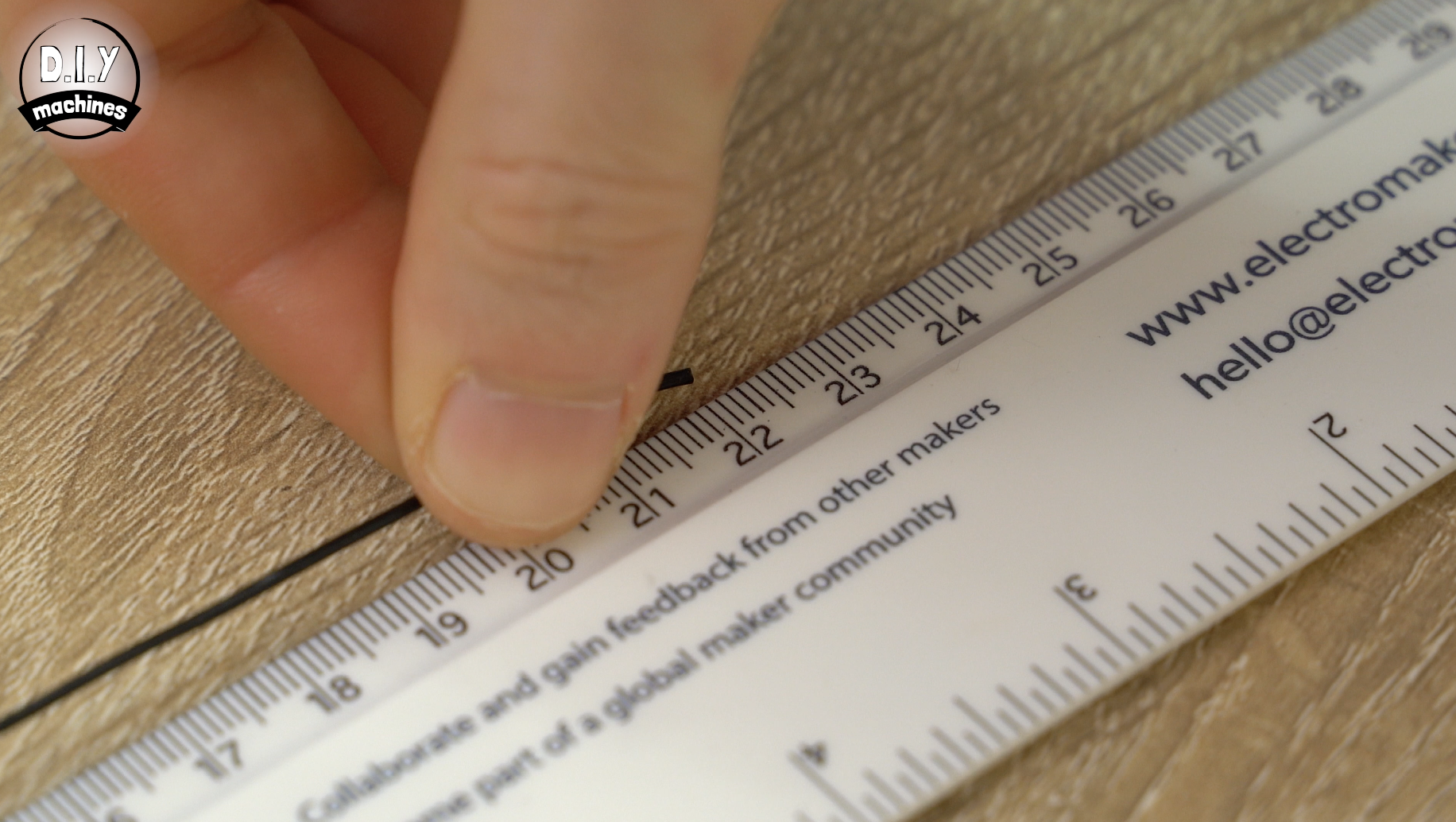
Prepare some lengths of wire in sets of three. One each for the power, data and ground connections on our LED strips.
You will need:
- 20 sets which are 22cm long
- 2 sets which are 37cm long
- 1 set which is 50cm long
As before, tinning both ends of each wire will make connecting them to the LEDs easier.
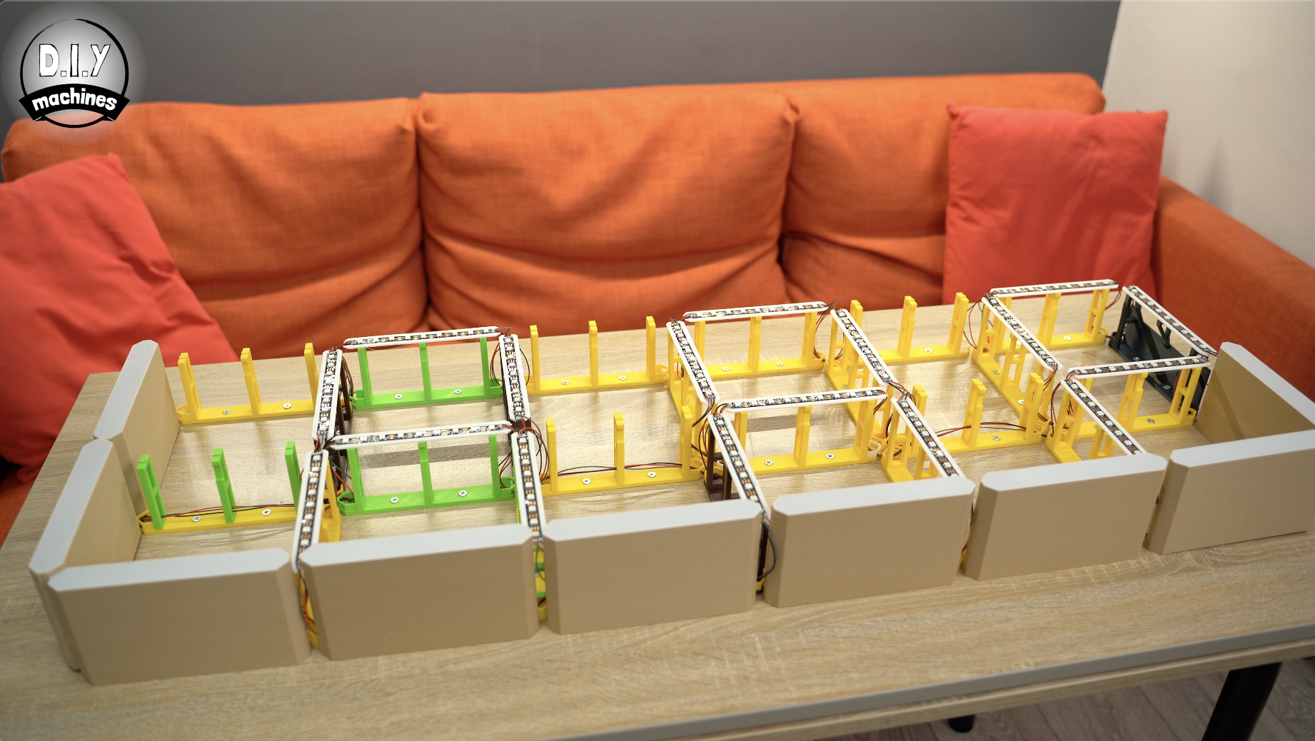
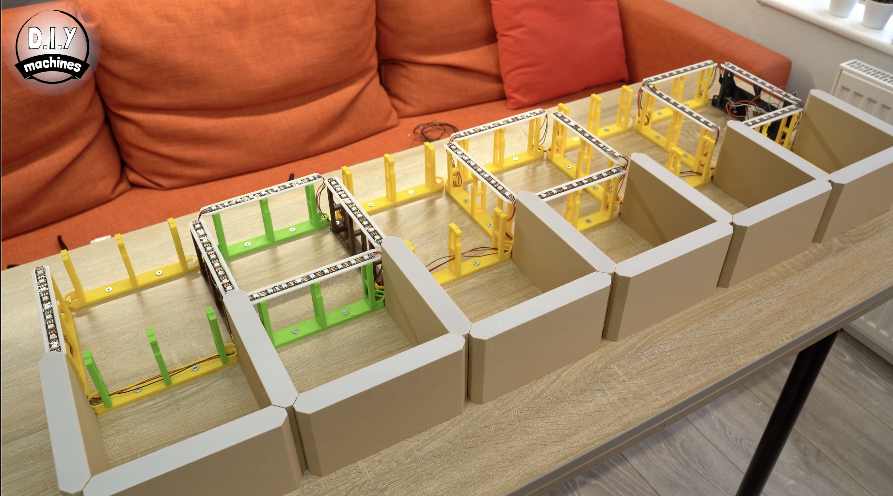
Step 10: Installing the First LED Strip
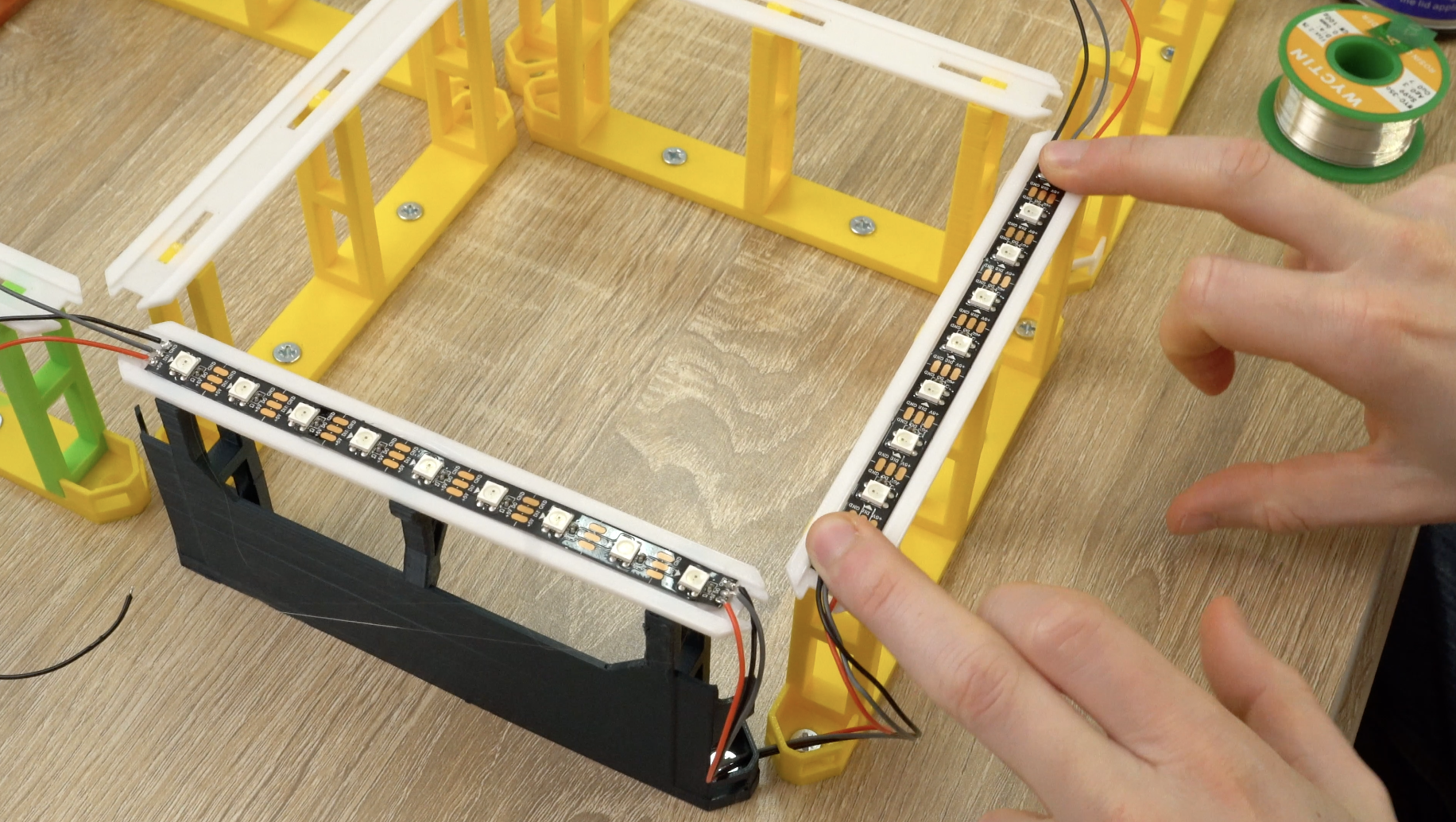
Now that the LEDs and their wires are prepared we can start to assemble them onto the front of our clock face. The order in which the strips are connected, and their orientation, is very important. There are little arrows going along the length of the LED strips which represent the direction of data flow. Pay good attention to these as you assemble your clock.
Our first LED strip will sit on the white LED mount above the unique support we printed to house the electronics in the top right corner. Attach two separate sets of 23cm long wires to both ends of one of the 9 long LED strips from earlier.
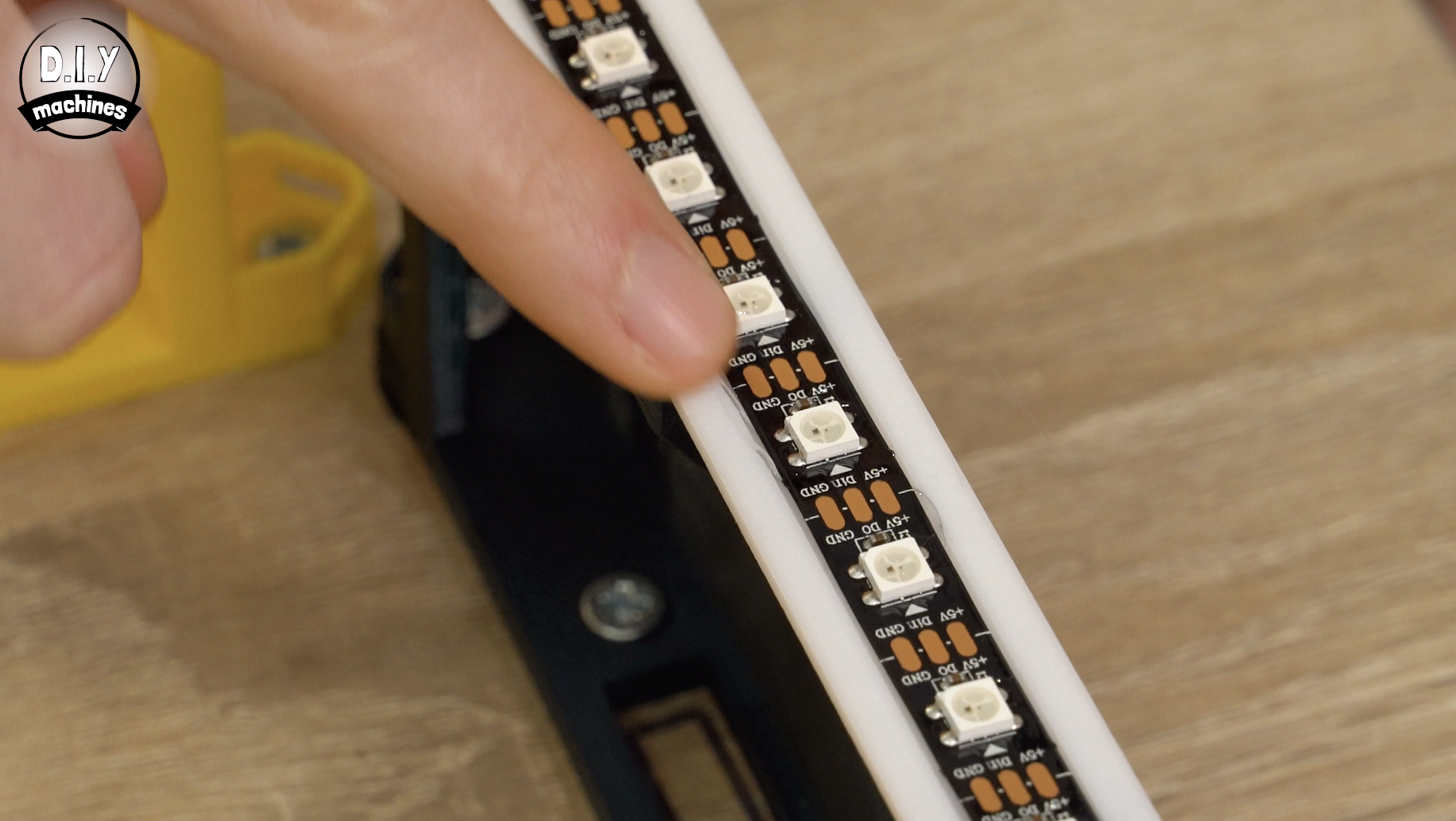
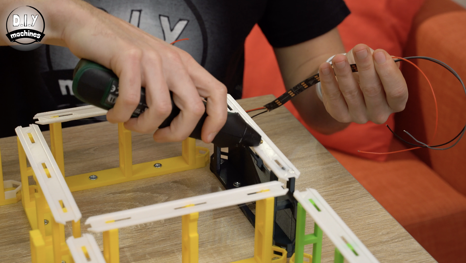
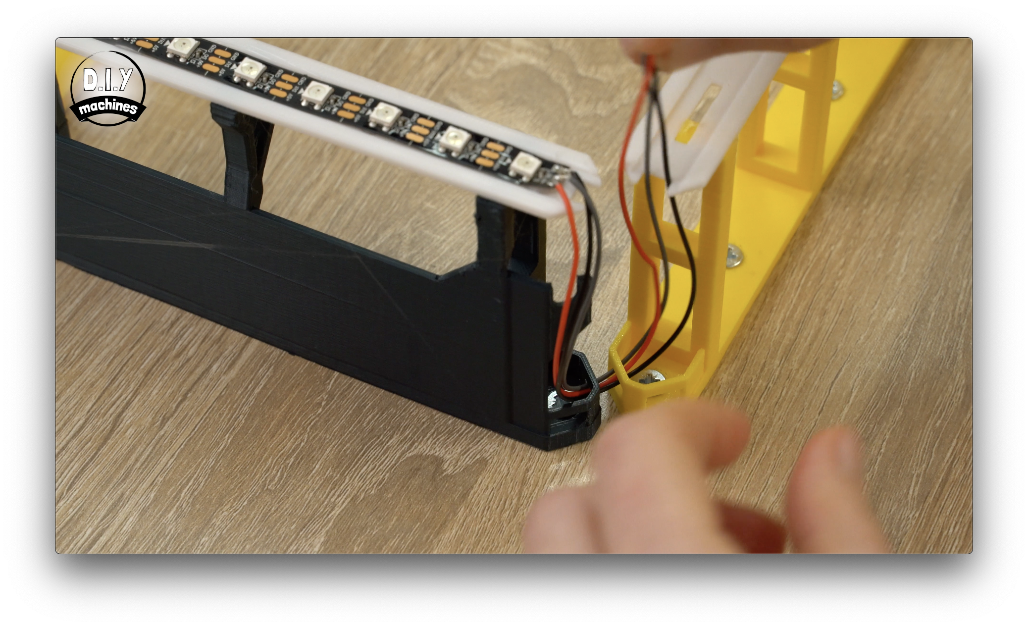
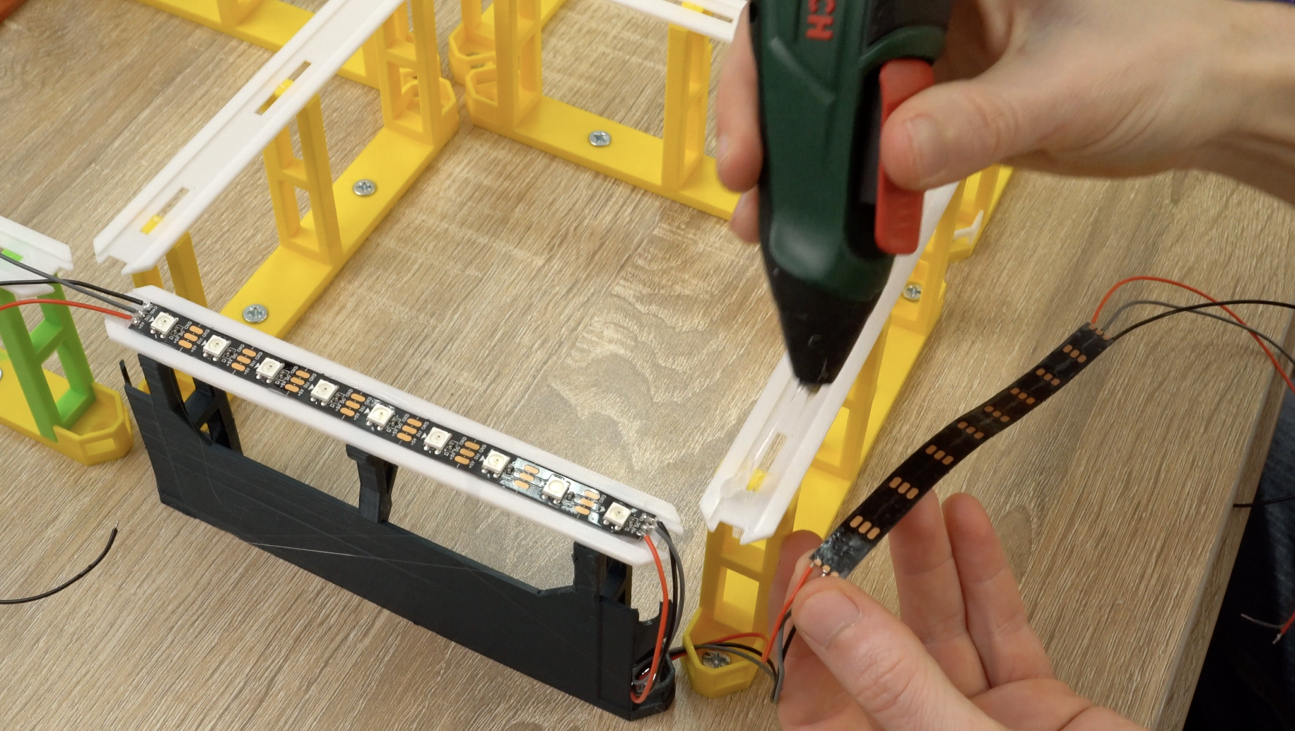
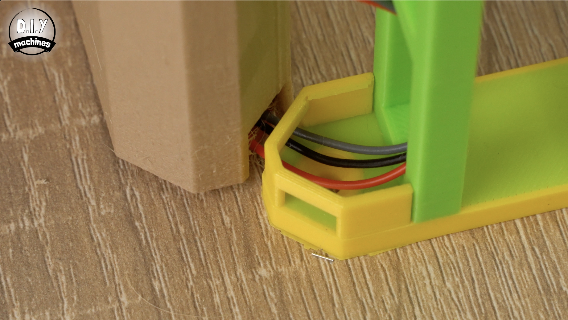
Remove the self-adhesive backing from the rear of the LEDs and also apply some glue to the top of the LED mount (for extra grip as I found sometime mine would come unstuck without the additional glue) you can then position the strip in place ensuring that the data directional arrows are pointing towards the top of the clock.
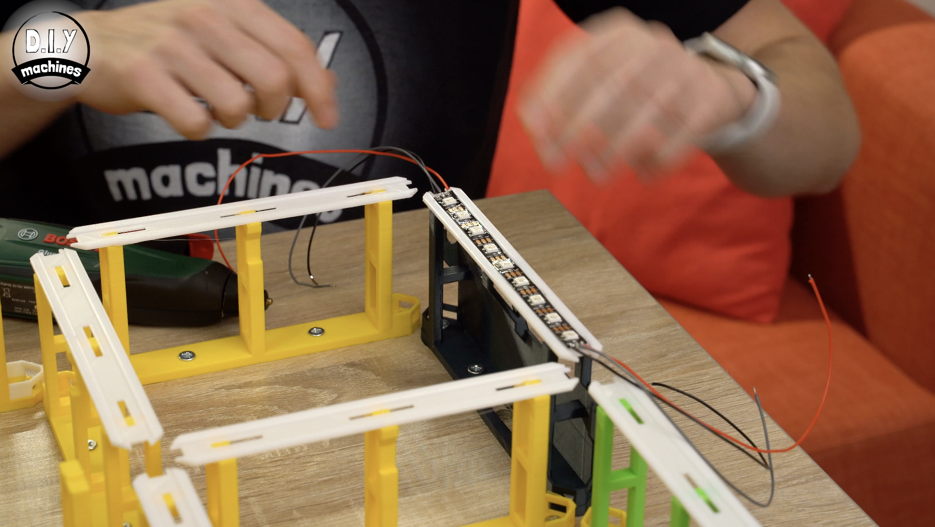
Now route the wires at the corner of the clock face down through the wire guide on the support they are on, through and into the adjacent support and up. Whenever you are routing wires along the outside perimeter of the clock ensure you use the inside holes on the wire guides. This will mean the wires are completely hidden when we finish off the clock by adding the 3D printed sleaves to the shelves (which we have not yet printed yet so don't panic!).
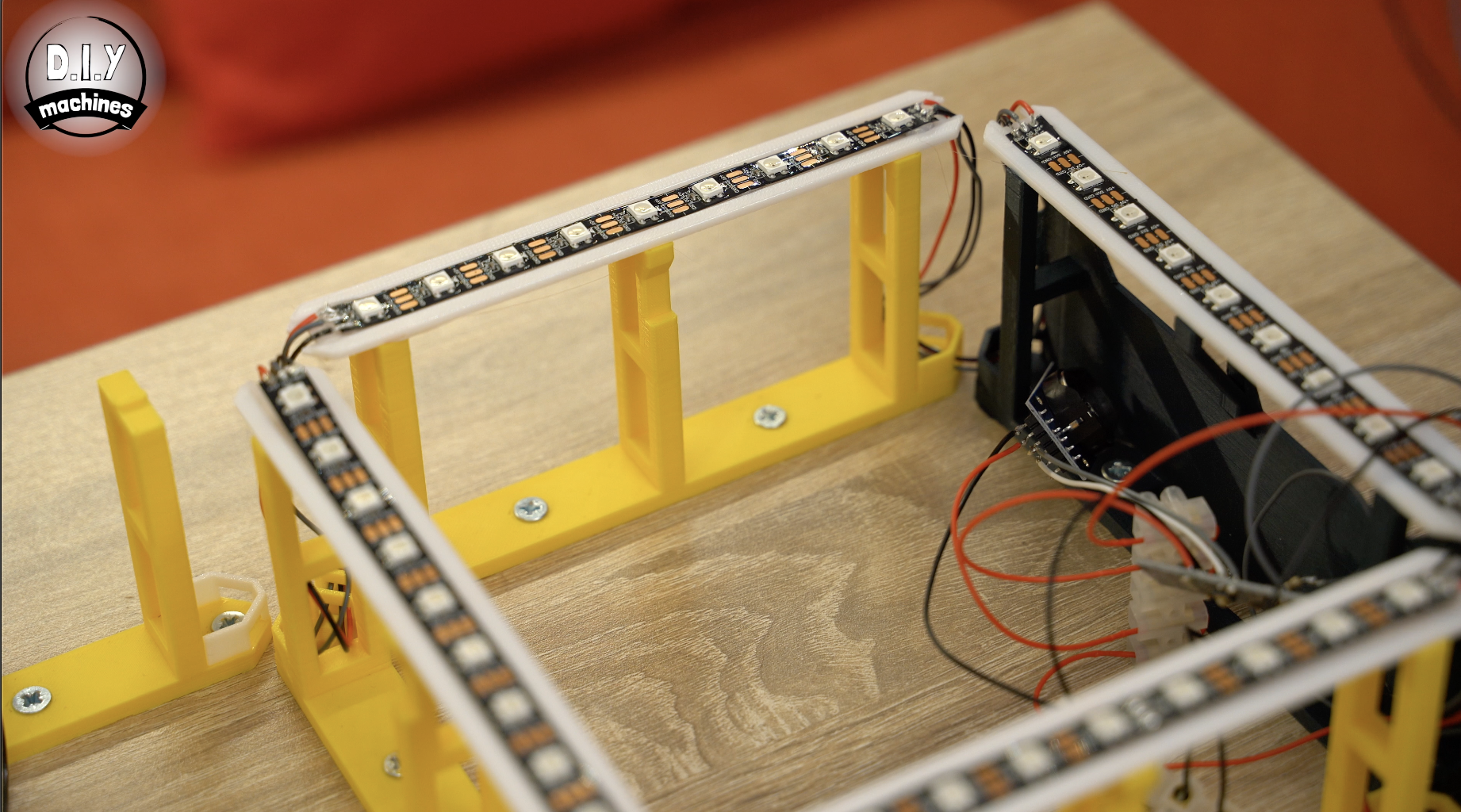
Step 11: Installing the Remaining LED Strips
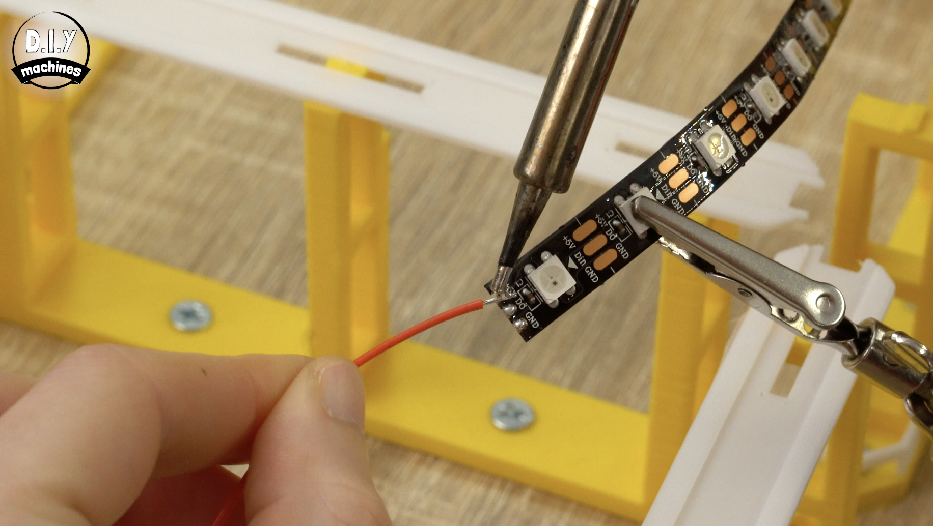
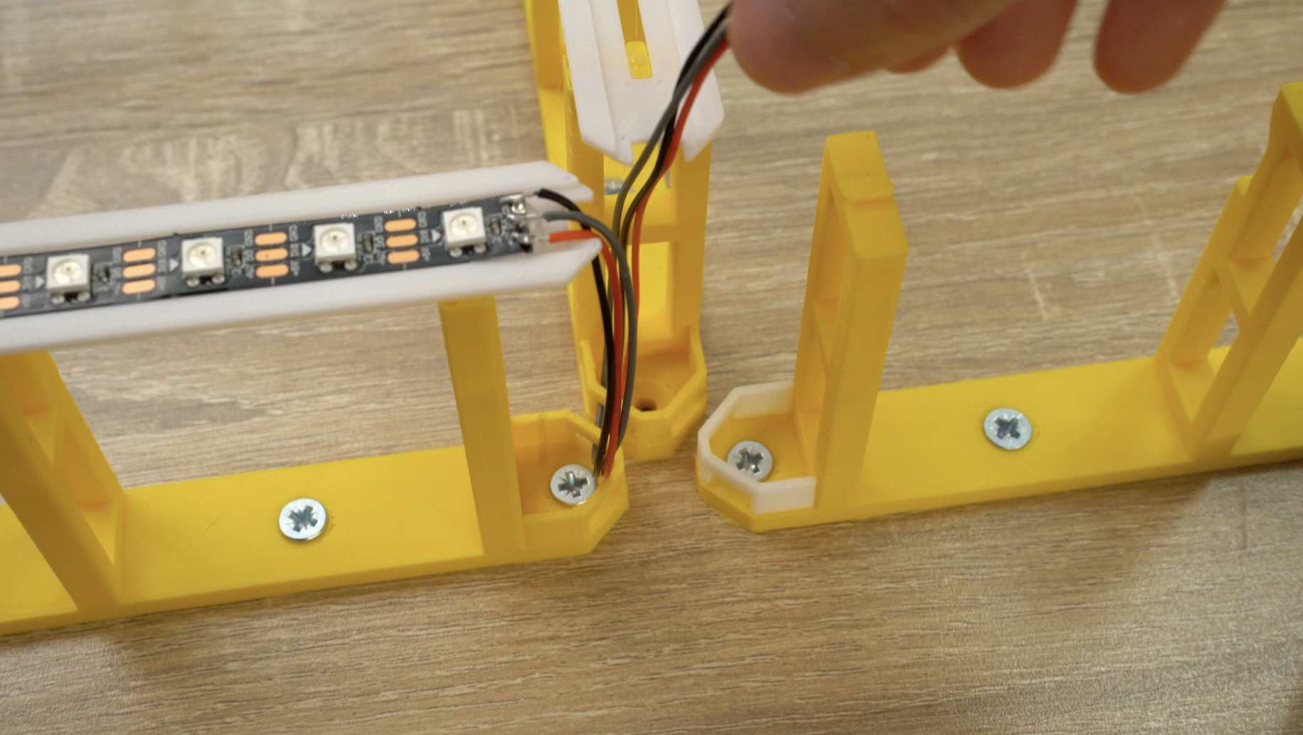
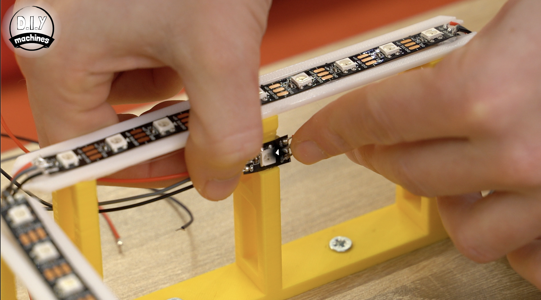
For the next strip, take another set of 23cm long wires and solder these to the outgoing side (the end the data flow arrows are pointing towards) of a fresh strip of nine LEDs.
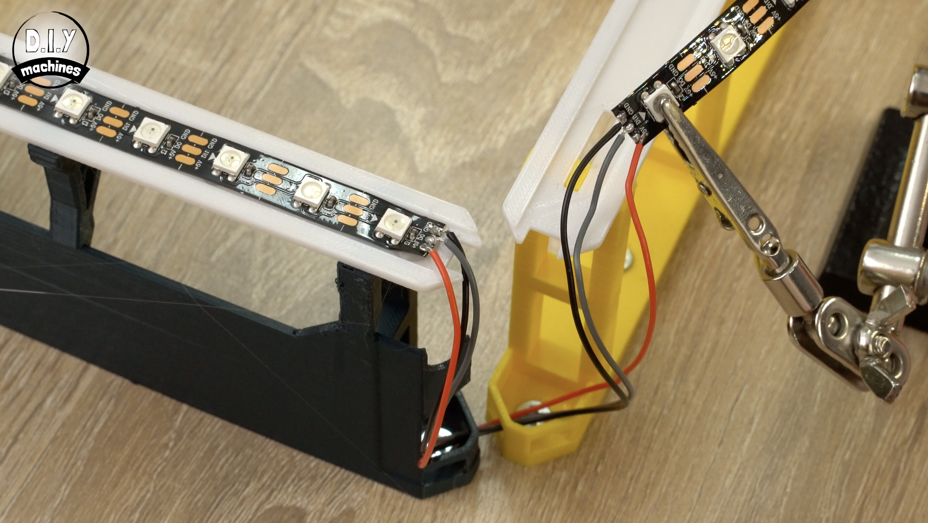
Solder the incoming side of the LED strip to the wires just routed around the corner from the previous strip. The adhesive backing can then be removed on this strip, some glue applied to the white LED mount and the strip fitted ontop.
The wires coming from this one are routed through the support and turn 90 degrees to the left up into the next support.
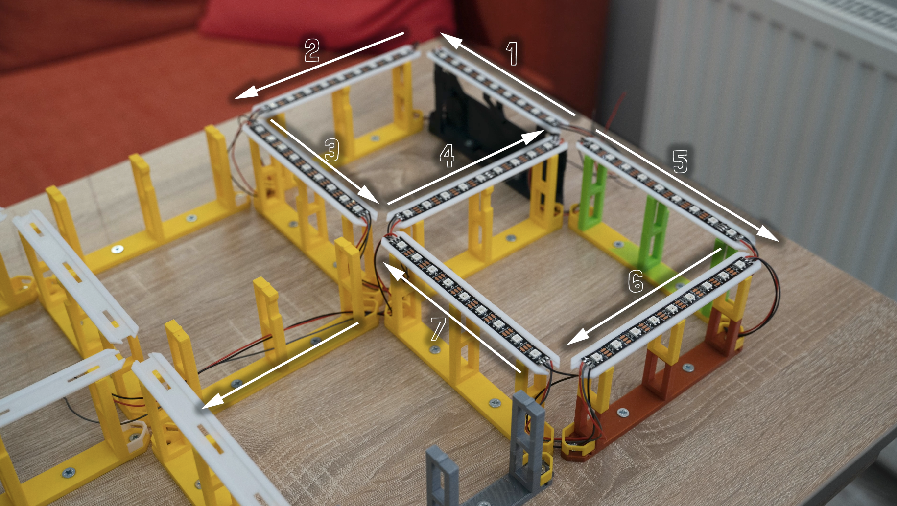
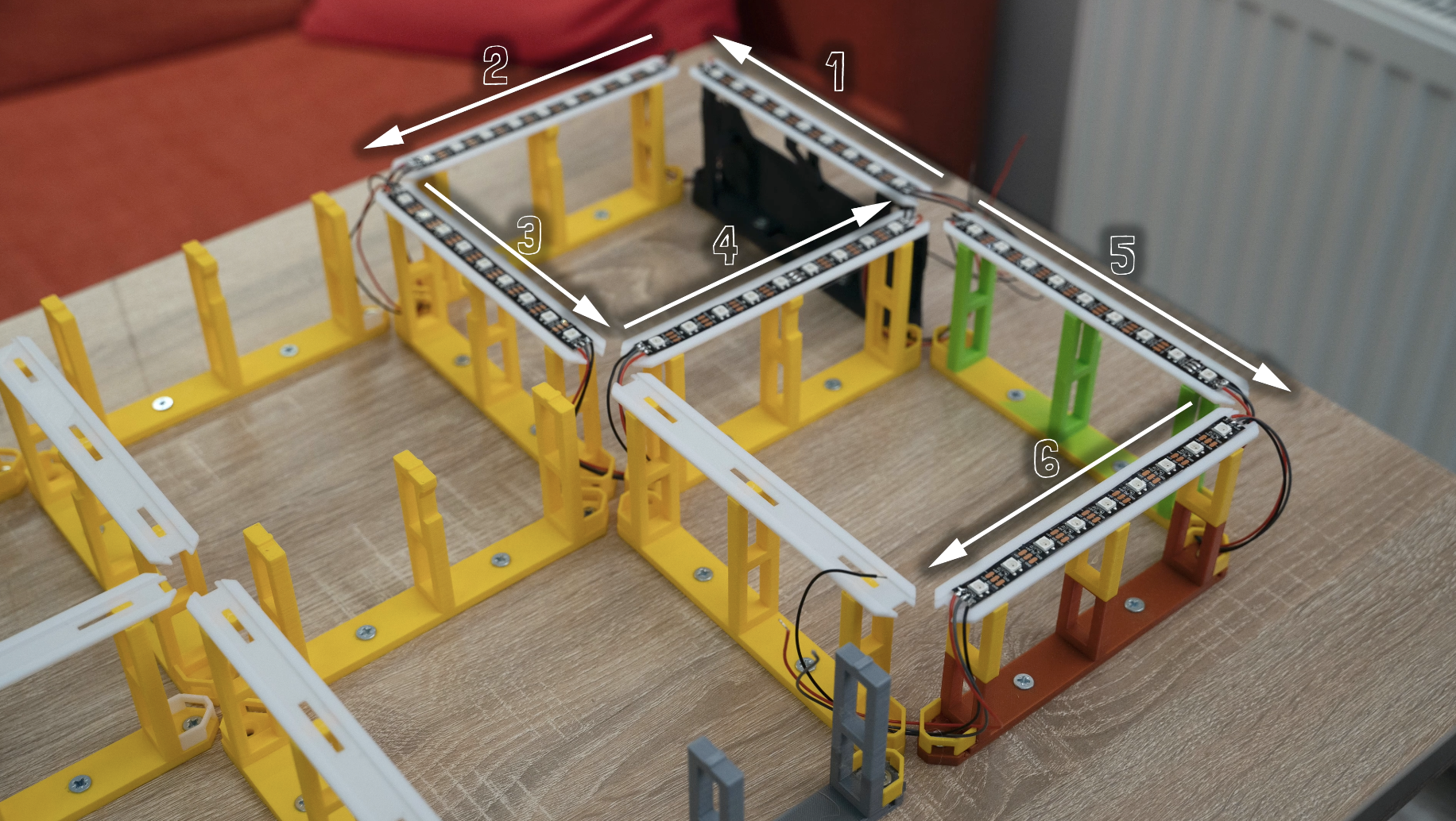
Repeat the same steps four more times following the path around the clock as shown in the diagram above. When you get to seventh LED strip you need to attach a 37cm set of wires to its outgoing side instead of the usual 23cm wires.
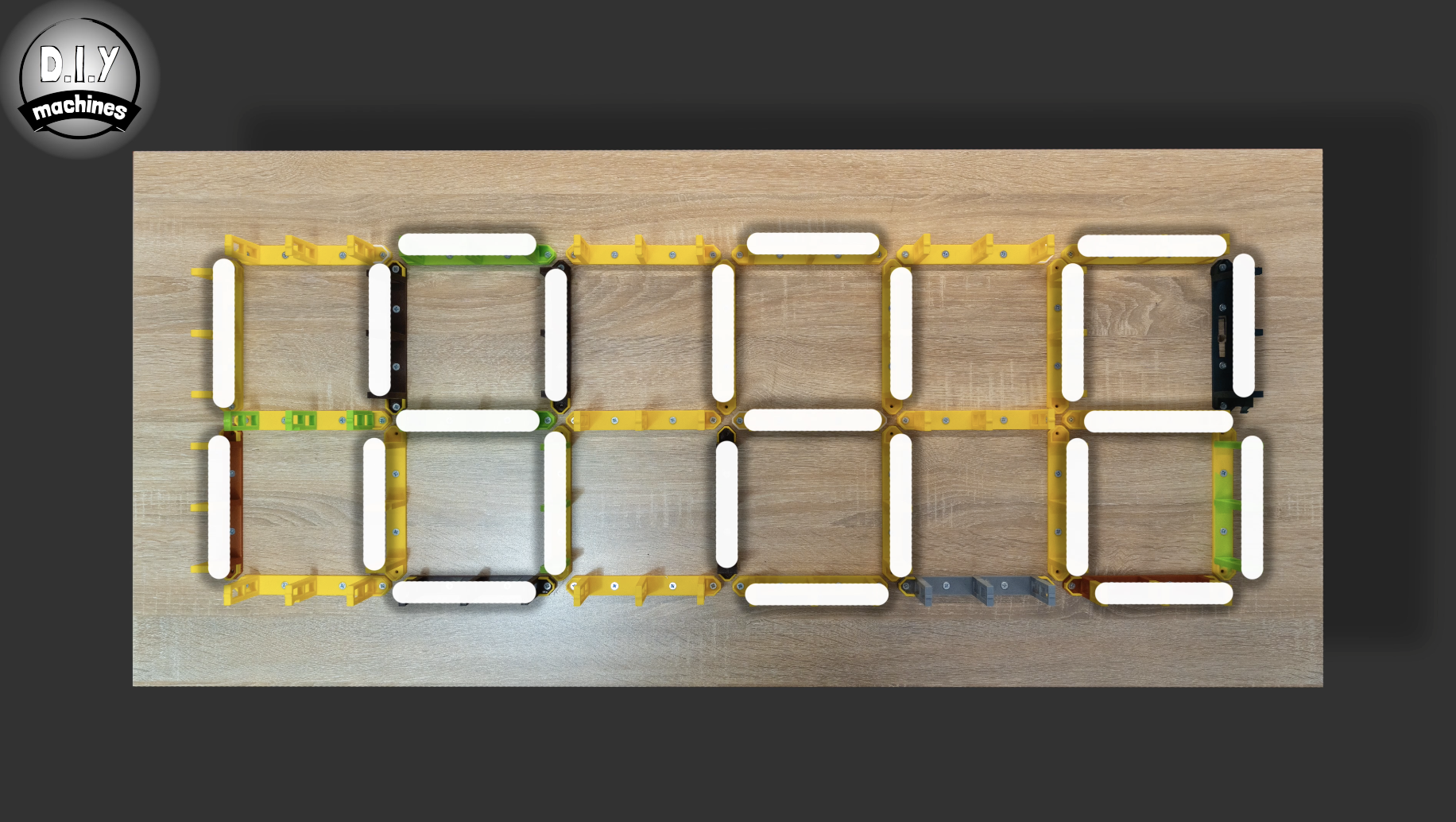
Now that I've explained and shown you the first few connections you can follow the rest using the diagram I have added above (the one on a dark background). It shows you which lengths of wire to use where, the direction of the LED strips, and how to route everything. It's a lot easier for you to follow this than for me to explain every connection in words. (Plus it would not be great fun to read either).
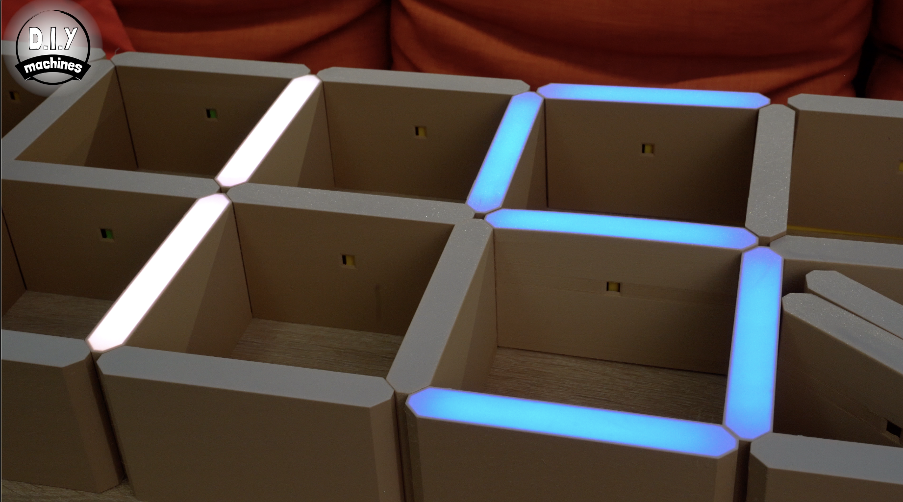
After you have finished installing the clock face LEDs it should look like the final image.
Step 12: Printing Shelf Sleeves
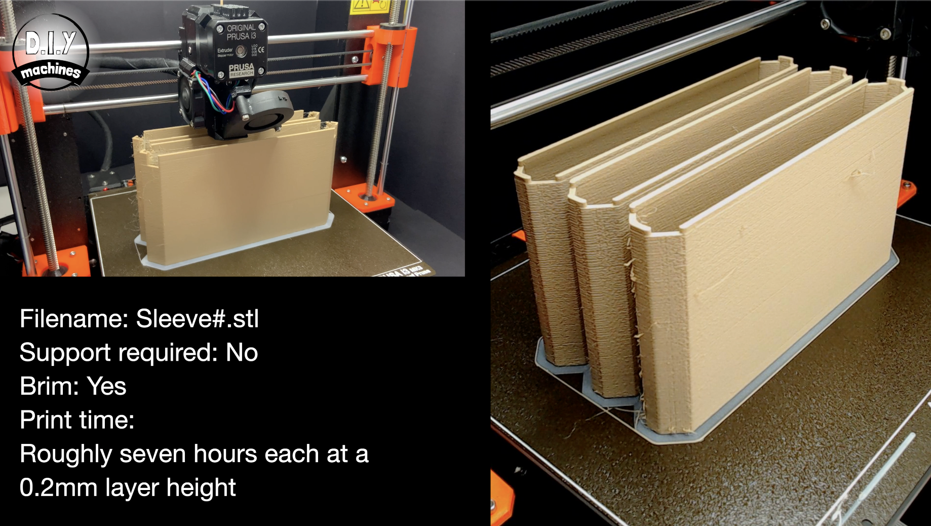
Let's take a break from electronics and turn back to 3D printing. There are five different styles of shelve sleeves to print depending on where they are going on the clock.
For every sleeve, I printed the first few layers in white and then switched to a wood infused PLA filament for the remainder of the print. This thin white front face is what allows the diffused light from the LEDs to shine through.
They took about seven hours each when printed at a 0.2mm layer height. U usually printed three at a time overnight. I also added a brim so as to help prevent them from becoming unstuck from the print bed. These are easily removed after the print is complete.
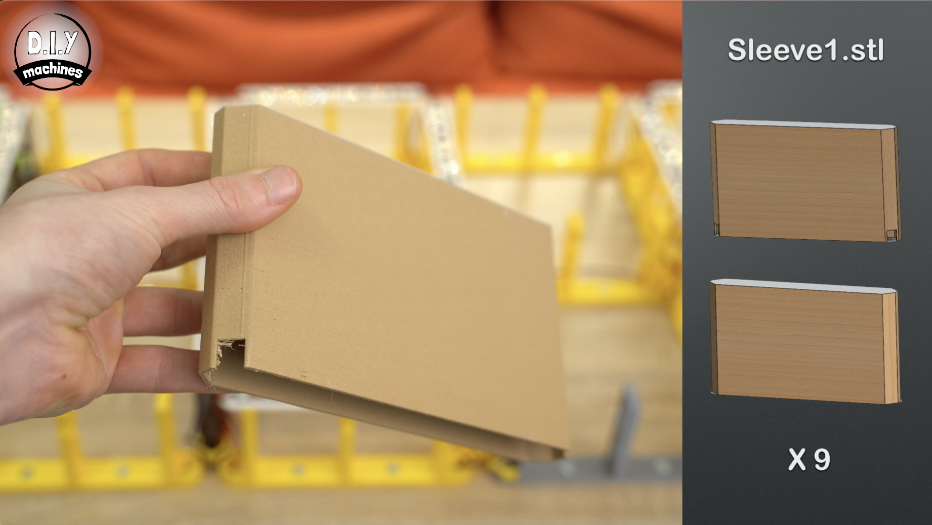
You need to print:
- 9x Sleeve1.stl - This one has cutouts on one side only.
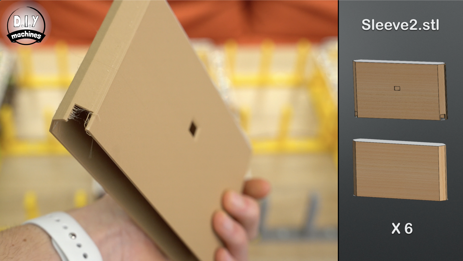
- 6x Sleeve2.stl - This has cutouts on one side and a hole for the LED downlighter.
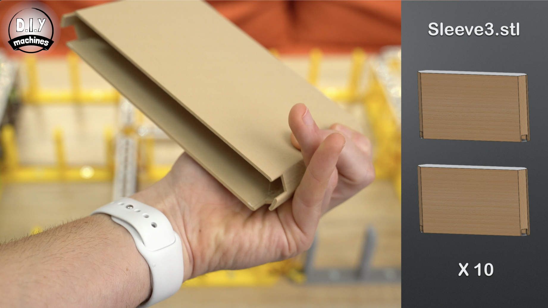
- 10x Sleeve3.stl - This has cutouts on both sides.
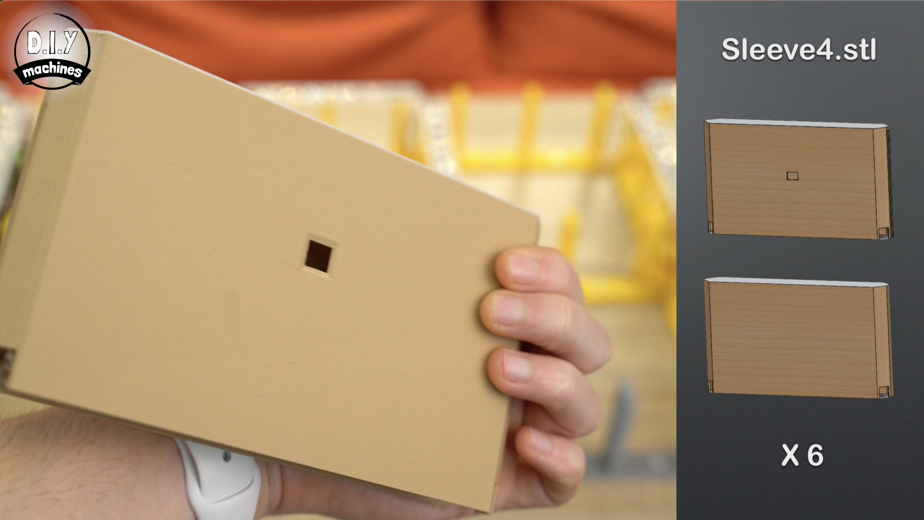
- 6x Sleeve4.st - This has cutouts on both sides and a hole for the LED downlighter.
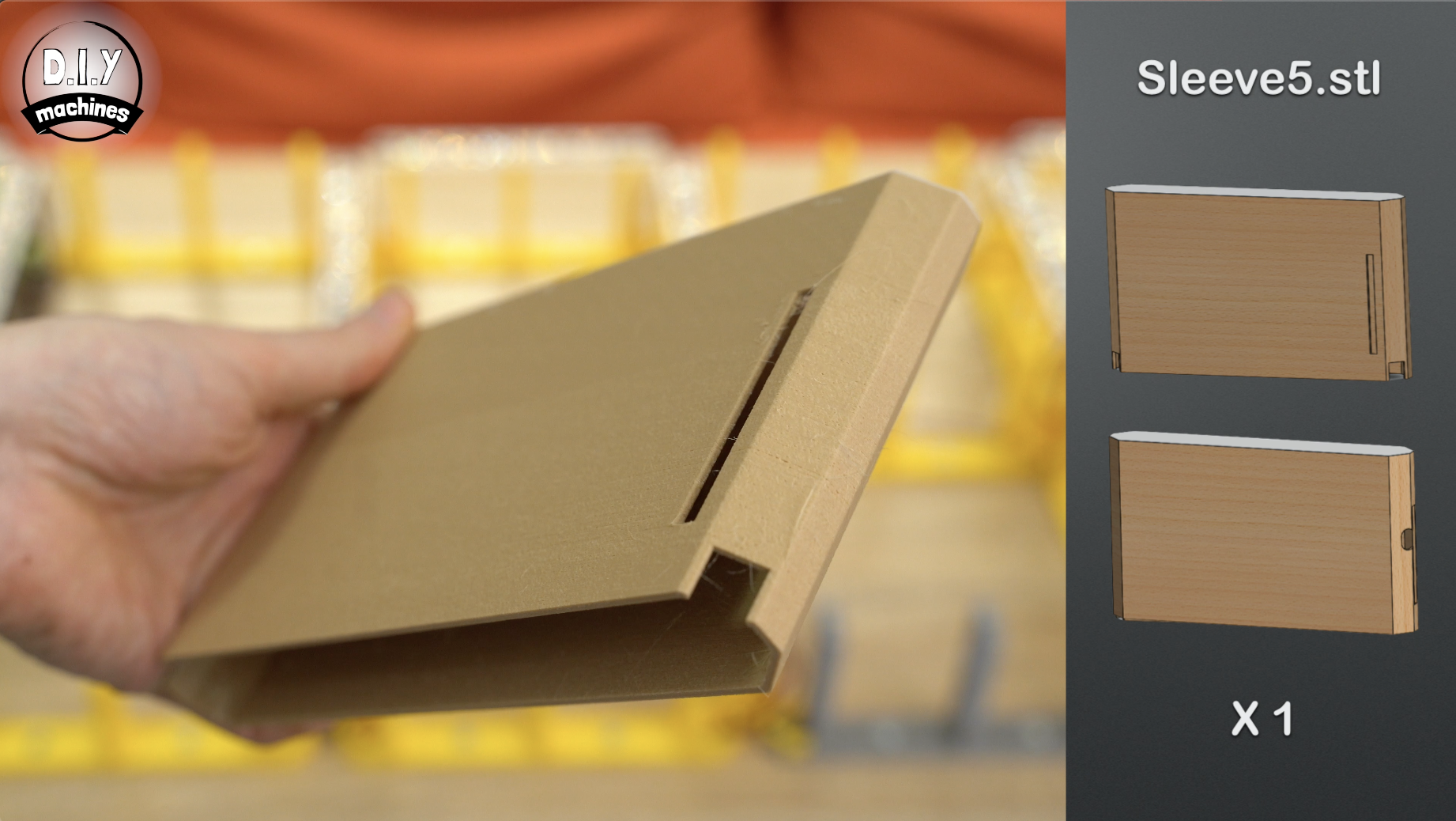
- 1x Sleeve5.stl - This one is specifically designed to house the electronics and includes air holes for ventilation and a hole for the photoresistor.
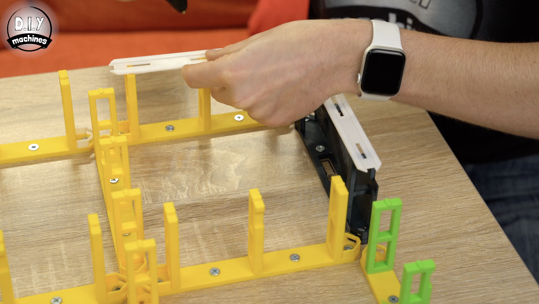
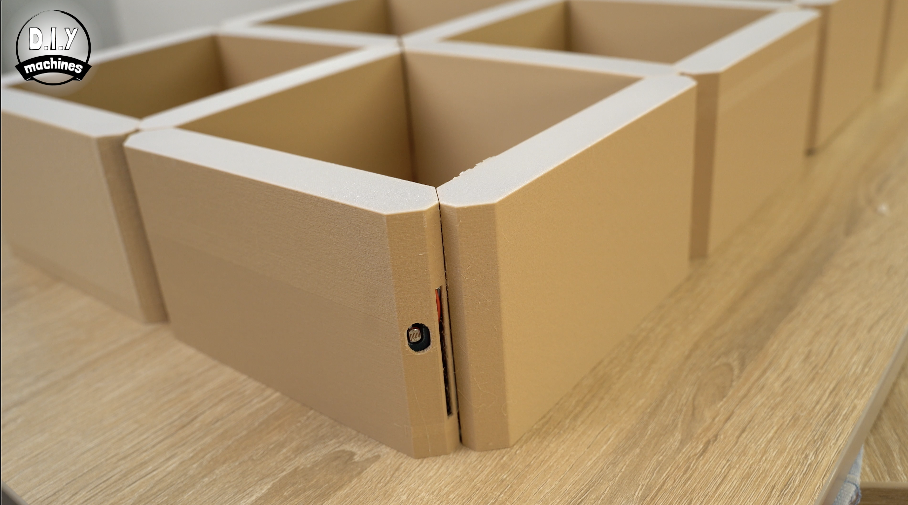
Step 13: Fitting the Shelve Sleeves
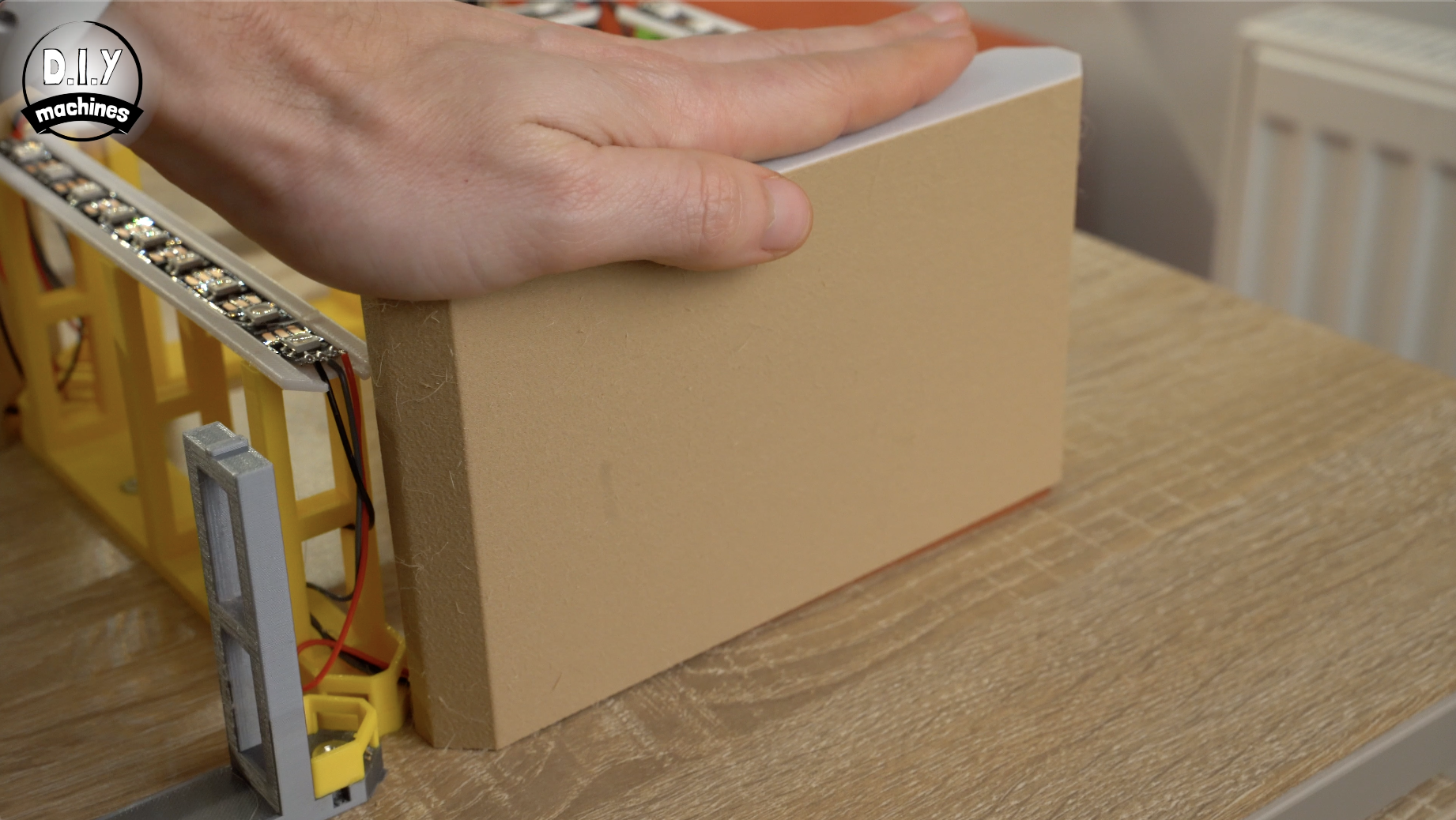
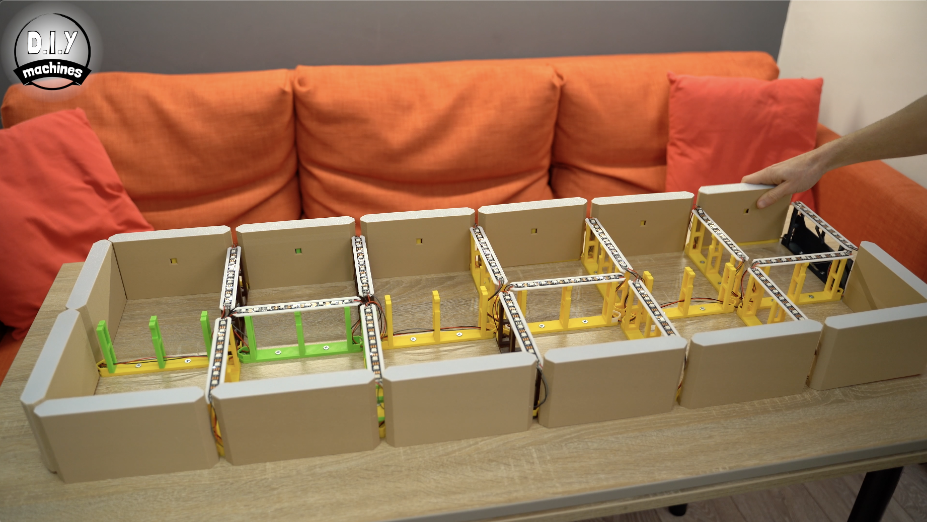
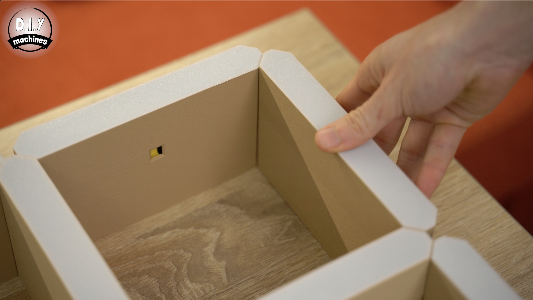
The shelves are installed by carefully sliding them over the supports and LEDs whilst making sure that the wires pass through the cutouts.
The nine Sleeve1's which you printed slide over the supports along the bottom and side of the clock (excluding the special electronics containing support) as shown in the above photo.
The six Sleeve2's all go along the top of the clock with the LED hole facing downwards.
The ten Sleeve3's go in the remaining vertical positions.
The six Sleeve4's fill in the horizontals running along the middle with the hole for the LED facing downwards again.
The last Sleeve5 goes over the remaining support in the top right.
Step 14: Connecting DS3231 to Arduino
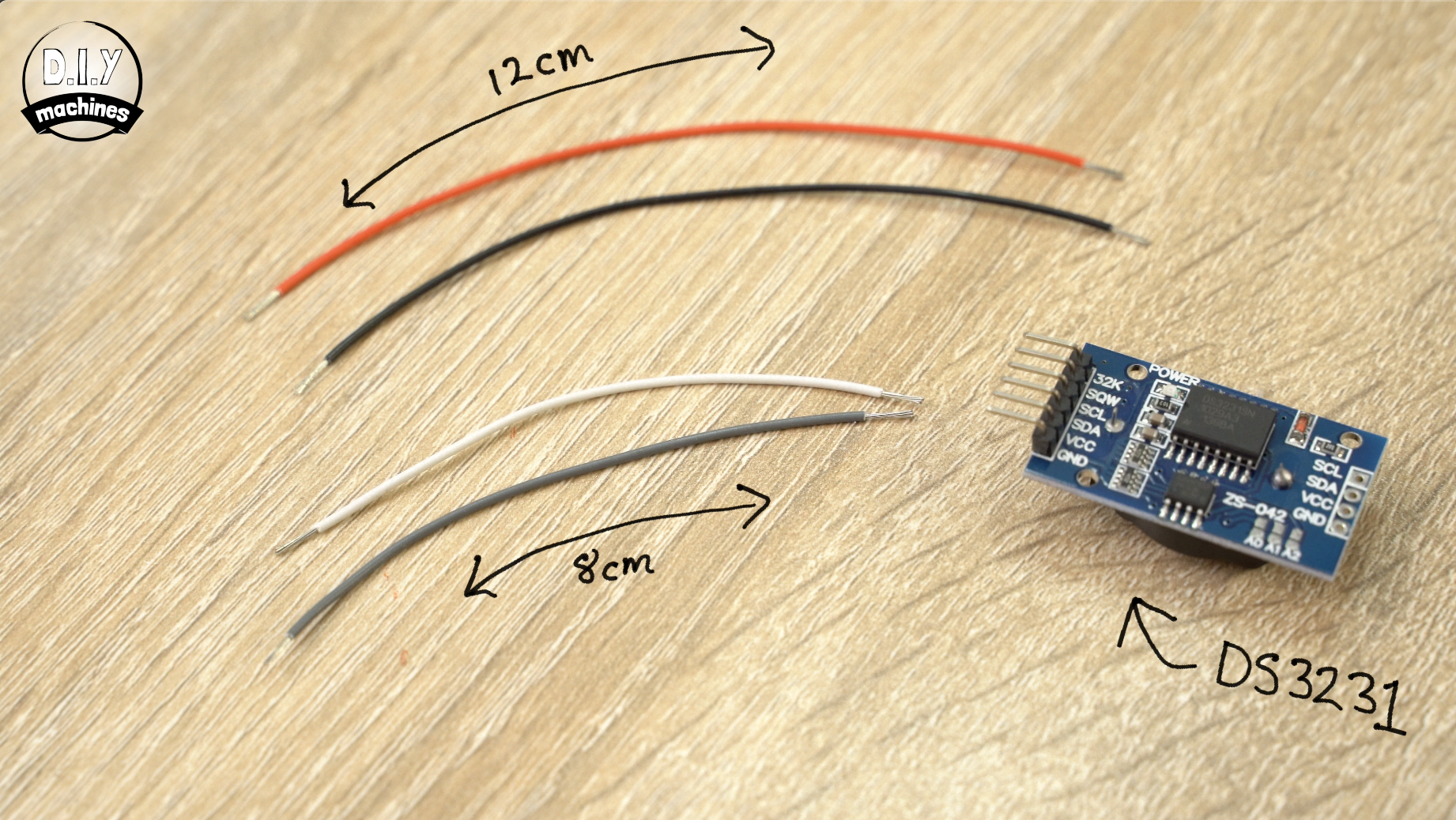
You will need to prepare the following for this step:
- A pair of 8cm wires
- A pair of 12 cm wires
- DS3231 - Real-Time clock (RTC)
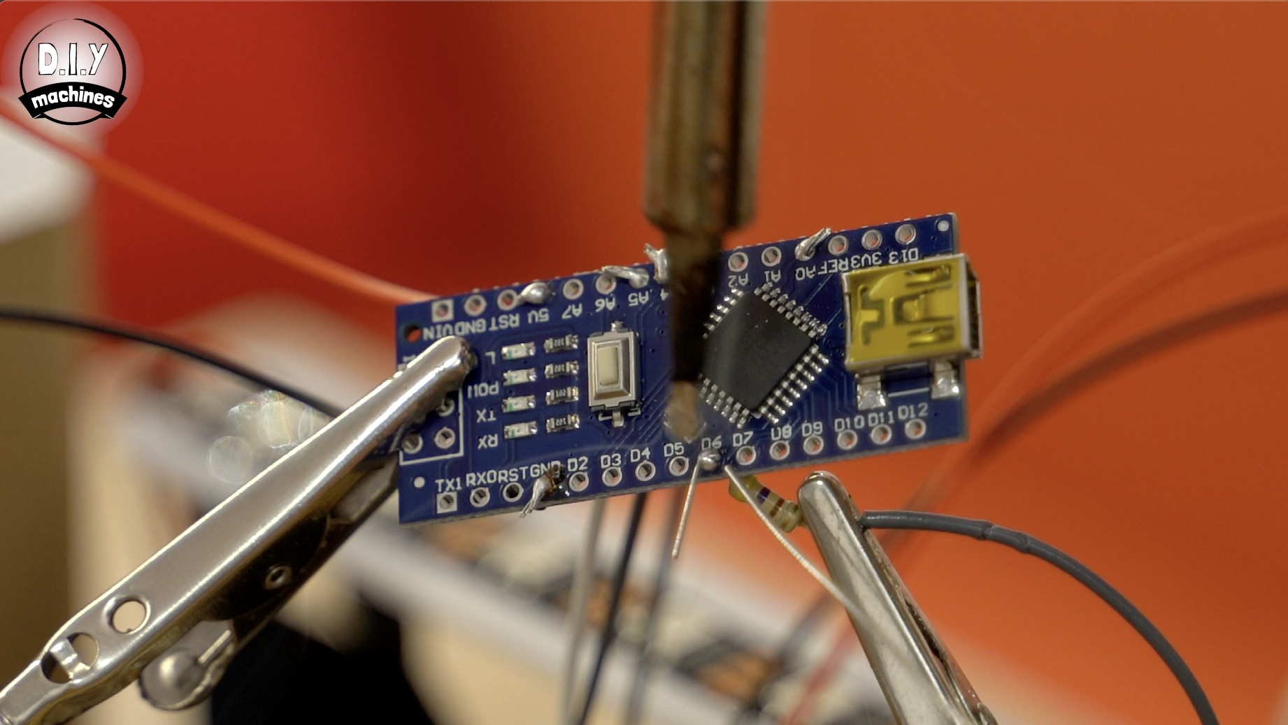
- Arduino Nano
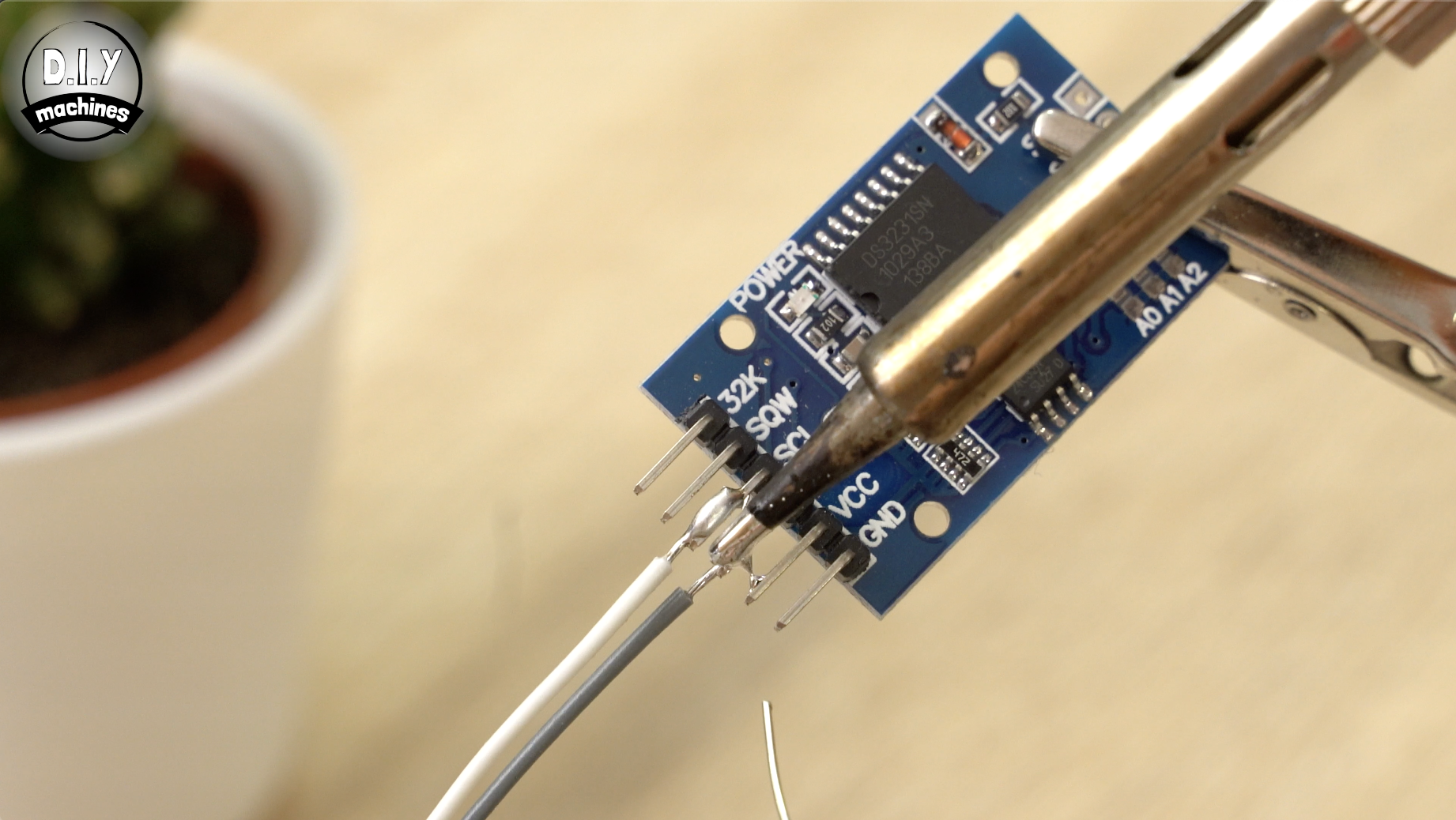
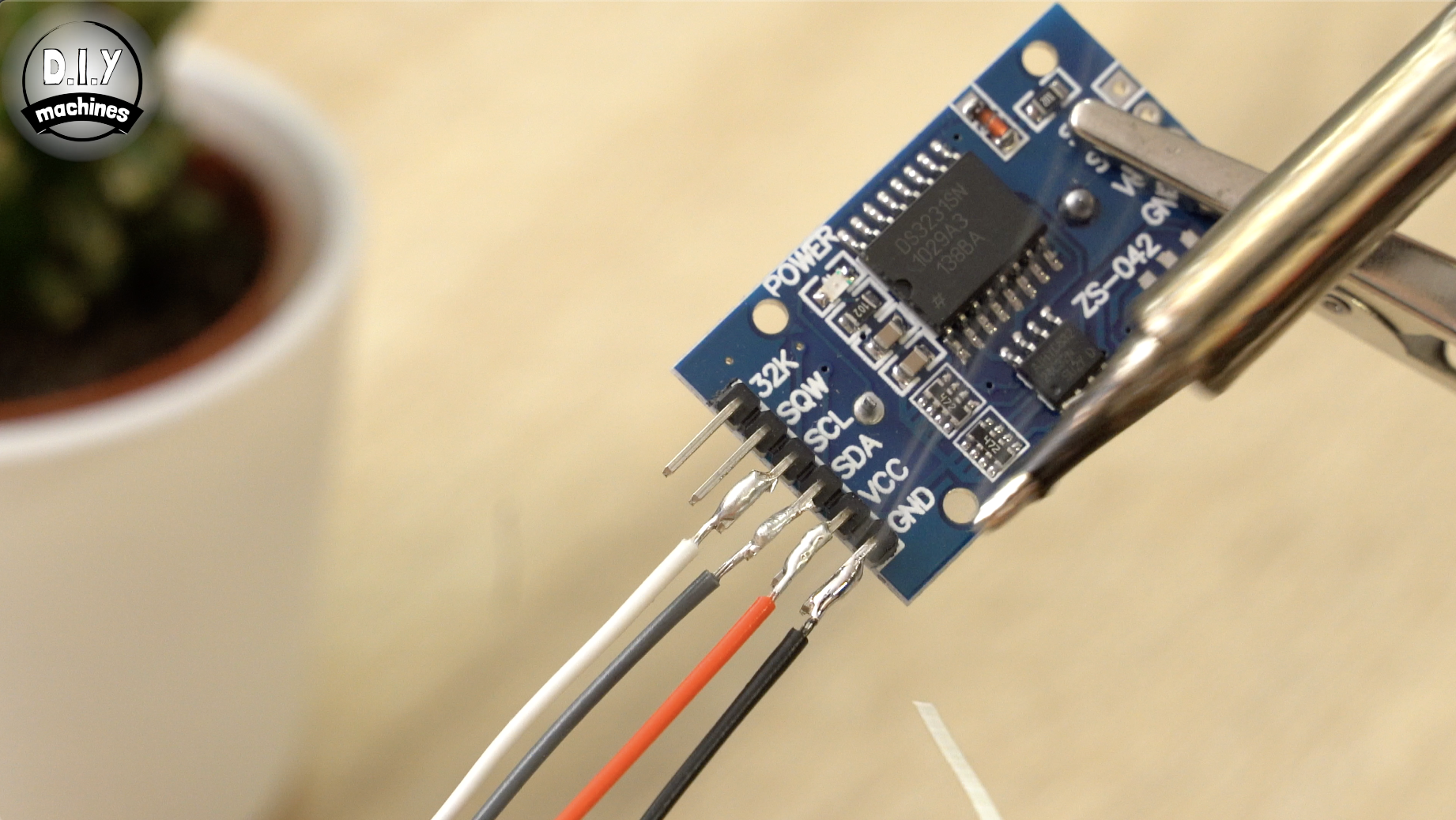
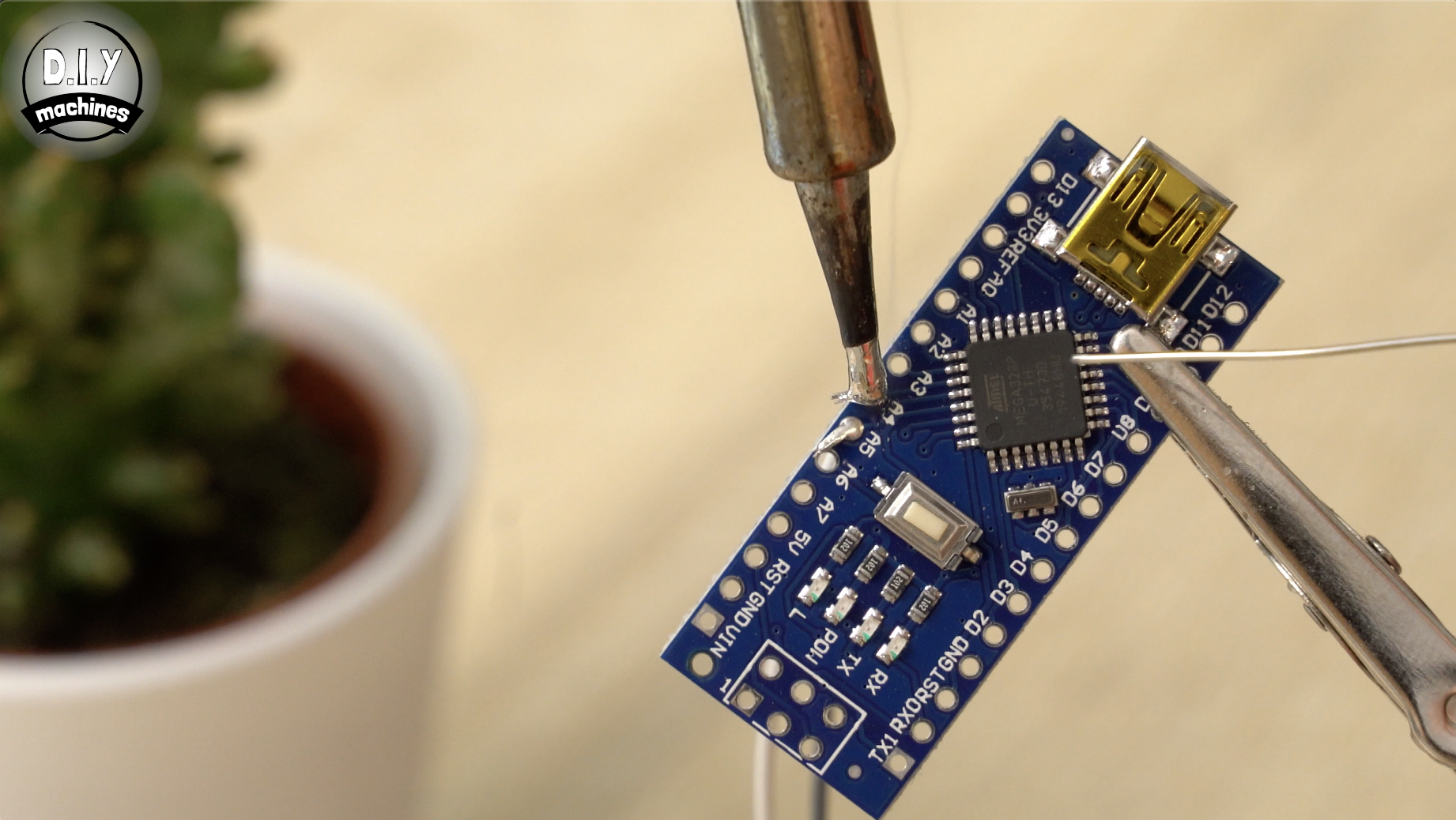
Start by soldering an 8cm wire to SCL and another wire to SDA on the RTC. Then solder a 12cm wire to VCC and another to GND (Ground). I'll be using red wires for the positive/VCC connections from now on and black wires for the ground/GND connections to help make it easier to understand what wire should be connected to what.
Taking the Arduino, solder the wire coming from SCL to A5 on the Arduino, then connect the wire from SDA to A4. We will be connecting the power wires later
Step 15: Connecting Photoresistor (light Sensor) to Arduino
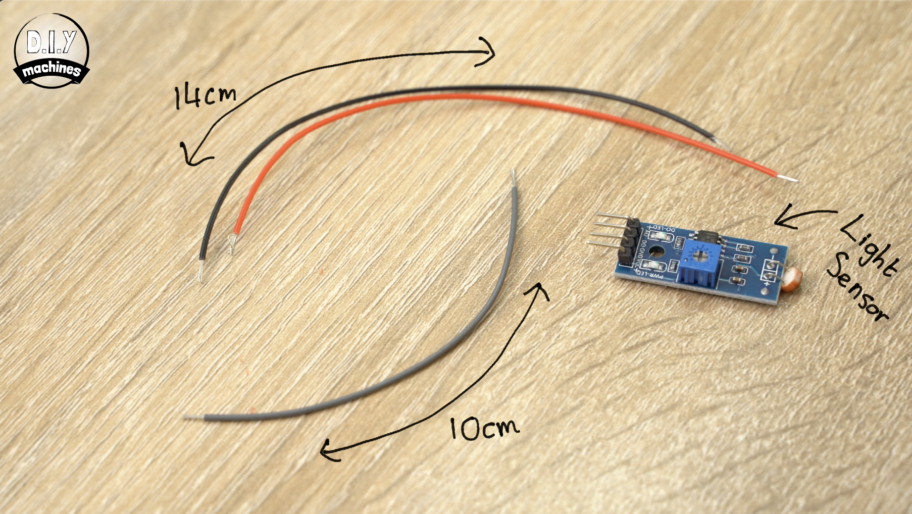
You will need the following for this step:
- Photoresistor module
- A single 10cm length of wire
- A pair of 14cm wires
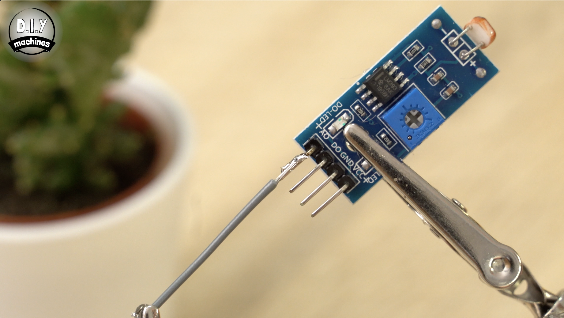
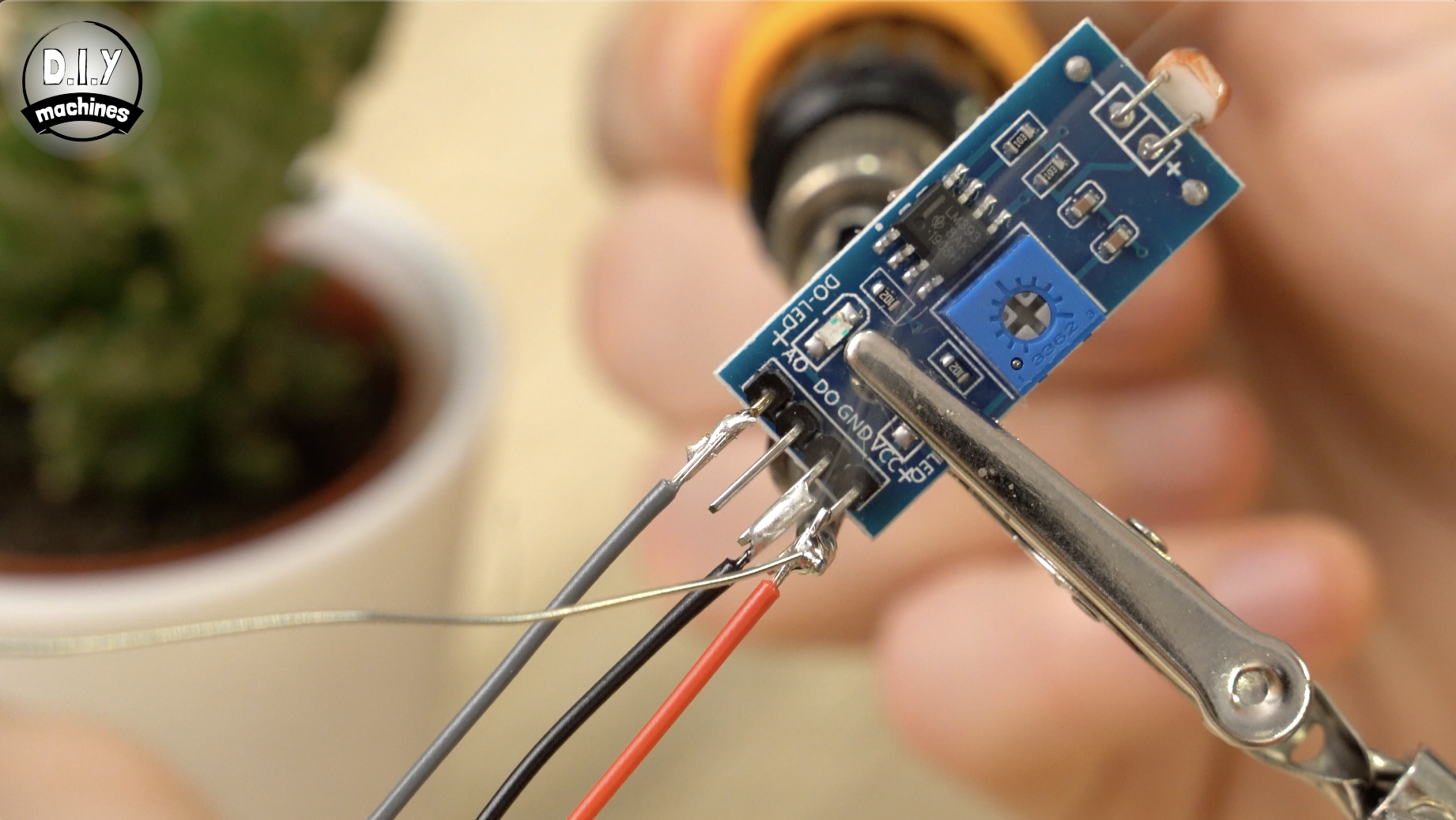
Solder the 10cm wire to AO on the module and each of the 14cm long wires to GND and VCC.
The 10cm AO wire is then connected to A0 on the Arduino Nano board. Again, we will be connecting the power wires later.
Step 16: Prepare the Nano to Connect to Power
For this step prepare:
- Two 12cm lengths of wire.
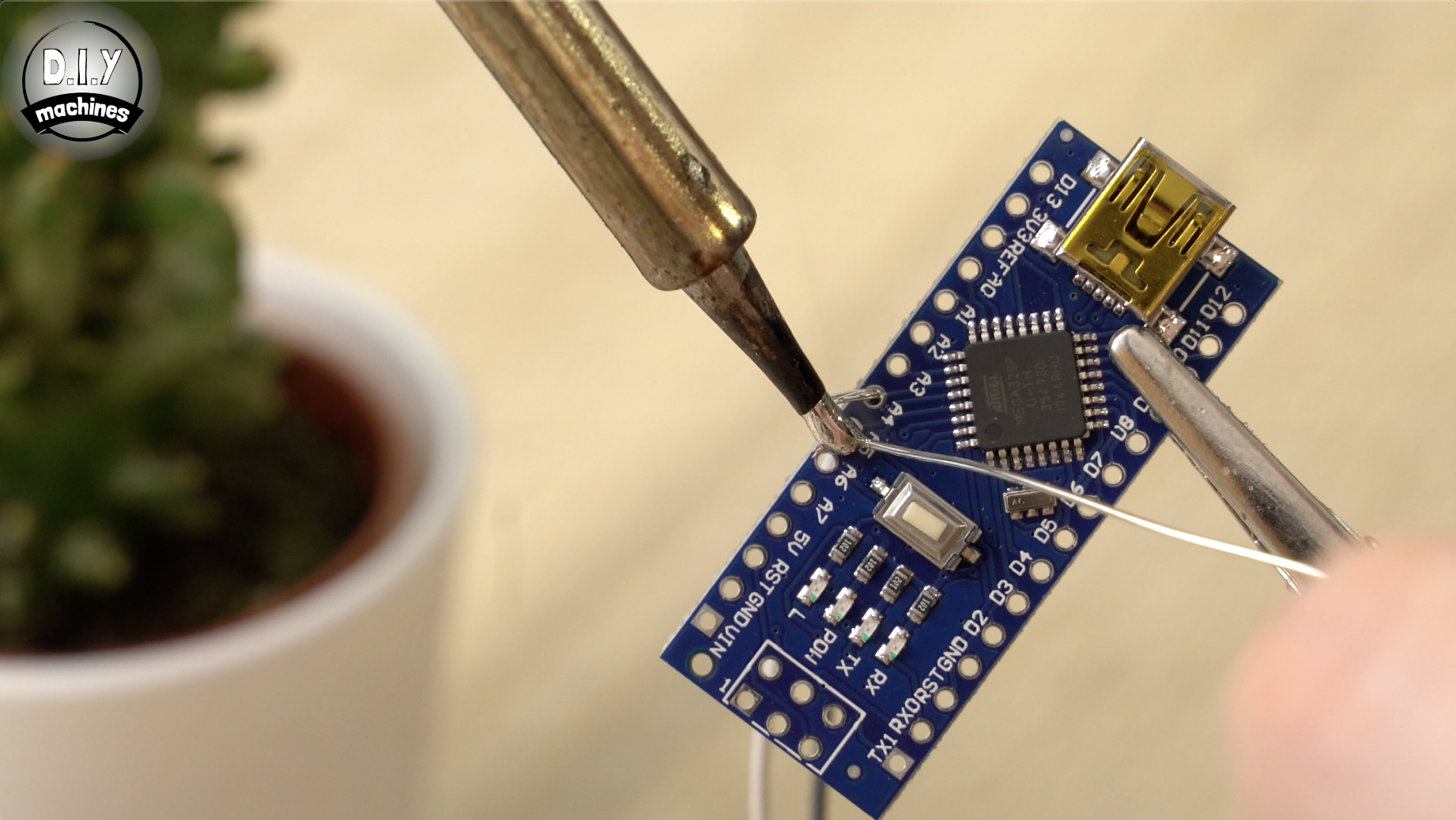
Solder one of the wires to any of the GND connections on the Arduino and the other wire to the 5V pin.
Step 17: Connect the LEDs
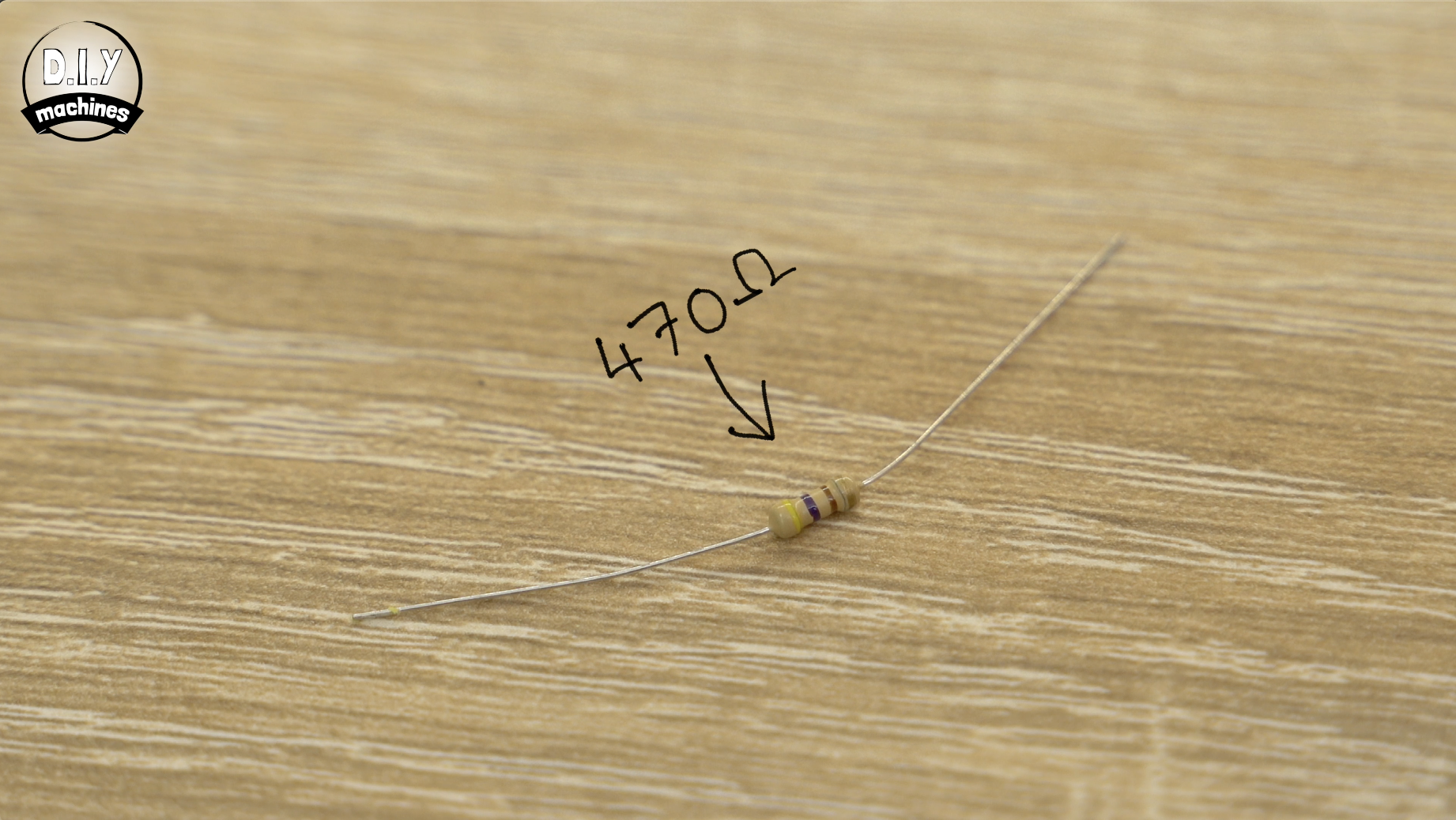
You will need:
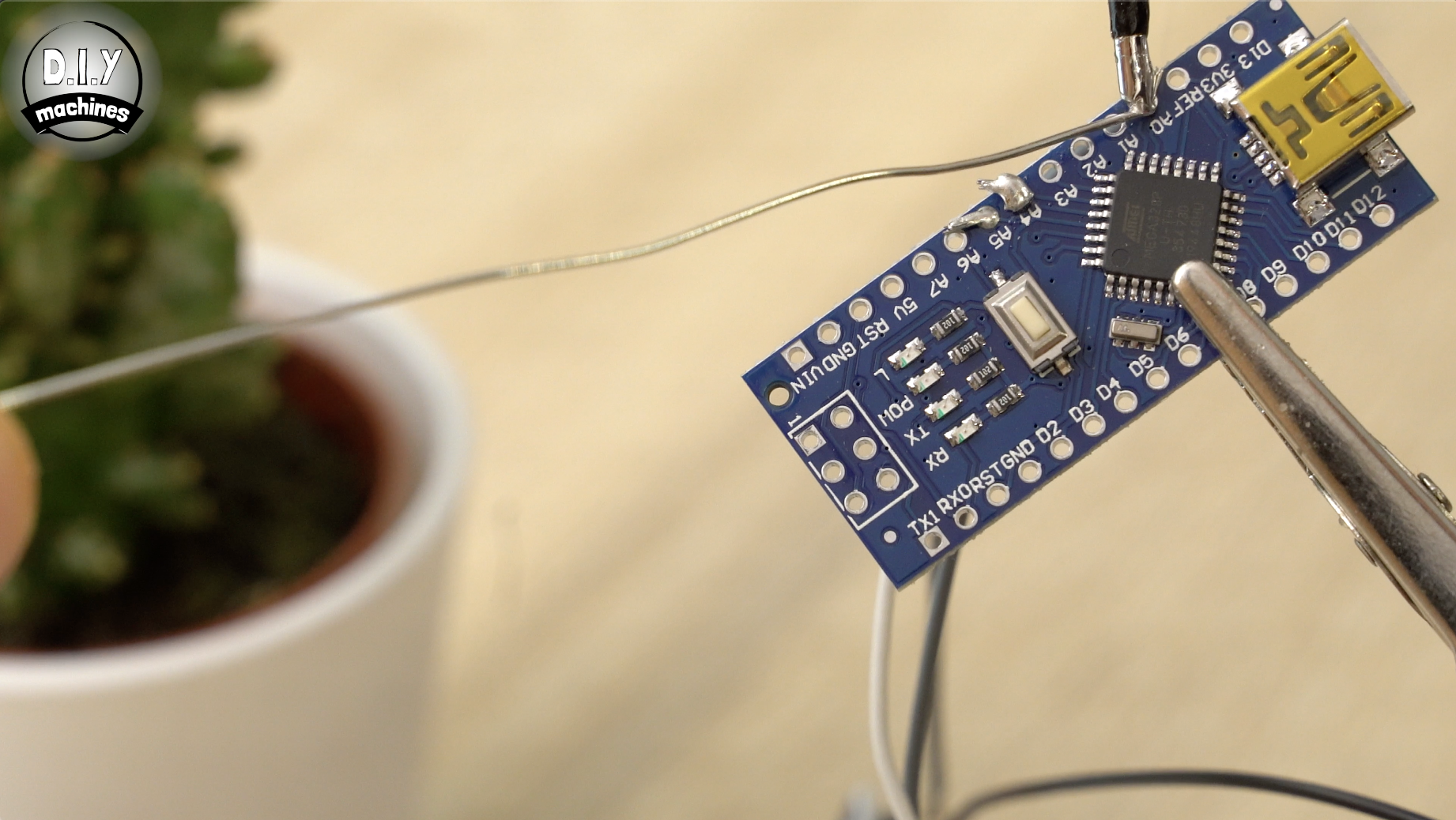
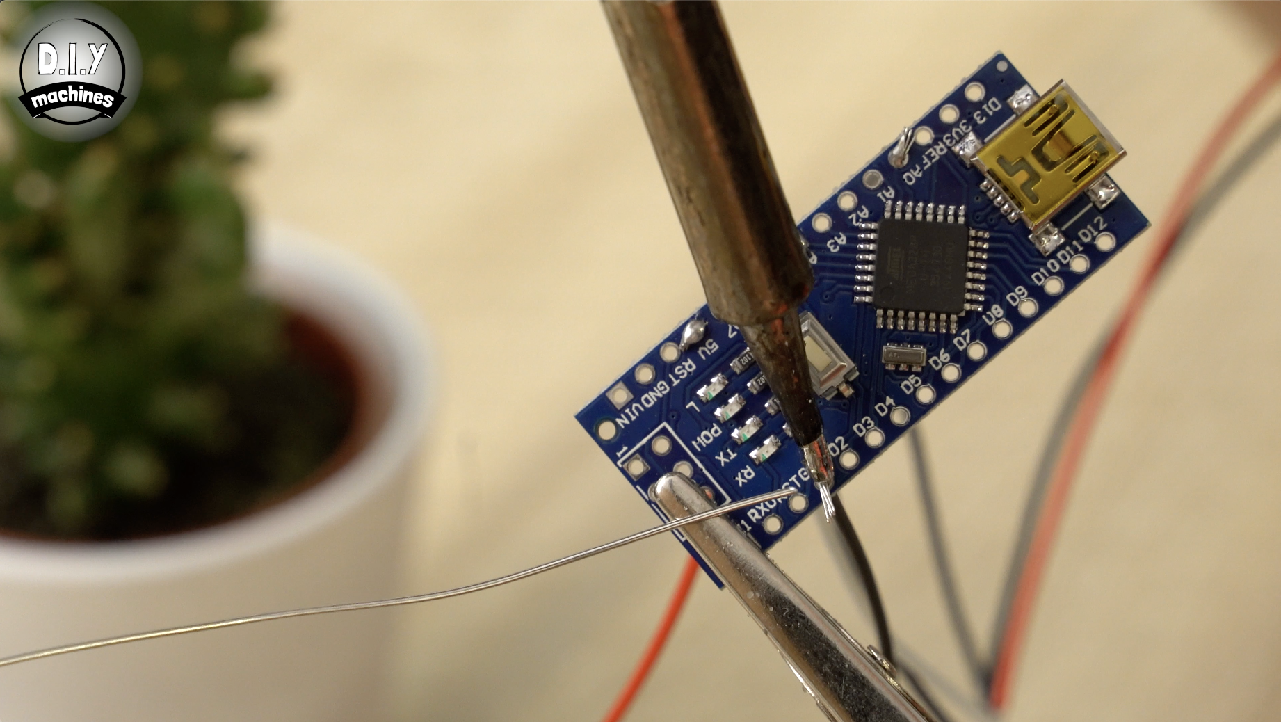
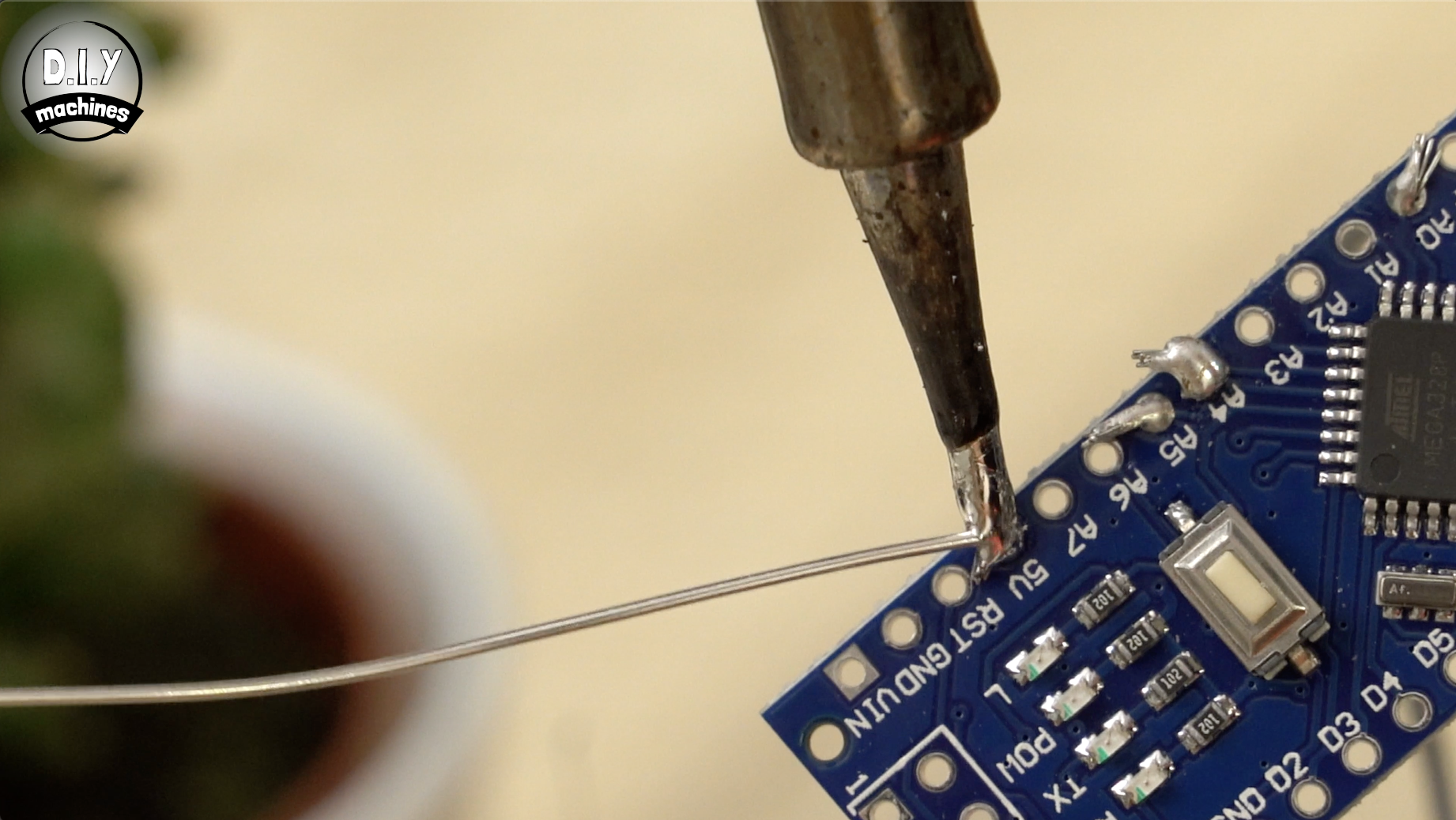
- One 470 ohm resistor.
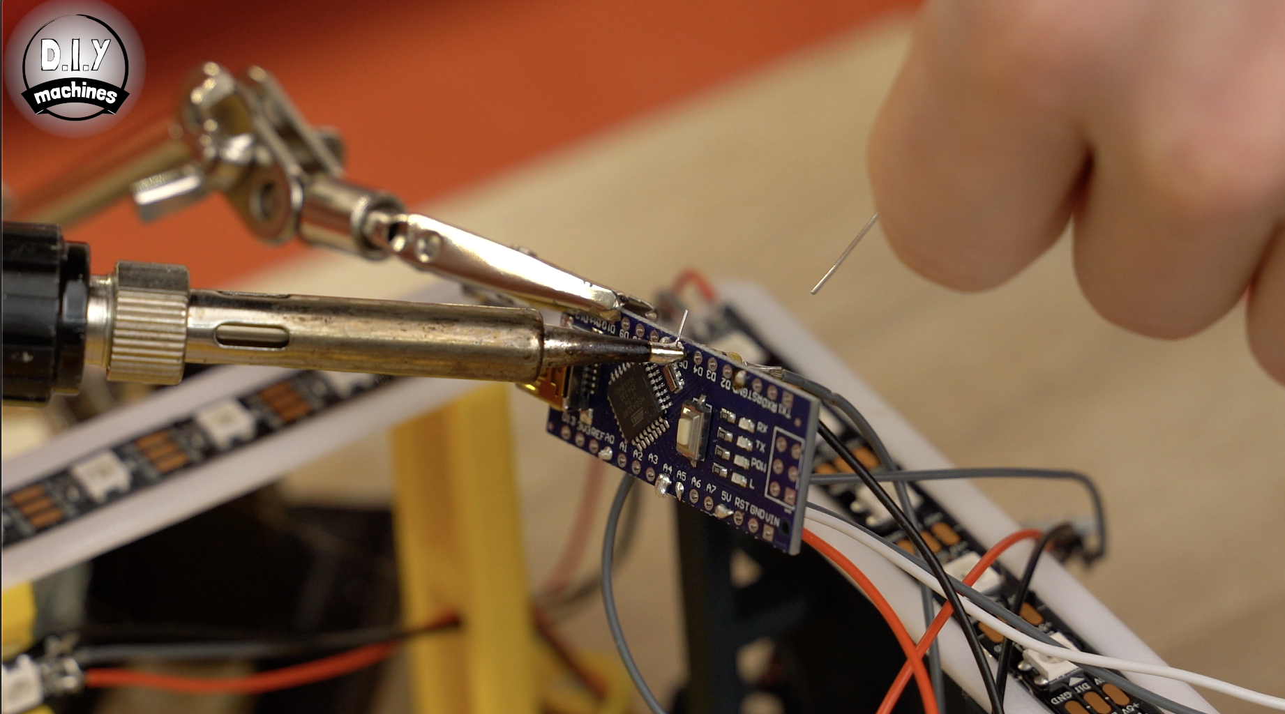
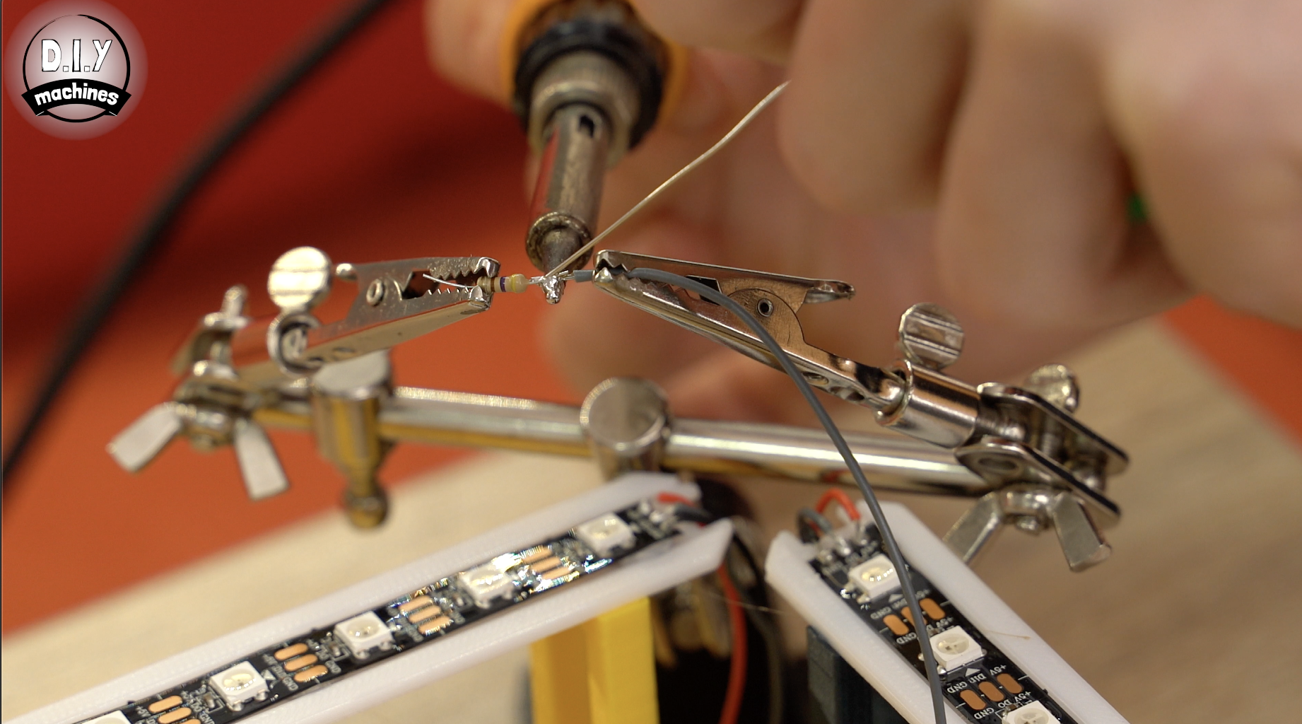
Shorten the legs on the resistor slightly as they are much longer than required. Solder one side of the resistor to the wire which is already connected to DIN on the ingoing side of the first LED strip we installed. This is the one over the 3D printed support designed to house all the electronics.
The other end of the resistor is then soldered to D6 on the Arduino.
Step 18: Power Warning...
A quick warning to share with you. Don't connect the mains power supply at the same time you are using the Arduinos USB connection. You risk damaging whichever device is connected to your Arduino. This is why we have not connected the mains power yet and will not be doing so until the project is complete and we no longer need to connect via USB.
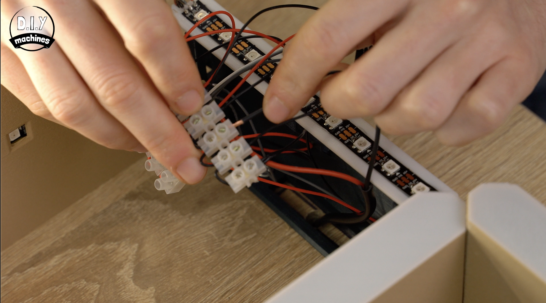
Step 19: Connecting the Power Wires
For this step you'll want:
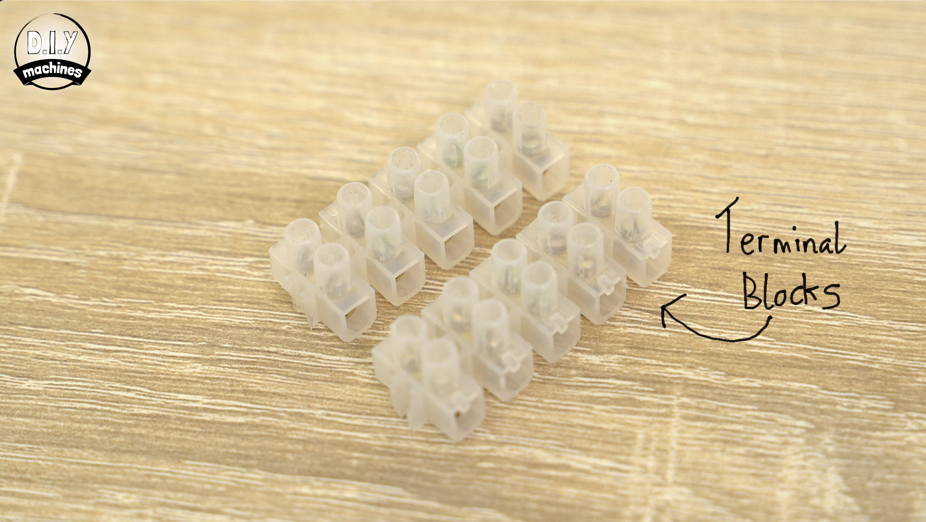
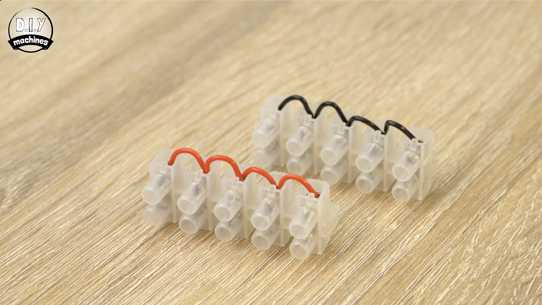
- Your two strips of terminal blocks
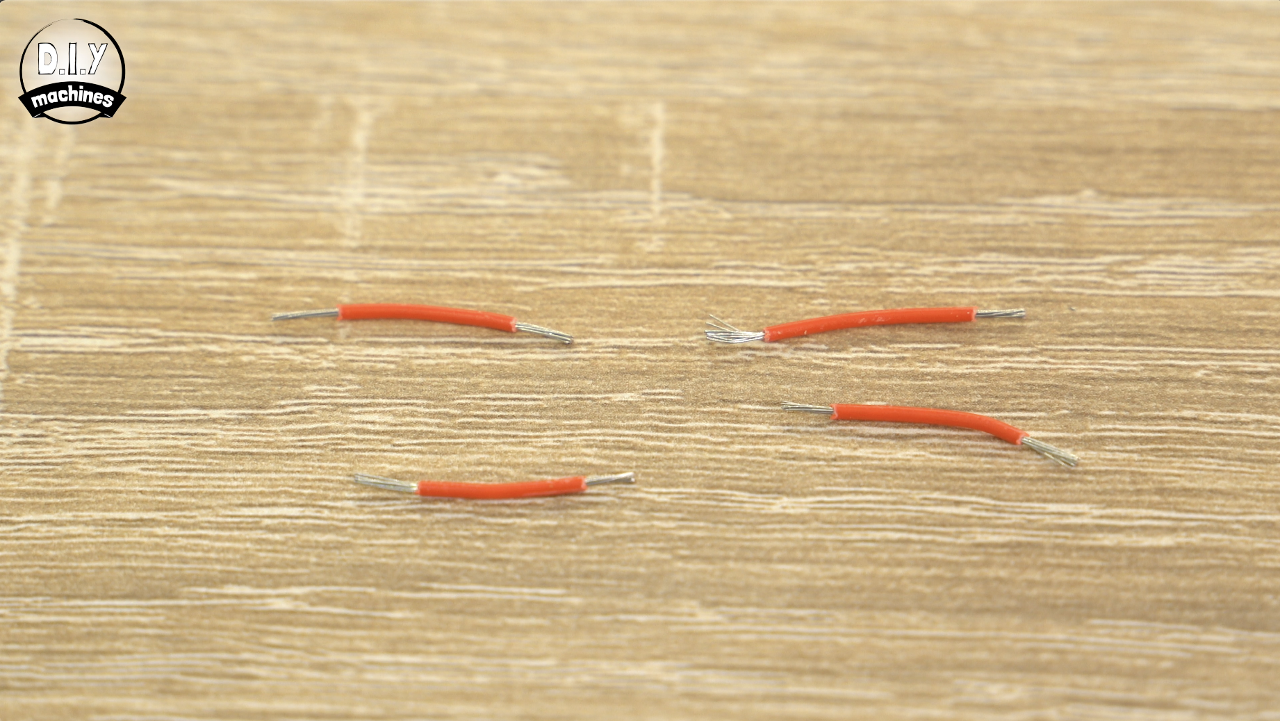
- 8 short lengths of wire (I did four in red and four in black)
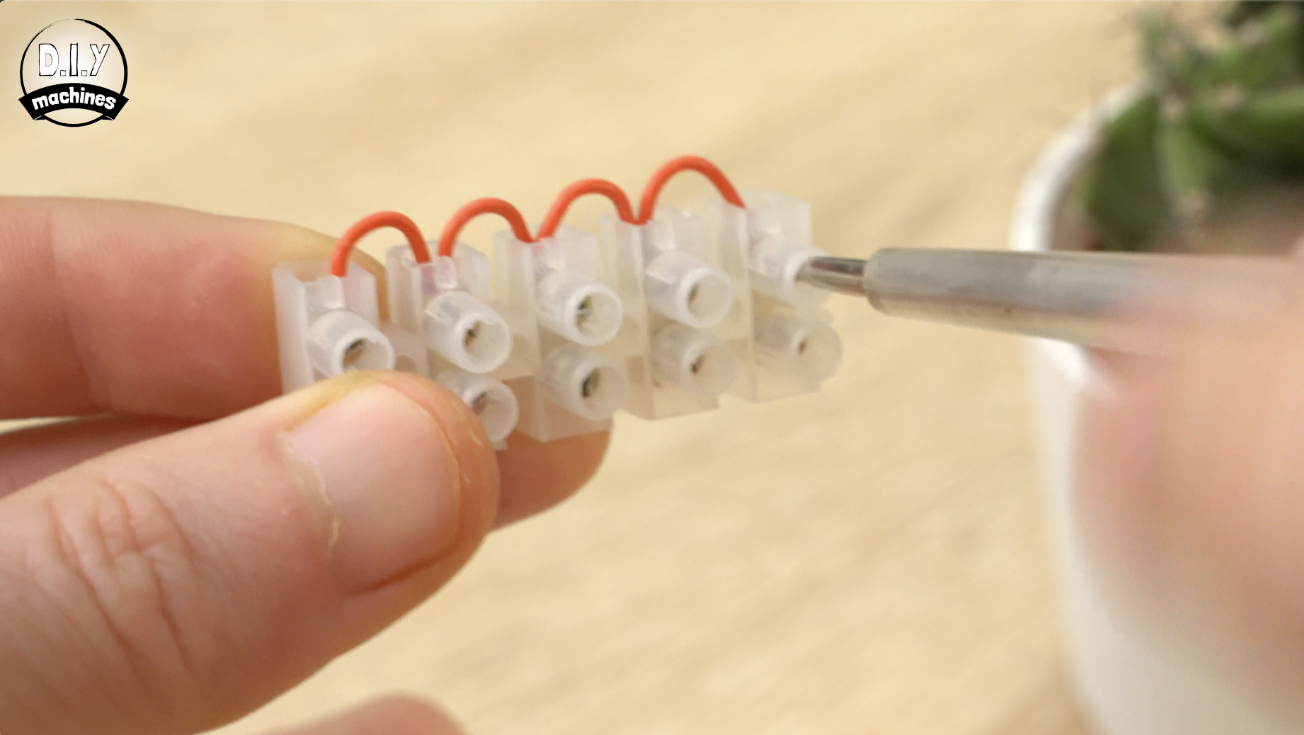
Use each short length of wire along one side of the terminal block to as jumper wires to connect them all together. Once you have screwed them into the terminal blocks, tug on them to ensure they are held well by the screw. Repeat this for both terminal strips.
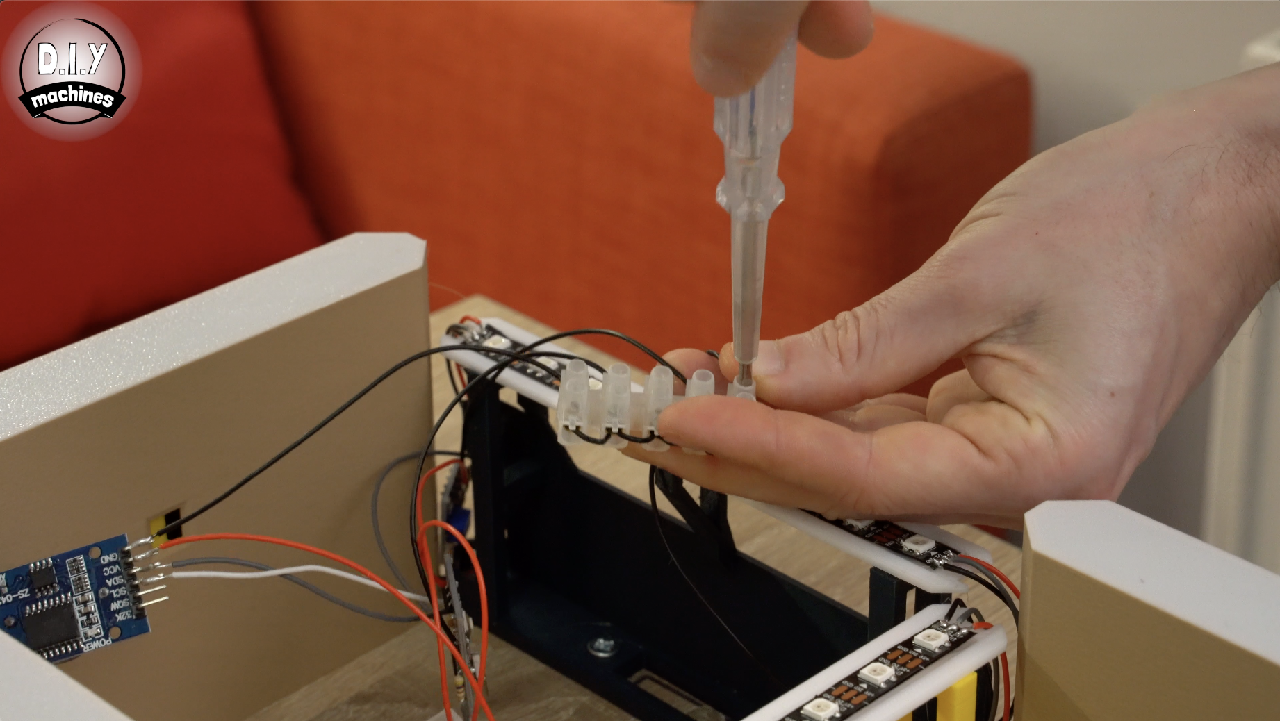
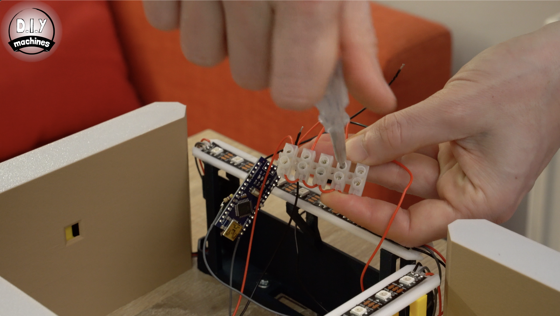
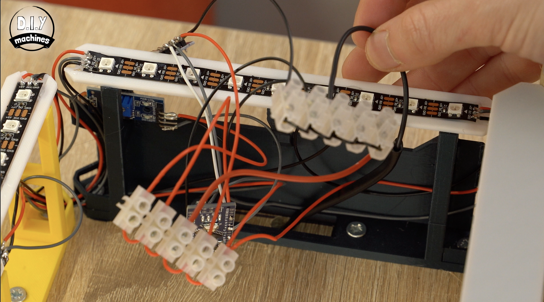
Now we can take all the VCC/5V wires going to our components and connect them to the same terminal block strip. Then do the same for all the GND/Ground wires with the other terminal block strip.
You should find them coming from each of the following components:
- Arduino
- First LED strip
- DS3231
- Photoresistor
Step 20: Uploading the Code
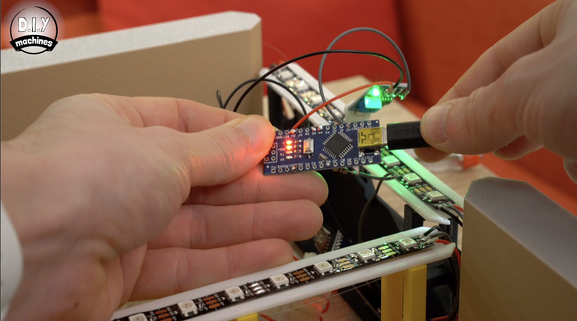
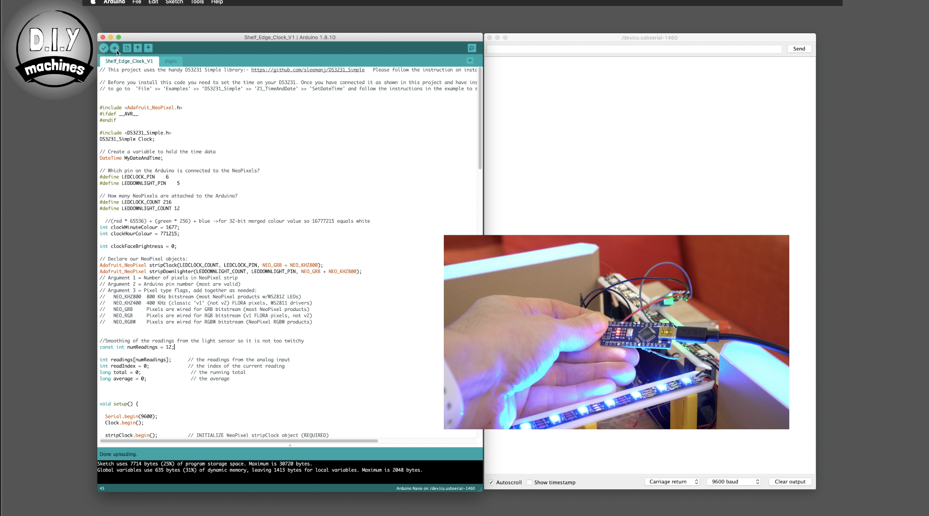
Connect your Arduino to your PC via its USB connection and open up the code for this project in the Arduino IDE. You can download the code from Github: https://github.com/DIY-Machines/DigitalClockSmart...
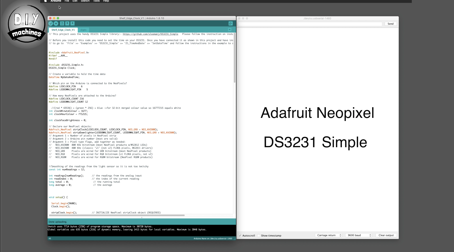
You need to have two different libraries installed in your Arduino IDE for this project; 'Adafruit Neopixel' and 'DS3231 Simple'.
If you do not already have them you will need to install them.
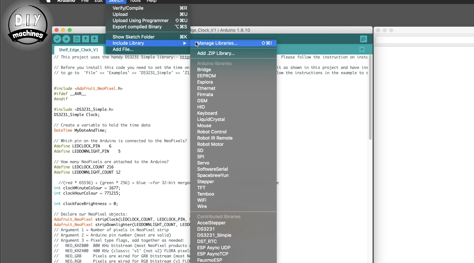
To install the Adafruit library:
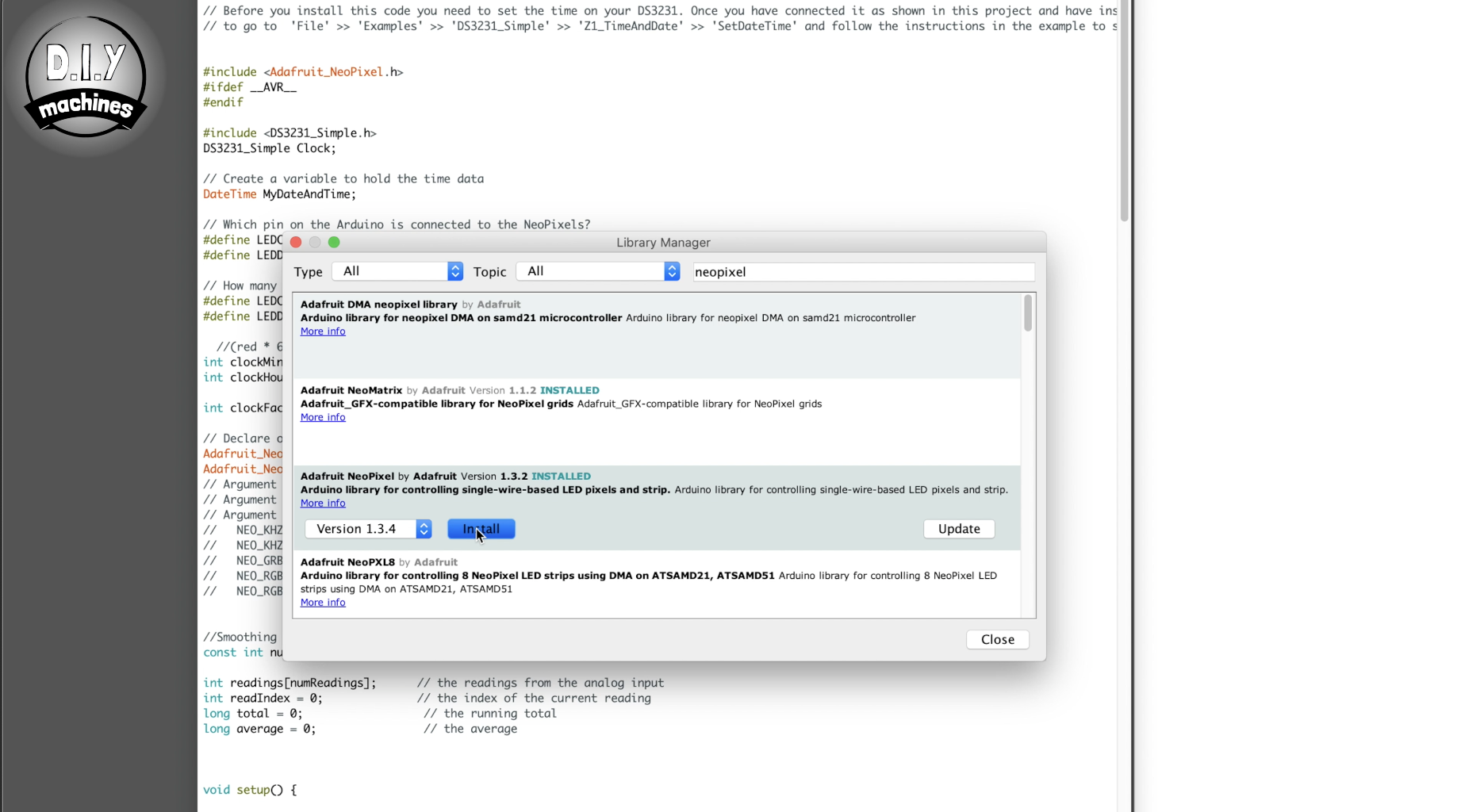
In the Arduino IDE, navigate to Sketch > Include Library > Manage Libraries Then in the Library Manager search for Neopixel strip using the search bar. Press install.
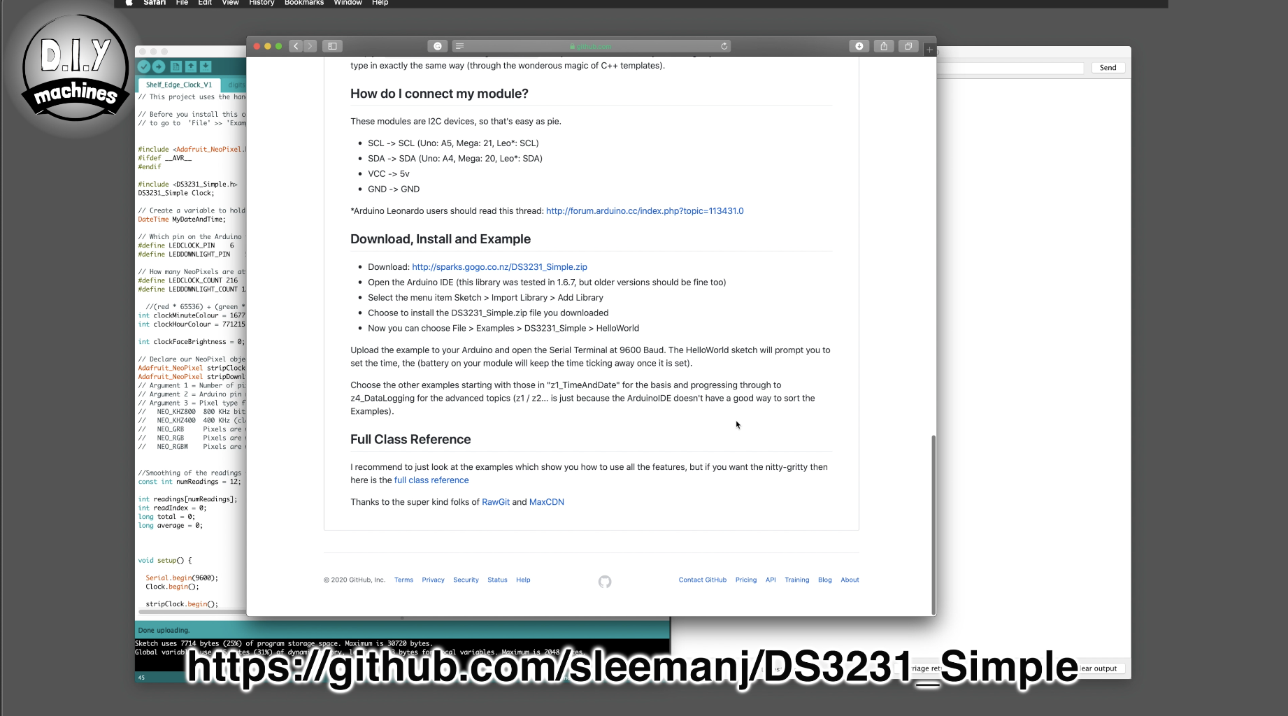
For the DS3231 library head to https://github.com/sleemanj/DS3231_Simple and follow the simple instructions on the page.
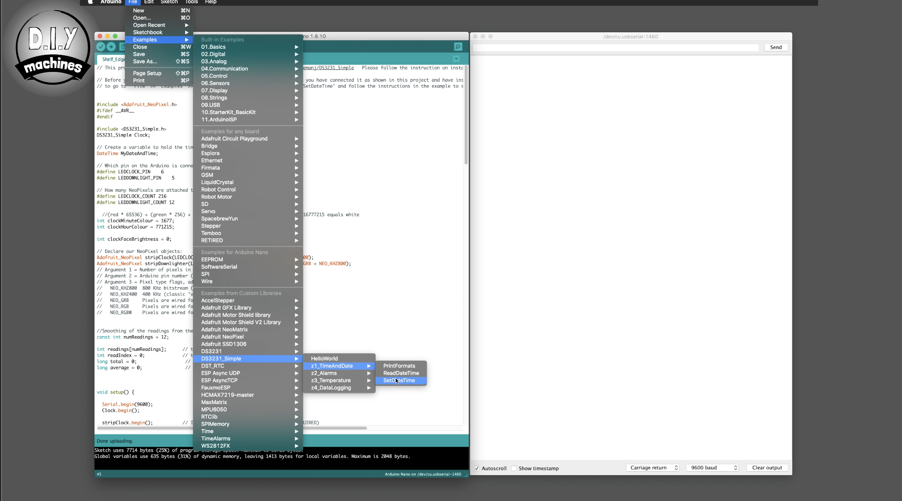
We can first set the time on the clock by running a small script provided by the author of the library. We only have to run it once. To do this head to ‘File' >> 'Examples' >> 'DS3231_Simple' >> 'Z1_TimeAndDate' >> 'SetDateTime' set the date and time you want and then upload it to your Arduino. This will set the correct time on your RTC which will persist when the Arduino loses power for as long as the button battery lasts. This window can now be closed and the main project script uploaded in its place.
If everything has gone as it should so far your clock face should spring into life and light up the current time.
Step 21: Adding the LED Down Lighters
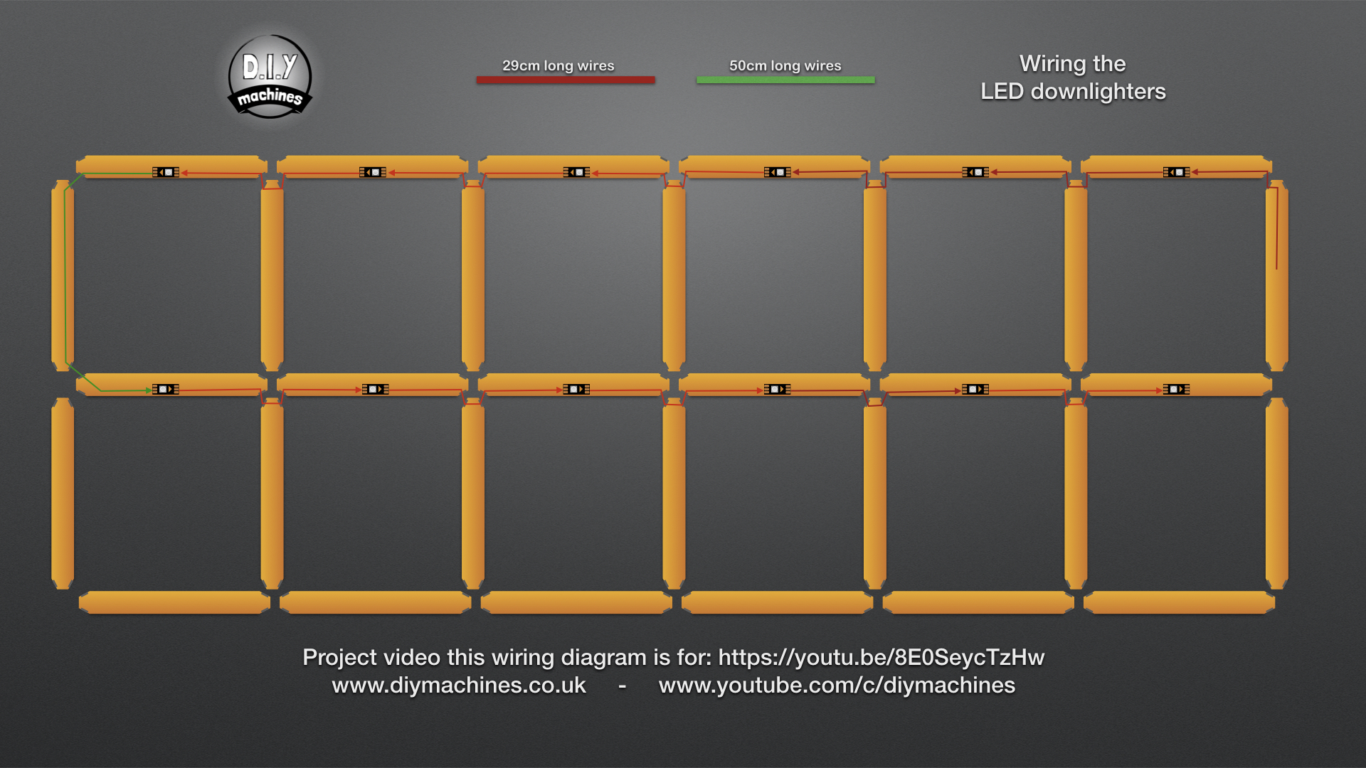
For the LED downlighters you will need to prepare the following:
- 11 sets of 29cm long wires
- One set which is 48cms long
- 12 individual LEDs cut from the roll we were using earlier
- A 470 Ohms resistor
Don't forget that tinning the pads on the LEDs and the ends of the wires will make soldering them together much easier later.
The 3D printed sleeves for the top half and centre row of the clock will need to be removed so that we may install the wiring for the downlighters. To remove them just carefully pull them straight upwards.
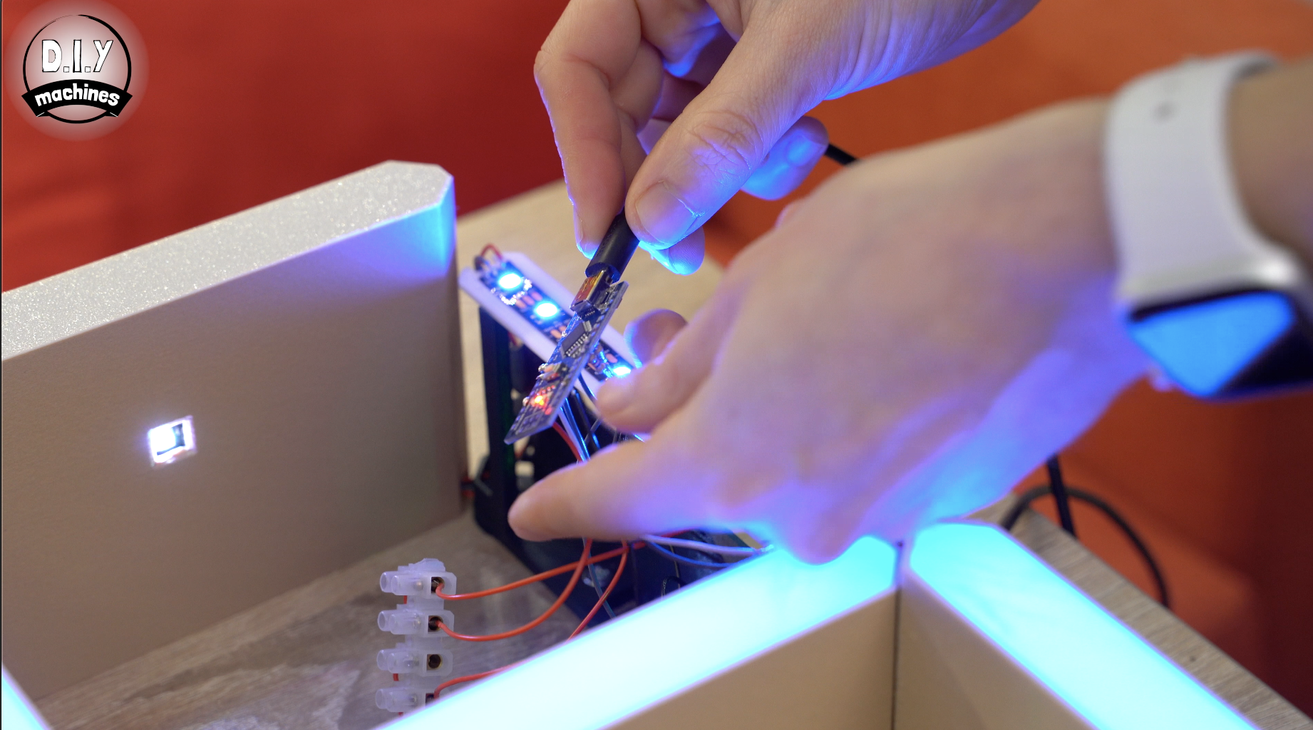
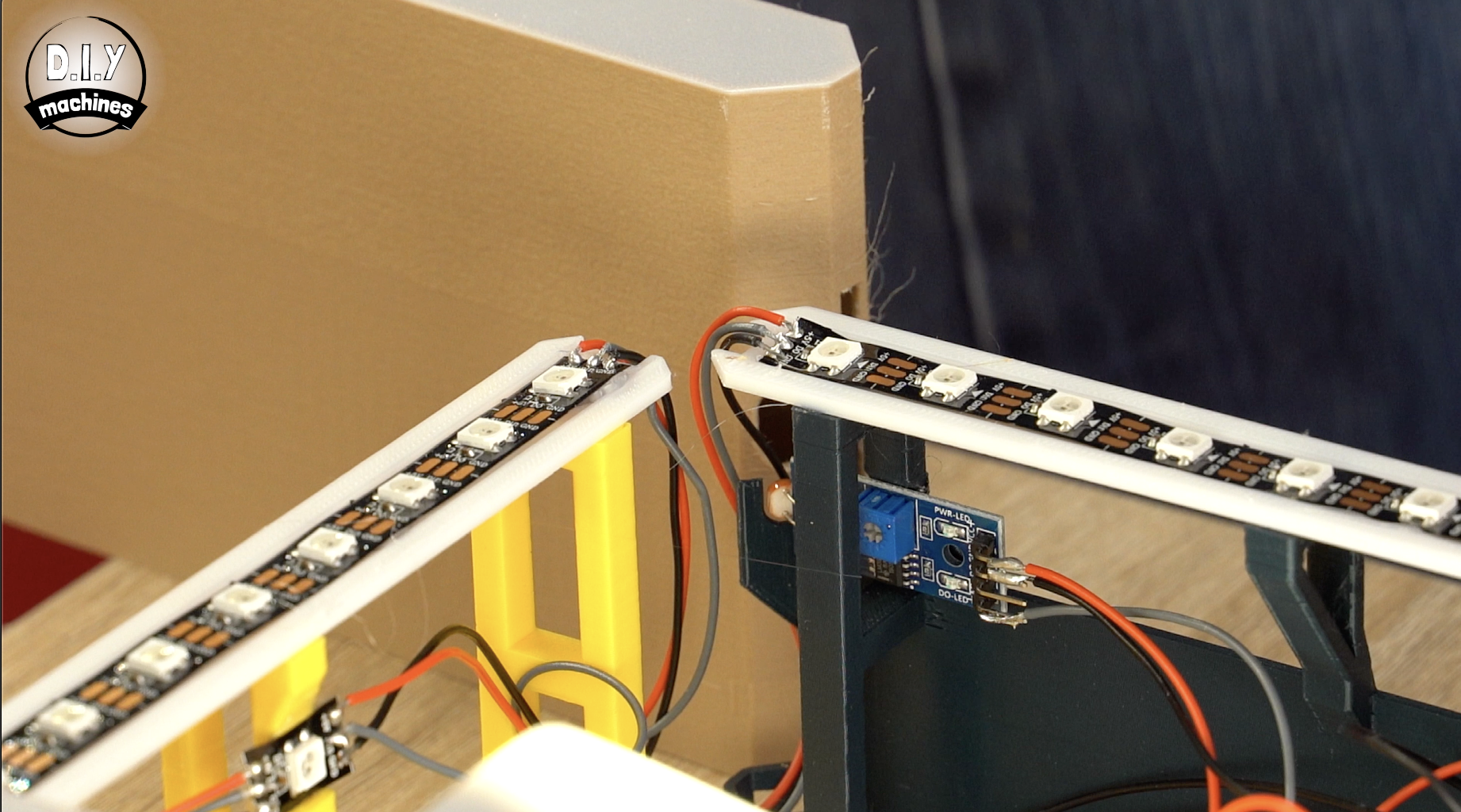
The first LED downlighter will be fitted to the horizontal support at the top right of the clock face. Solder a set of 29cm long wires to both sides of one of the individual LEDs and then glue this into place in the notch on the centre support column. You still need to pay attention to the direction of data flow, and for the top row of LED downlighters it should be facing away from the Arduino as highlighted in the image.
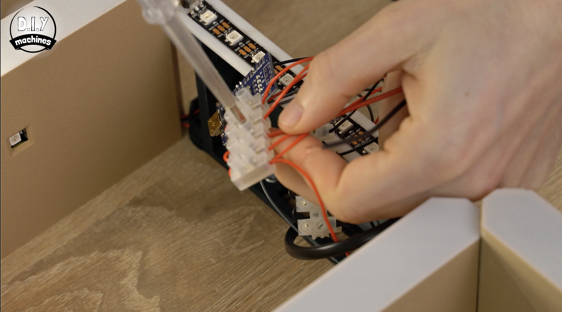
You can then thread the wires through the wire guides at both ends of the support. Solder a 470 Ohms resistor the DIN cable which is on the Arduino side of the LED. The other end of the resistor is then connected to D5 on the Arduino.
The VCC and GND connection going to the LED can then be added to the appropriate terminal block strips.
Continue adding the LED downlighters along the top row using the 29cm sets of wires between each one. At the end of the row (6th LED) attach the 48cm set of wires so we reach down to the next row and then carry on adding LEDs with 29cm long wires between them.
I created a diagram that is attached above which makes it clear which wires to use between the LEDs, which way the data arrow must be facing and how to route the wires through the wire guides at the base of the 3D printed core supports.
Step 22: Test the Downlighters

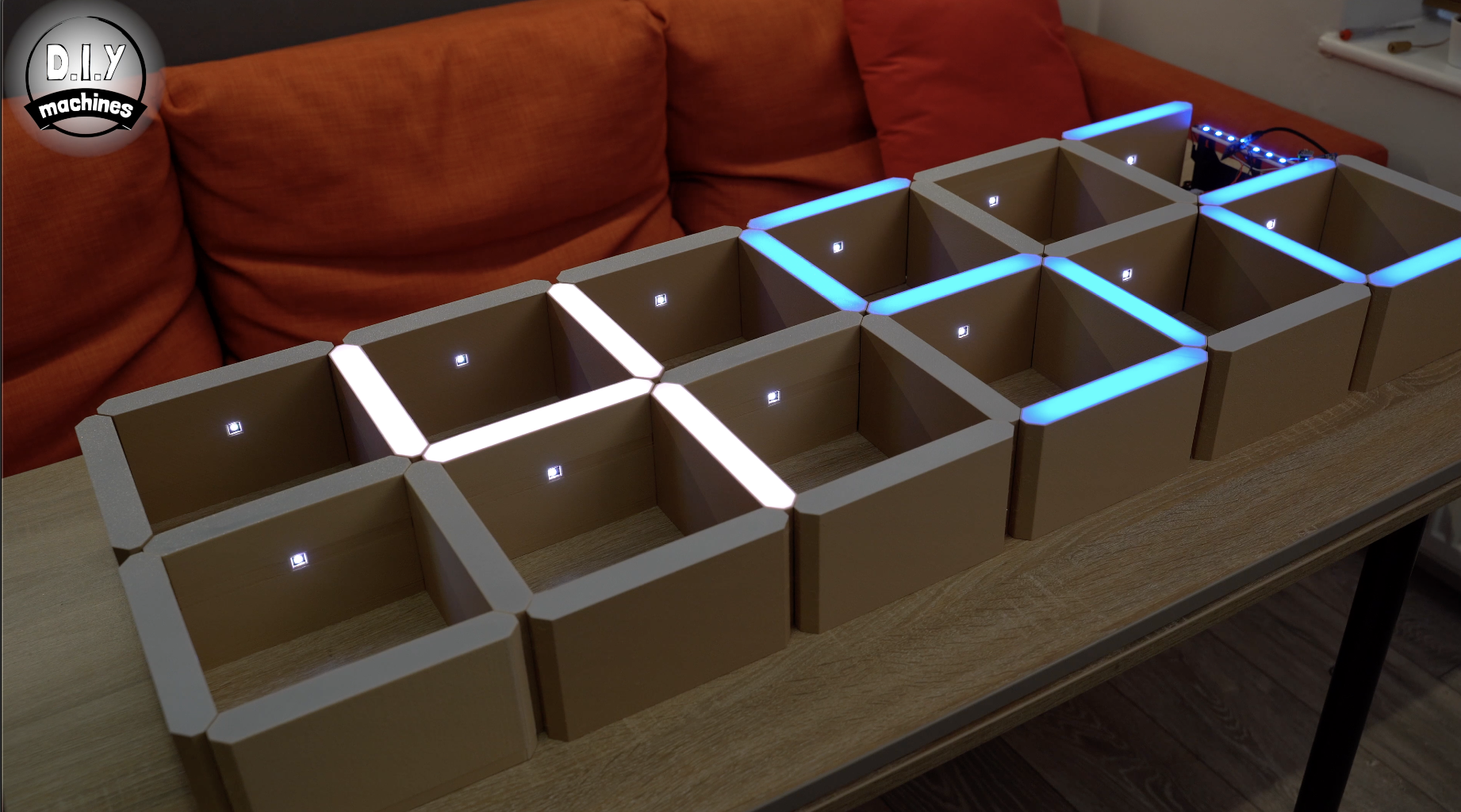
You can now replace all the shelf sleeves with the exception of the one which will cover the electronics.
Connect the USB port on the Arduino to a USB power supply and you should find that you have a fully working project!
Step 23: Connect the Mains Power Supply
Disconnect the USB cable from the Arduino.
Feed the main power supply cable through the hole in the board we made under the 3D printed support earlier. You can then connect the positive lead to the positive power block strip and the ground to the ground strip.
Check that all the wires are still held firmly by tugging on them gently.
Step 24: Position the Photoresistor
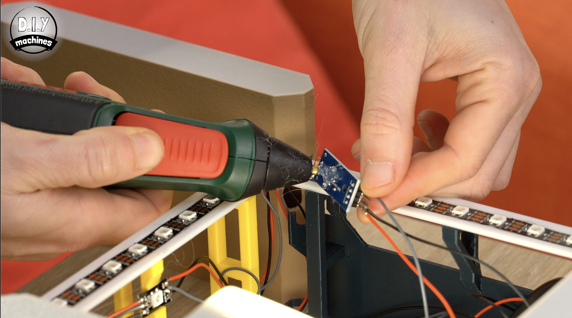
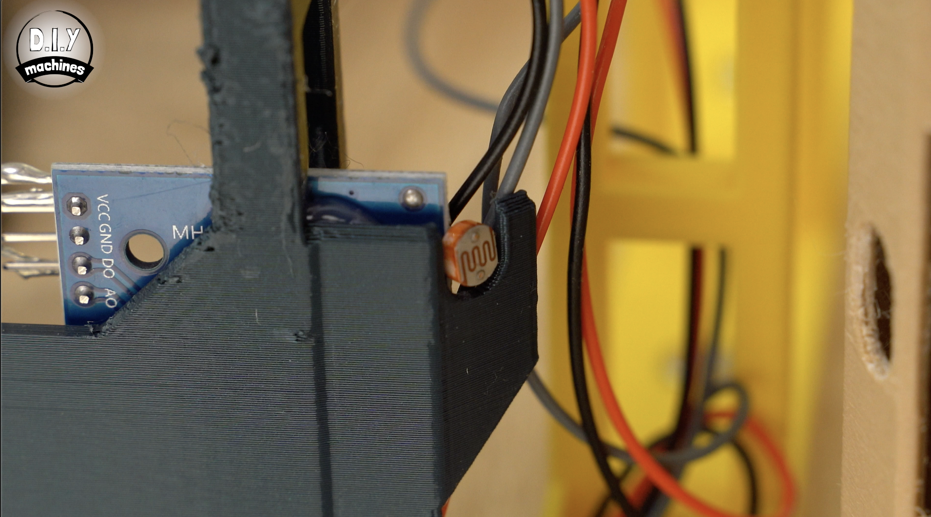
Apply some glue to the rear of the photoresistor. This is then positioned so that the circular sensor protruding from it is nestled it the U shaped cutout already made in the 3D printed support. The front of the sensor should be flush with the front so that it does not obstruct the sleeve when lowered over this support.
Step 25: Tidy the Electronics
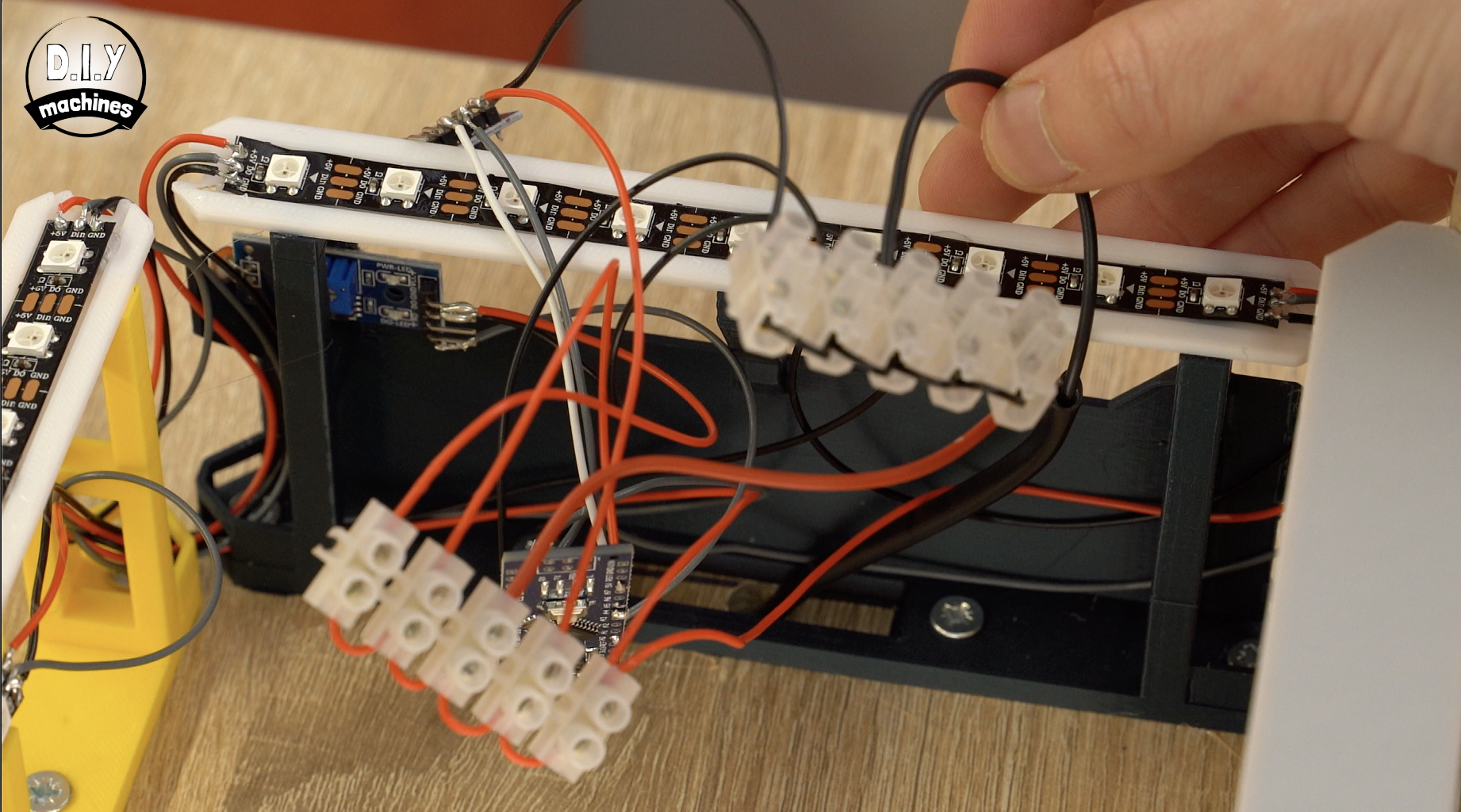
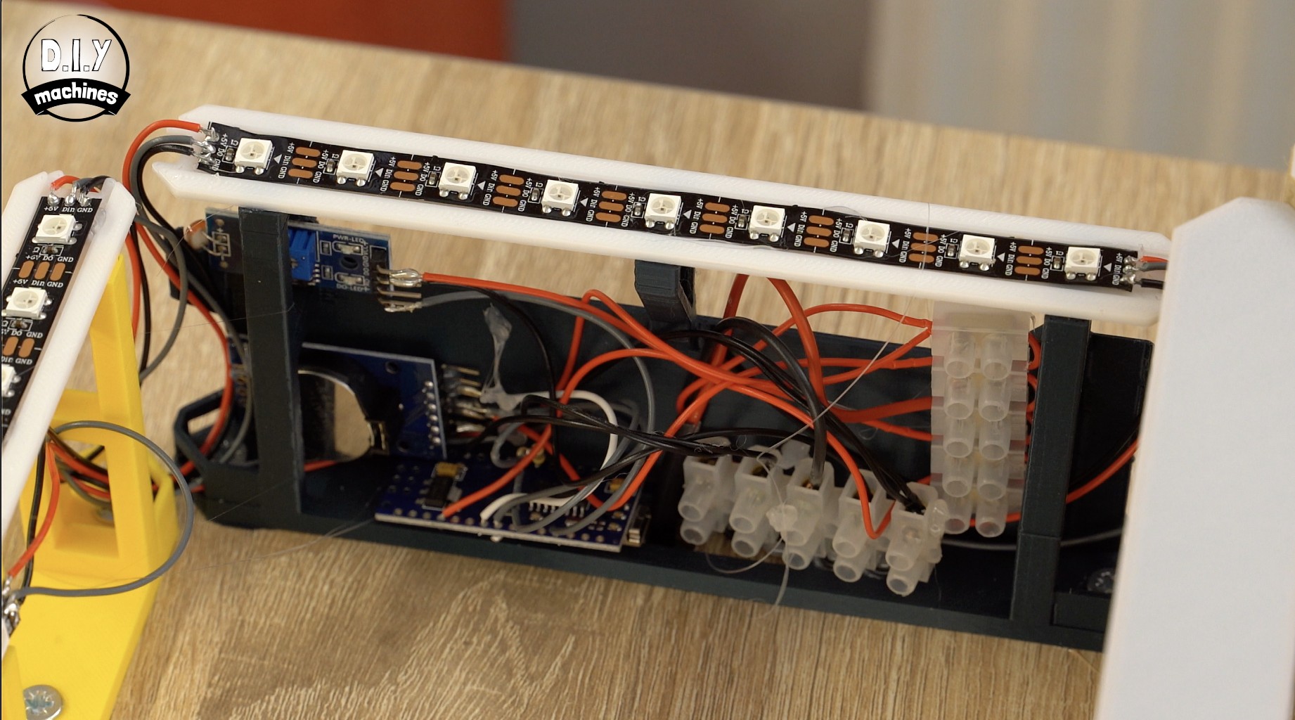
At this point, we can look to tidy up the electronics so that it can all fit neatly inside of this shelf.
I used glue to hold down the various parts inside the shelf using the large backboard of the 3D printed part to attach them to. You can fit them in any arrangement that works for you, but be careful not to put too much strain on the wires.
The photos above show before and after I arranged mine. Once done, you can slide the sleeve over the support.
Step 26: Completing the Power Supply and Mounting.
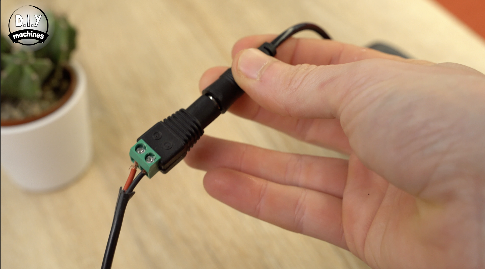
The other end of the power supply cable can be fitted onto the screw terminals. Pay attention to which is the positive and negative side of the screw terminals as it may defer to mine.
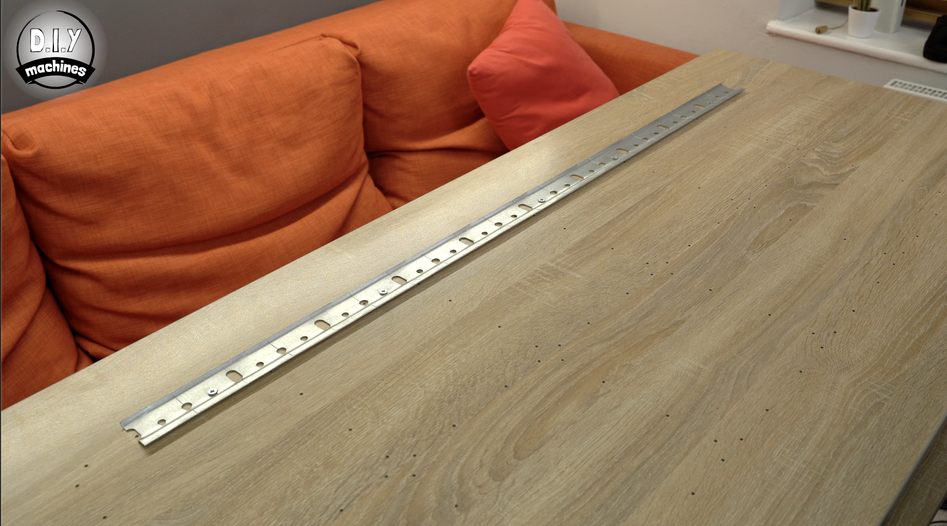
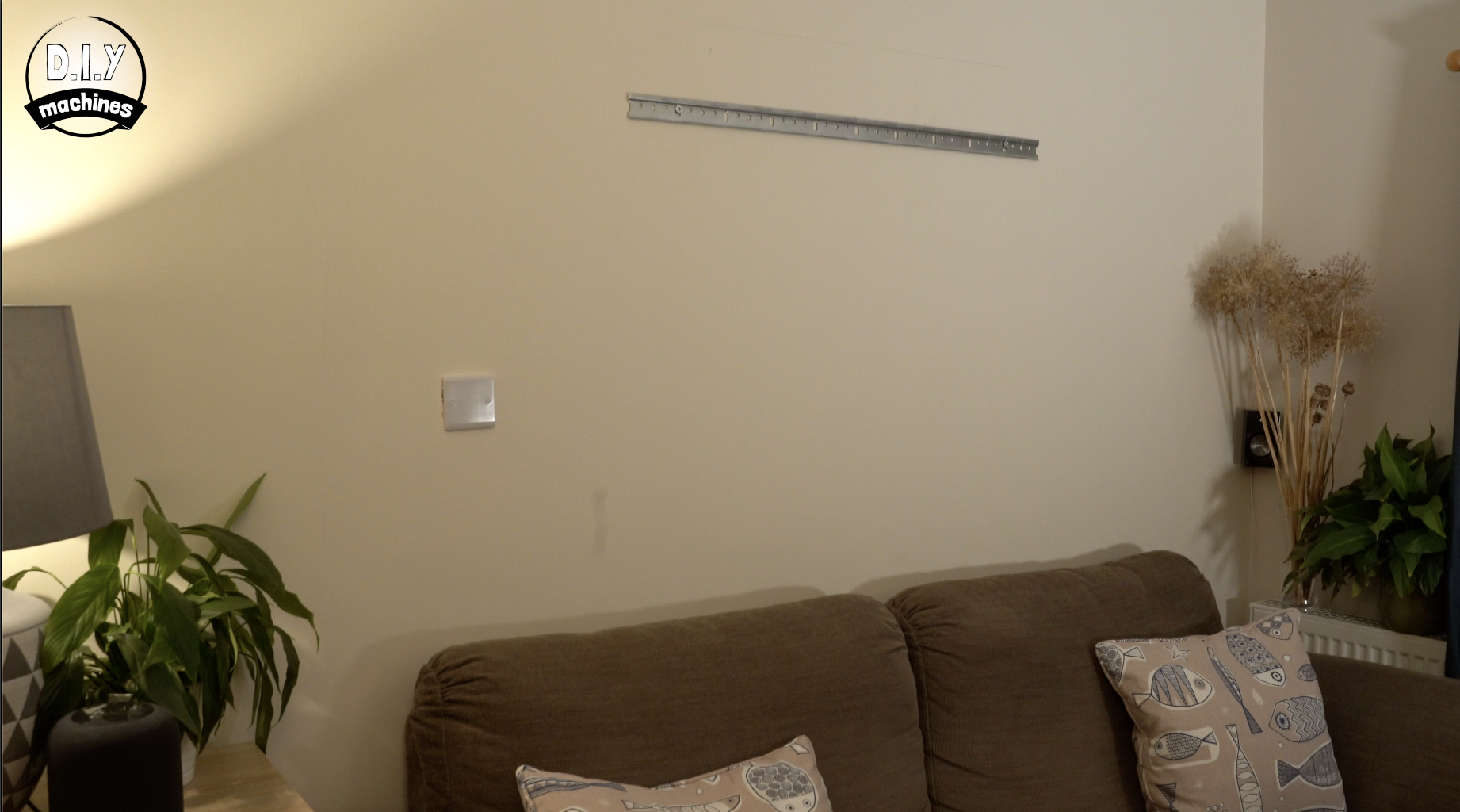
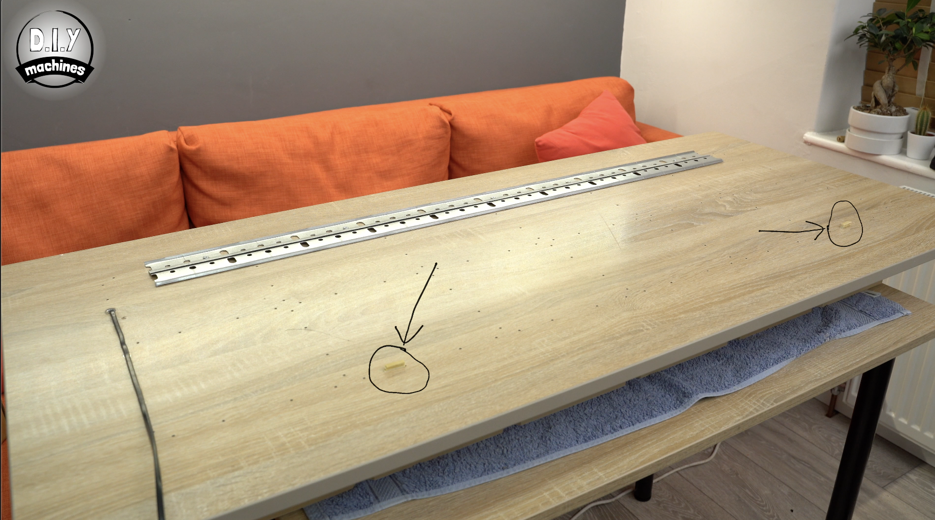
To mount my shelf edge clock onto the wall I used some kitchen wall unit brackets. One half is fitted to the clock backboard and the other half to wall. The two just slide together.
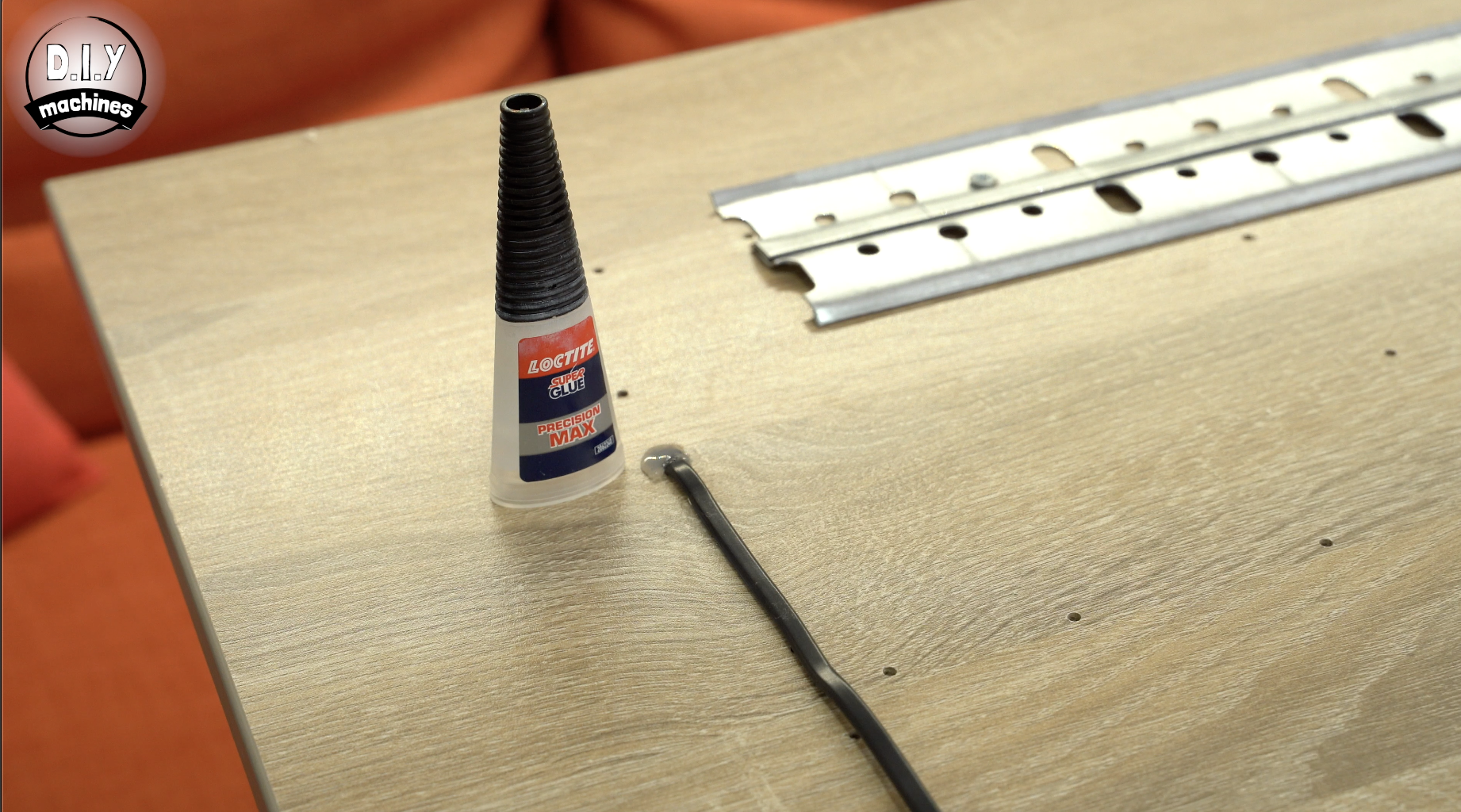
I also used some strong glue to help keep the power cable coming out of the back of the board in place and to prevent its own weight from straining the cables where they are connected to the strips of terminal blocks.
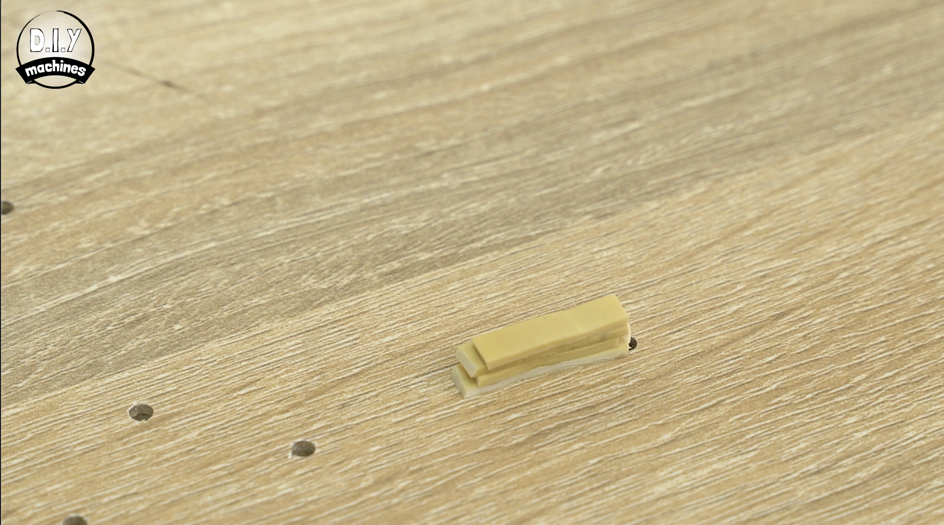
The last thing I added before putting the shelving up on the wall was two small stacks of rubber band pieces I had glued together. This acts as a small buffer which helps to prevent the bottom of the shelf marking the wall whilst also keeping it equally 'stood off' from the wall.
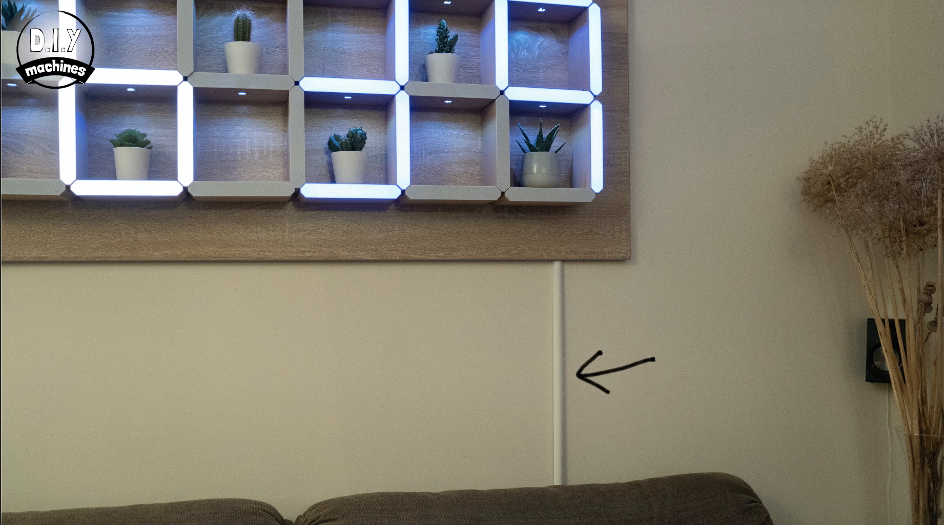
A small length of cable tidy plastic was used to help hide the otherwise black power cable. This can then be painted to match the wall colour.
Step 27: Project Complete!
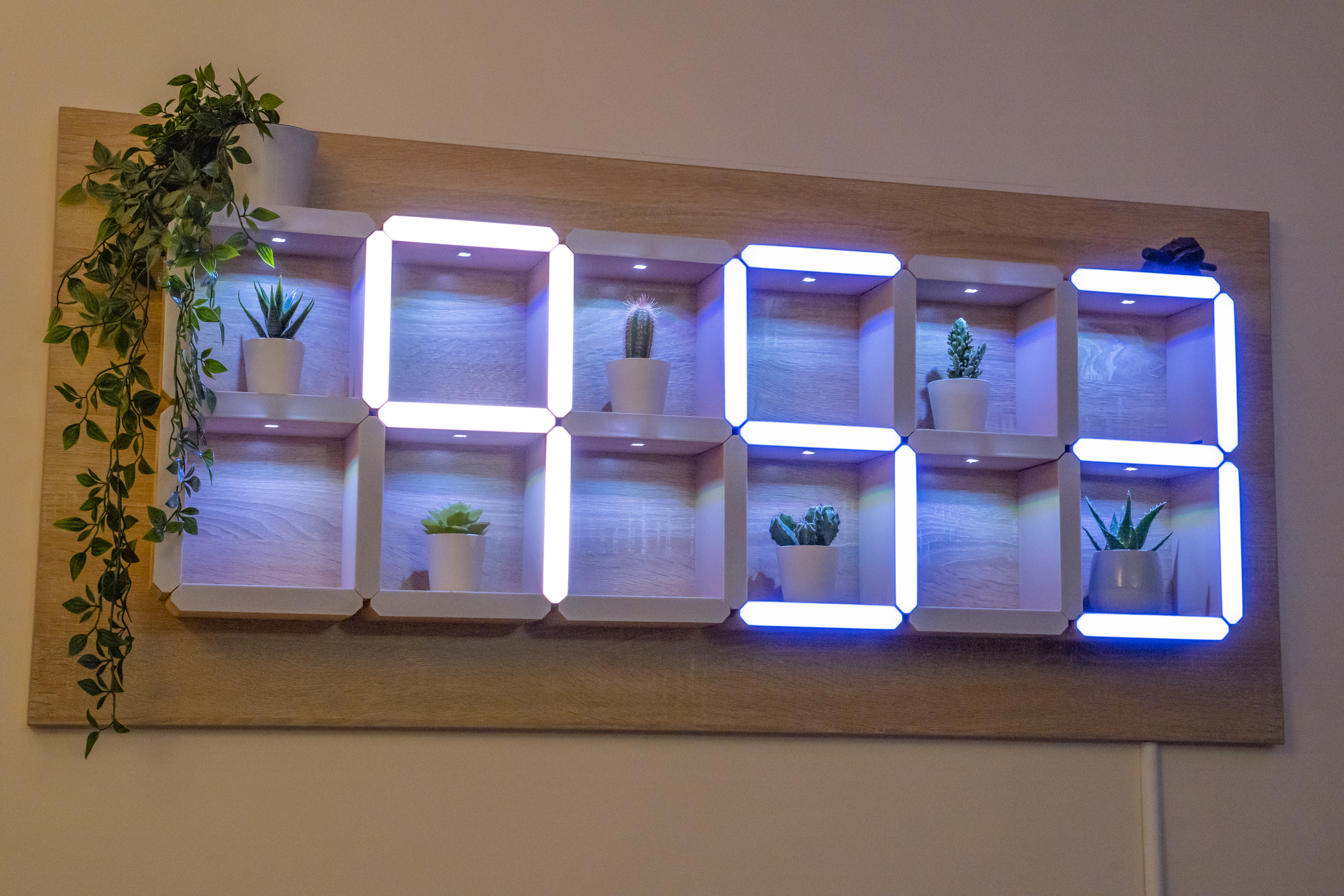
Nice, time to make a cup of tea and admire your handy work. :)
I hope you enjoyed making your own. Don't forget to take a look at some of my other projects.
Subscribe here on Electromaker and YouTube to find out what my next project is. Please feel free to share this project with anyone you know who might like to build one of their own and if you make one I'd love to see a photo of it.
Otherwise until next time chow for now!
Subscribe to my Youtube channel: https://www.youtube.com/channel/UC3jc4X-kEq-dEDYh...
Support me on Patreon: https://www.patreon.com/diymachines
Facebook: https://www.facebook.com/diymachines/
Lewis
Schematics, diagrams and documents
CAD, enclosures and custom parts
Code
Credits
Related products


Leave your feedback...