
Guitar Shaped Audio Pcb Amplifier

Made by mr-x / 3D Printing / Art / Kids & Family / Photos & Video / Robotics
About the project
I decided to build one and I wanted my amplifier to be much more unique than the existing models. So I made a guitar-shaped amplifier PCB.
Project info
Difficulty: Moderate
Platforms: Adafruit, Google, Analog Devices, JLCPCB, KiCad
Estimated time: 2 hours
License: Creative Commons Attribution CC BY version 4.0 or later (CC BY 4+)
Items used in this project
Hardware components

Software apps and online services
Story
Hey, there
We need an audio amplifier to listen to our favourite music. And lots of amplifier modules and boards are available on the market for cheap. buying one of them is not sounds good for electronics enthusiast like us. Amplifiers are working based on a very simple principle and we can build a simple one without investing much more time. So I decided to build one and I wanted my amplifier to be much more unique than the existing models. So I made a guitar-shaped amplifier PCB. So let's see how to make one. Let's get started.
LM 386 AMPLIFIER IC

first, I selected the amplifier ic from a lot of available ones. I selected the LM386 IC. I choose this ic because of its energy efficiency.
LM386 Audio amplifier features and specifications
- Supply Voltage: 4-15V
- Quiescent Power: 24mW @ 6V
- Analog input voltage 0.4V (maximum)
- Voltage Gain: 20 to 200 (26dB to 46dB)
- Speaker impedance:4Ω
- Available in 8-Pin PDIP, SOIC and VSSOP packages
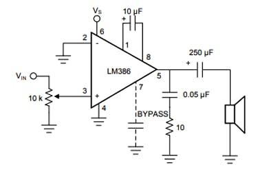
I got the basic operational circuit diagram from the internet after understanding the working of the ic made the circuit on breadboard Since the audio quality and gain depend on the component's value, I experimented with some more components and find suitable values and finalized the circuit.
The IC is powered using pin 6 (typically 5 or 9V) and the ground pin 4 is connected to the ground. The inverting pin (pin 2) is usually grounded and the Non-inverting pin (pin 3) is provided with the audio signal. This audio signal can be from a microphone or even from a 3.5mm jack. The 10k resistor is added in series with the audio signal to act as a volume control. You can ignore this potentiometer if you want to operate at maximum volume.
Pin 1 and pin 8 are used to set the gain of the Amplifier. If there is nothing connected between these pins then the default gain will be 26 dB, but we can connect a 10 uF capacitor across it to get the maximum gain of the IC which is 46dB. Pin 7 is used to connect a filtering capacitor (0.1uf) for our amplifier IC to avoid unnecessary oscillations. The amplified audio signal can be obtained from pin 5 which is connected to an 8-ohm speaker through a filtering capacitor. The RC network with 0.05uF and 10k resistor is optional.
CIRCUIT DIAGRAM OF AMPLIFIER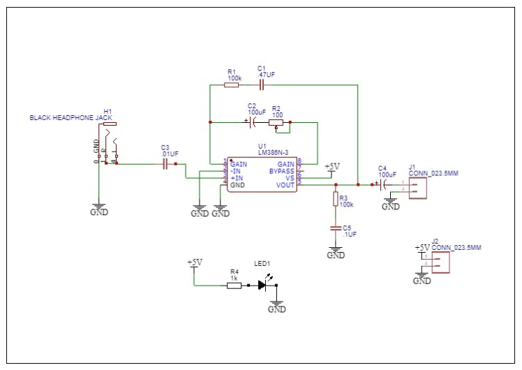
After finalising the values of the components I designed the circuit in the easyeda online platform.
COMPONENTS NEEDED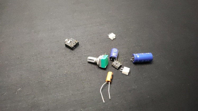
- LM386 amplifier IC-1
- 4.7k variable resistor-1
- 2 pin JST connectors-2
- 3.5mm female audio jack-1
- 0805 led -1
- 0805 resistor 100k -2
- 0805 resistor 1k -1
- 0805 capacitor.1uf-1
- 0805 capacitor.01uf -1
- 0805 capacitor.47uf -1
- electrolytic capacitor 100uf -2
- small 3w speaker-1
- 3.7-7.4v battery -1
you can also build the same amplifier using THT components. that is we can also build this amplifier without using the PCBs
PCB DESIGNING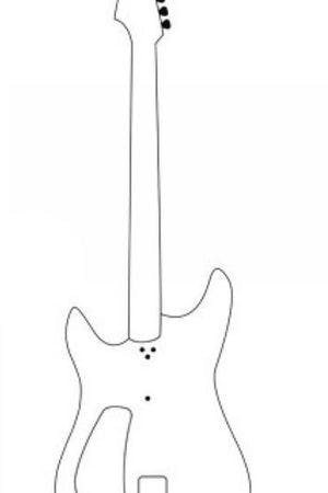
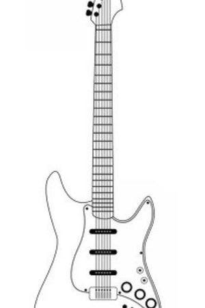
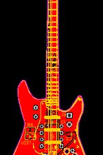
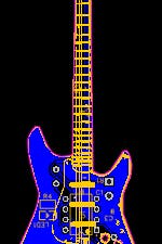
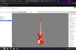
After designing the circuit I converted the circuit into PCB. to make the PCB into a guitar shape I used the insert image option of easyeda and I added the guitar image to PCB. Next, I placed all components inside the guitar image. Then I selected the board outline and drew lines over the guitar image. Then I dragged the lines and made the exact shape. I took some time to do this after completing the drawing that looks like this. Now I generated and downloaded the Gerber files for PCB fabrication.
PCB FABRICATION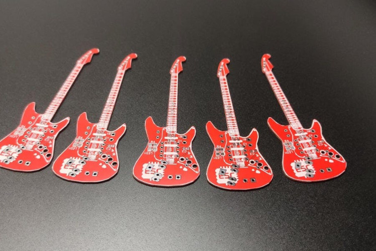
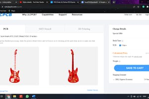

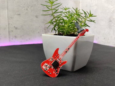
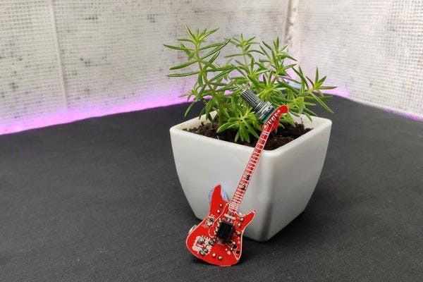
for PCB fabrication I went to Jlcpcb.com. jlcpcb gives 5 PCBs for just 2 dollars and PCB assembly starts from 0 dollars. To order click order now then add your Gerber file. After uploading you can select the board colour, quantity and thickness. Then select the shipping method and place the order. After 2 weeks I received the PCBs. You can see the cute guitar-shaped red PCBs everything seems nice and the quality is perfect.
SOLDERING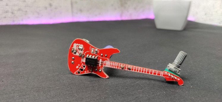
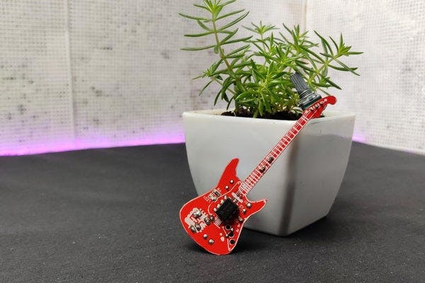
Now let's solder the SMD components here. I am soldering with my normal soldering iron. After finishing the soldering of SMD components I started the soldering of Through-hole components. I started with the lm386 ic. This is just placing the components on their right hole and soldering. After finishing the soldering job our PCB looks like this.
TESTING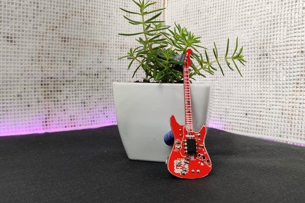
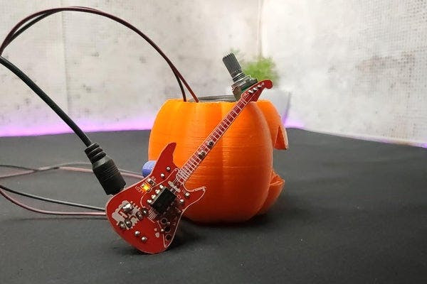
NoW let's do the test for that I connected a 3w speaker, a battery and finally the AUX cable. you can watch this working video. So this amplifier is enough to hear the music clearly. If you like this. you can try this at your home.
Schematics, diagrams and documents
Credits
Related products


Leave your feedback...