
Green Box: Remotely Controllable Power Consumption

Made by daniel-legut / 3D Printing / Home Automation / Productivity / Sustainability / IoT
About the project
Green Box: Manage & monitor your energy use remotely! Plug in, access, and save power. Eco-friendly control at your fingertips.
Project info
Difficulty: Expert
Platforms: Arduino, Python, KiCad, Blues Wireless
Estimated time: 1 month
License: Apache License 2.0 (Apache-2.0)
Items used in this project
Hardware components

View all
Software apps and online services
View all
Story
In a world where customers and investors increasingly support environmentally friendly products and services, distinguishing a genuine eco-conscious company from greenwashers is challenging. Many organizations strive to be recognized for their minimal environmental impact, with some genuinely caring for the environment. The Green Box concept caters to these environmentally conscious companies. It's crucial to acknowledge that people often forget to turn off devices, leading to unnecessary energy consumption. Most companies depend on well-trained employees to remember to switch off equipment, a method that lacks sustainability and transparency.
Personally, I often joke that I'm a one-man ecological disaster due to my environmentally harmful habits, such as not recycling and using disposable plates and cups excessively. Despite this, I consider myself environmentally aware. My individual environmental footprint may be small, but my professional decisions can significantly impact the environment. To compensate for my subpar personal environmental practices, I propose an idea to help companies reduce power consumption. This involves remotely monitoring and deactivating outlets that consume power unnecessarily, a step towards more responsible energy use in the workplace.
Getting StartedFor me, it's really frustrating when hardware moves around and isn't secure. It makes troubleshooting much more difficult if electronics are moving and aren't mounted firmly in place. So we're going to start by 3D printing the edges and laser cutting the panels. Open whatever compatible slicer software you have and prepare the.stl file for 3D printing. Please know that the image below is representative and isn't ultimately the print file I ended up using.
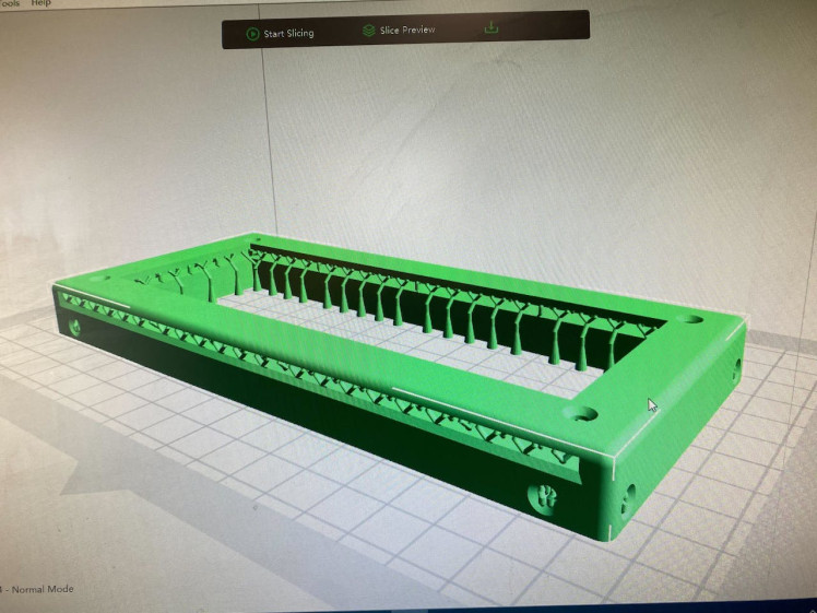
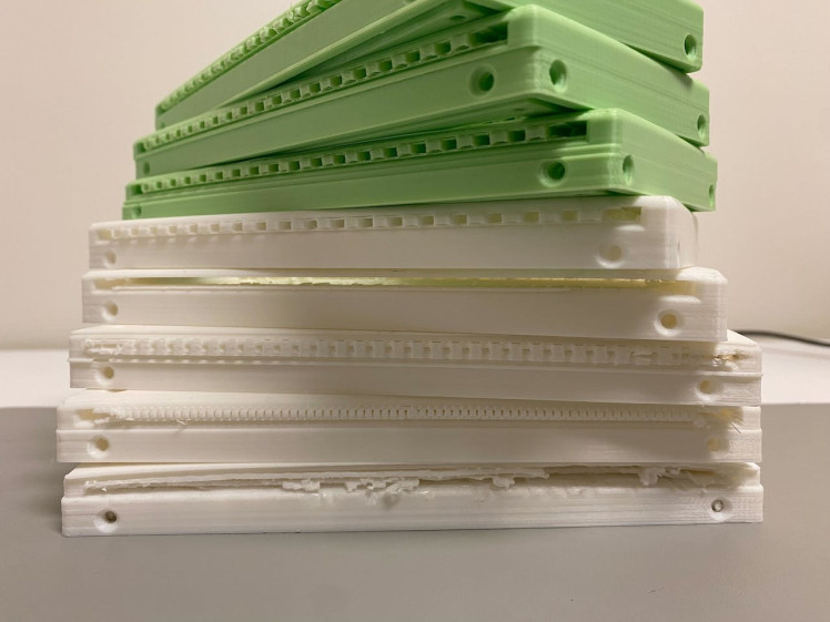
Here you can find the 3D Print gcode I used, but results may vary because you may have a different printer than the one I used. However, looking at the supports I used may be very useful. It took quite a lot of trial and error to get the supports right, and you want to avoid any layer shifts to have panels fit easily together. You'll want to print 2 of these edges.
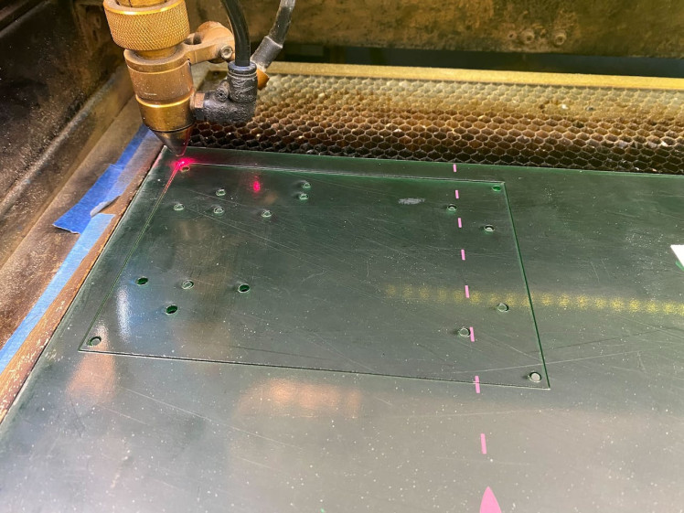
Next you want to use the .dxf files and load them into your laser cutting software and verify correct units within the software. Then utilize 70% power and 5.5mm/s jogging speed to cut the acrylic panels. Depending on how much wear and the wattage of the laser you use, you may have to use different settings to cut through the acrylic sheets. Cut out the bottom, 2 sides, top, front, and back panel. Given the tedious nature of 3D printing, it is really nice to be able to laser cut parts for any design changes. This is especially true for prototyping. There is time saved on small changes where you don't have to wait as long for a machine to run to make you a part. Less can go wrong with a laser cutting process than a 3D printing process.
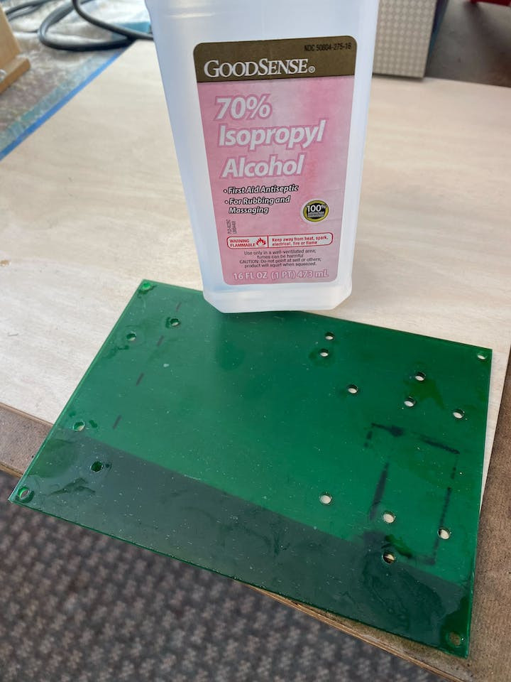
Next you'll notice there are burn marks left over from the laser cutting through.
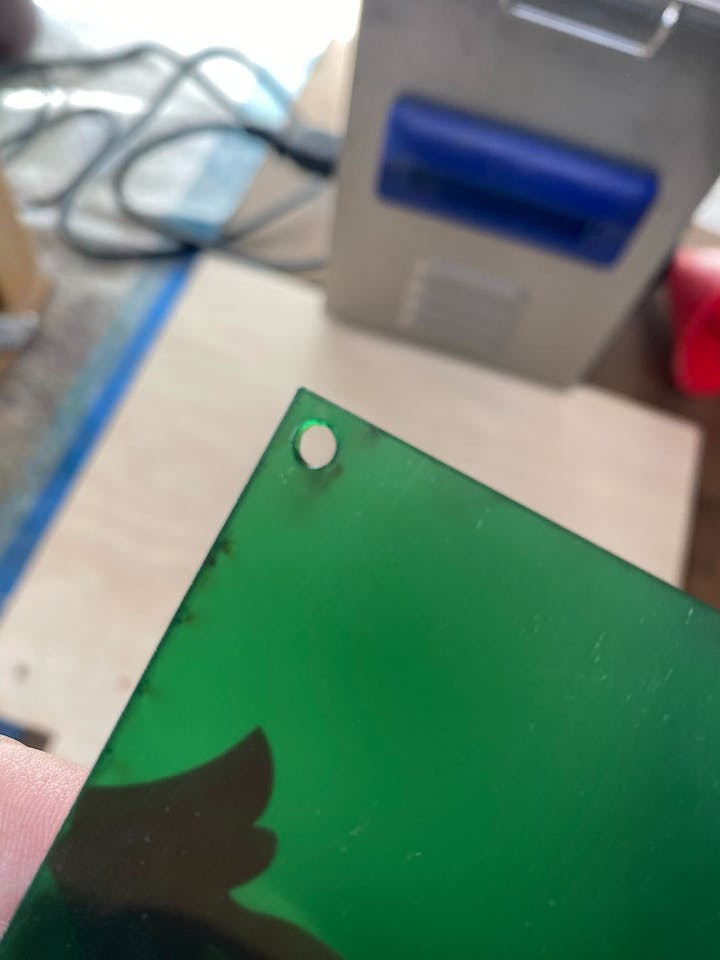
You'll want to use rubbing alcohol, cotton balls, and cotton swabs to clean that up.
That's much better!

Also, you'll want to spend time using an X-ACTO knife and other sharp tools, like from a clay sculpting kit to clean off any supports from your 3D prints.

The edge should be able to cleanly fit one of the front or back panels, and use them to gauge how cleaned up the edge parts are for the box.
Test Fit Panels and EdgesNext you'll want to test fit parts together to make sure they all go together nicely.
Back Panel

Back Panel
Front Panel

Front Panel
Now you will want to verify that the front plug fits correctly.
Try plugging something in and out of the socket, does it feel like it will hold up?

Try plugging something in and out of the socket, does it feel like it will hold up?
You will want to trim the tabs on the fused power socket to make sure they fit and snap into place on the back panel.
The tabs have to be trimmed on the socket part to fit the thickness of the acrylic sheet. There are 4 tabs that need to be trimmed.

The tabs have to be trimmed on the socket part to fit the thickness of the acrylic sheet. There are 4 tabs that need to be trimmed.
Now you'll want to make sure panels fit together snuggly like the bottom, sides, and top slide easily together and apart.
Now mount the blues wireless board by using M3 standoffs and M3 fasteners together onto the bottom panel. One of the benefits, that isn’t immediately obvious, is that this board has a dedicated data service that comes with it. This is really useful when you realize how many customer calls this can avoid troubleshooting connectivity problems. A surprisingly good number of IT departments are weary of the IoT devices that get setup within the workplace. If we are to hope for any widespread adoption of such a concept, it’s best for it to be on a separate network to make it easy for IT departments to approve it for use.
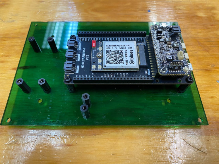
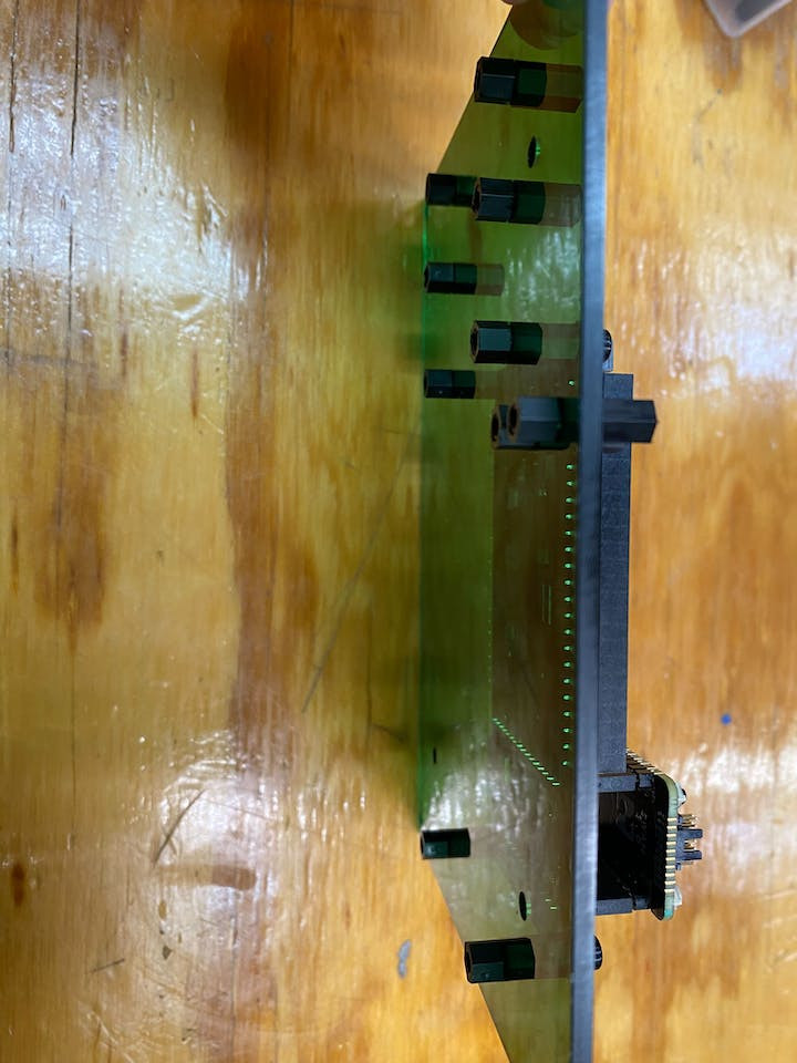
Mount the relay, ACS712 current sensor, and the AC to DC power supply.
Ignore the peculiar looking relay. I make no mistakes. This build is flawless.

Ignore the peculiar looking relay. I make no mistakes. This build is flawless.
At this point I decided to permanently glue the bottom panel to each edge using super glue, but that is a somewhat irreversible decision. You can also choose to temporarily fasten the bottom panel together. I just kept sliding panels in and out of place by flexing the bottom panel slightly. However, this might not work for everyone because if you use too much force you can crack the bottom panel. So I recommend most people use fasteners.
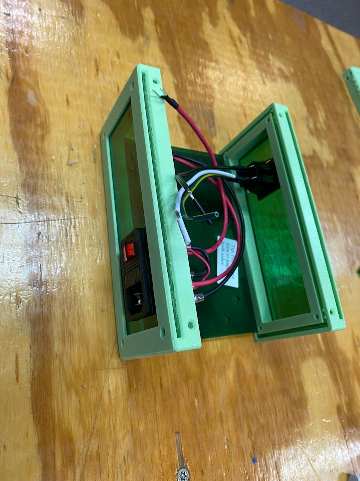
This clam shell design of the case is immensely useful for easily soldering and being able to reach your hands into the case from the sides.
This box is forgiving for design mistakes, the build process, and that's why I made it this way.

This box is forgiving for design mistakes, the build process, and that's why I made it this way.
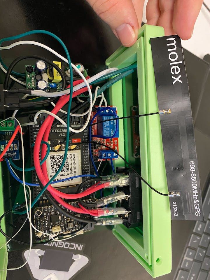
Wire Electronics TogetherSolder the electronics together according to the schematic, starting with the internal components that are mounted and working your way outward to the plug and socket on the front and back panel.
A messy workbench is one that's actually getting used.

A messy workbench is one that's actually getting used.
It would probably be best to download the KiCAD schematic and be able to zoom in and out on the wiring. In hindsight, I'd recommend de-soldering the headers on the blues wireless board for a more secure connection. I had to resort to using jumper wires and wire-wrapping some of the ends to make some of the connections.
https://github.com/legut2/Green-Box-Remotely-Controlled-Outlet/blob/main/images/schematic.png

https://github.com/legut2/Green-Box-Remotely-Controlled-Outlet/blob/main/images/schematic.png
You'll also want to carefully add the antenna once you're certain of the wiring.
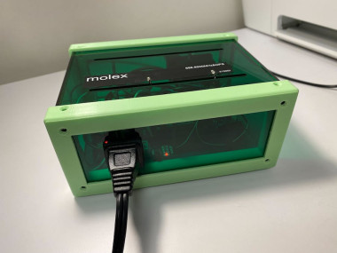
At the end, you'll want to pop out the socket in the back panel and plug in the USB cord like below to be able to flash software.
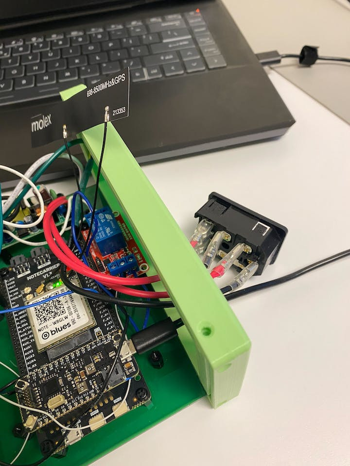
Now we're ready to move onto the software!
Programming the Green Box with Arduino IDECopy or
git clone https://github.com/legut2/Green-Box-Remotely-Controlled-Outlet.gitthe code folder into your Arduino folder, and also open the same folder up with VS Code. The path for me at the end is:
C:UsersdanielOneDriveDocumentsArduinoGreen-Box-Remotely-Controlled-Outlet-mainWe'll be using the Arduino IDE and you will want to reference the following guide to setup your Arduino IDE. I mostly did all the same setup but used the
'Blues Wireless boards'
board after importing the board manager file:
https://github.com/stm32duino/BoardManagerFiles/raw/main/package_stmicroelectronics_index.json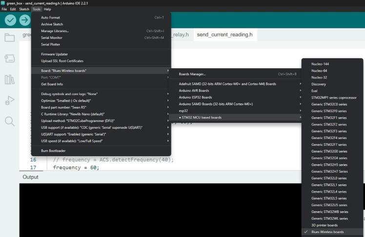
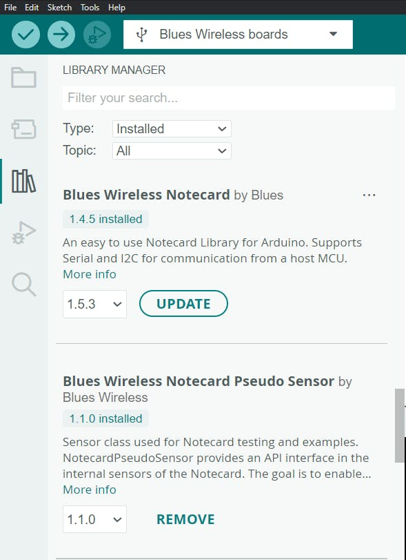
Install the following libraries from the library manager within Arduino: Blues Wireless Notecard by Blues,Blues Wireless Notecard Pseudo Sensor by Blues Wireless, and ACS712 by Rob Tillaart, and Pete Thompson

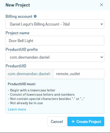
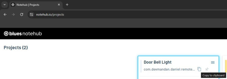
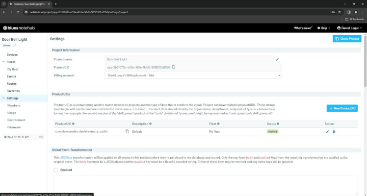
Create a notehub.io account, create a project, and copy the product UID:
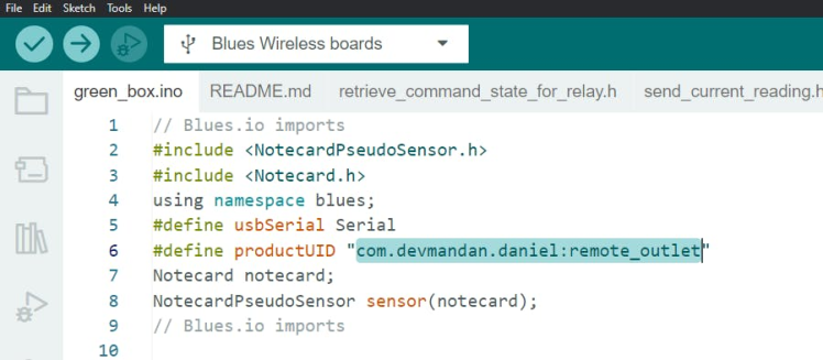
Replace the existing productUID at the top of green_box.ino:
Whenever flashing the board, it's important to keep in mind that you'll have to do the following sequence after hitting upload each time:
Press and hold the BOOT button on the Swan, press and release RESET, then release BOOT to cause the Swan to jump into its bootloader. This sequence must be done every time you want to upload firmware to the Swan.
Now go ahead and flash the board! Now measurements of current are being sent to notehub.io!
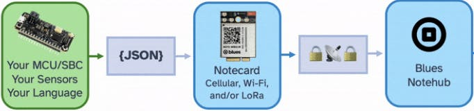
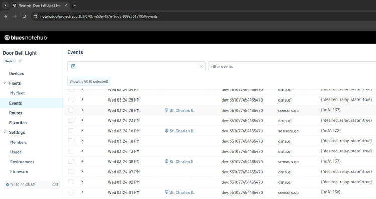
You should be able to see data recorded under events within your notehub.io dashboard now. This will allow you to send current sensor readings to be recorded.
Visual Studio Code: Using a Python Client to Turn the Outlet Off/On!Time to send the box commands and remotely control the outlet through a python client that naively sends the desired relay state over and over again.
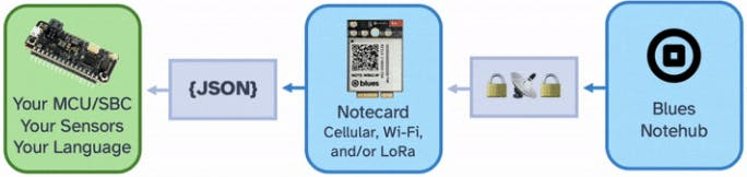
Make sure to have python 3.10 installed. Now open up VS Code and we'll go ahead and update the.env file with the appropriate credentials so we can send commands through notehub.io. You can find the .env_example file within the send_command folder. The python script send_command.py automatically sources/loads a .env. However, you need to change the .env_example file to be named .env. As best practice, it's wise not to commit this file to github or any kind of version control software.
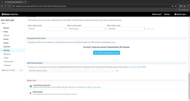
Create 'CLIENT_ID' and 'CLIENT_SECRET' within notehub.io
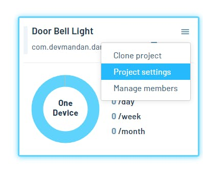
Navigate to your dashboard and click on settings.
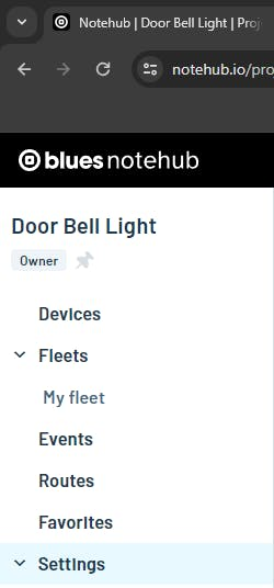
Now go ahead and scroll down through your and click on Generate programmatic access, copy the credentials into.env, and click save within the settings!
Find `PROJECT_ID` and `DEVICE_ID`
Scroll all the way back up and copy over the Project UID without the app: over to your .env file for PROJECT_ID. You can also see this as part of the URL within your web browser's address bar.
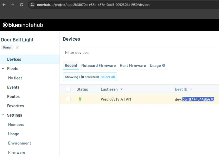
Lastly, click onto Devices and copy over the relevant ID under the Best ID column for DEVICE_ID within the .env file.
Run send_command.py
Create a virtual environment for your dependencies:
python -m venv .venvTo activate:
Windows
..venvScriptsactivateLinux/Mac
source .venv/bin/activateInstall dependencies:
pip install -r requirements.txtRun the client:
python send_command.pyType True or False and wait 20-30 seconds and the Green Box should update to that state. You can troubleshoot by looking at the events tab within notehub.io and looking at the serial monitor to see if it is looping through the notes. False should open the relay, and True should make the relay closed.
Schematics, diagrams and documents
CAD, enclosures and custom parts
Code
Credits
Related products


Leave your feedback...