





Fpga-based Automatic Smart Irrigation System

About the project
A low-cost FPGA-based automatic irrigation system using the JXCT 7-in-1 Soil Sensor to monitor seven soil parameters via Modbus RS485 and make real-time intelligent pump control decisions. The system uses a Xilinx XC7A35T Artix-7 FPGA programmed in Verilog HDL.
Project info
Difficulty: Difficult
Platforms: Autodesk, Xilinx, KiCad
Estimated time: 6 weeks
License: GNU General Public License, version 3 or later (GPL3+)
Items used in this project
Hardware components

View all
Software apps and online services

Story
The Problem Statement
Traditional irrigation systems rely only on moisture sensors, ignoring soil salinity, pH, temperature, and nutrient levels, which can cause crop damage and waste 40-60% of water. This binary logic is agronomically dangerous. For example, if the soil's Electrical Conductivity (EC) is above 2000 µS/cm, the soil is highly saline. Irrigating saline soil further concentrates salts, causing irreversible damage to plant roots and long-term soil degradation. Similarly, irrigating crops when the soil temperature is above 45°C causes immediate physiological damage due to thermal shock.
Single-parameter microcontroller systems fail to account for the complex, multi-dimensional nature of soil health, and evaluating multiple parameters sequentially introduces latency.
How It Works: The Hardware Architecture
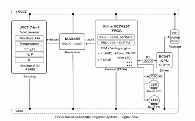
This system resolves these limitations using a deterministic, hardware-level approach. The project develops a low-cost FPGA-based automatic irrigation system using the JXCT 7-in-1 Soil Sensor (Modbus RS485, 5V) to monitor all seven soil parameters. The architecture is divided into four main functional layers:
Sensing Layer: The JXCT 7-in-1 sensor measures Moisture, Temperature, EC, pH, Nitrogen, Phosphorus, and Potassium simultaneously.
Communication Layer: An RS485 transceiver module (MAX485) converts the differential RS485 electrical signal into a standard UART-compatible TTL serial signal that the FPGA can receive.
Processing Layer: The Xilinx XC7A35T Artix-7 FPGA acts as the controller. It runs a 4-state Mealy-type Finite State Machine (IDLE, READ_SENSOR, PROCESS, OUTPUT) to evaluate thresholds. All seven parameters are evaluated against pre-programmed threshold constants simultaneously in a single clock cycle.
Output Layer: The FPGA's output pin can only supply a maximum of 3.3V at approximately 8mA, which is insufficient to drive a DC motor directly. Therefore, the system uses an NPN transistor (BC547) acting as a low-side switch between the FPGA output and the pump's negative terminal. The pump is activated ONLY when the soil is dry and all safety conditions are met.
Custom Interactive Web Simulator
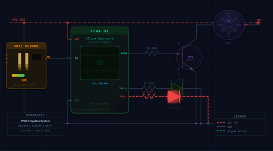
Because this project requires specific industrial sensors and FPGA hardware, our team developed a custom web-based FPGA simulator using HTML5, CSS3, and JavaScript. This simulator is designed to demonstrate the FPGA-based irrigation system in a visually interactive manner. It features an interactive circuit schematic, real-time waveform display, and sensor configuration controls.
You can interact with the live simulator here: grp9-fpgasim.netlify.app
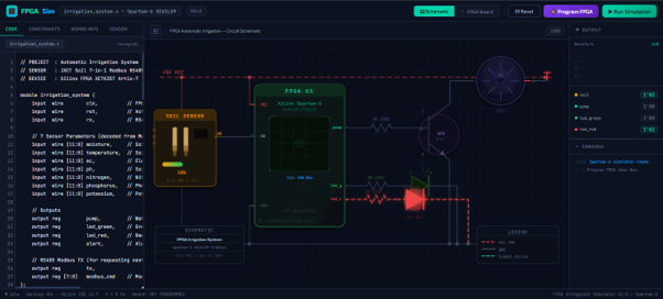
FPGA Simulation & Verification
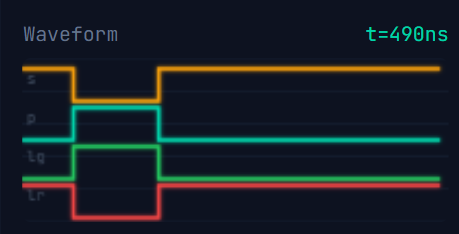
Before deploying to hardware, a synthesizable Verilog HDL irrigation system was verified using test cases covering safe irrigation, unsafe conditions, and nutrient deficiency alerts. The simulation was run using EDA Playground and Icarus Verilog. The VCD waveform file clearly showed the pump signal responding correctly to multi-parameter soil conditions.
Build Notes & Troubleshooting
Preventing Latch Inference: During Vivado synthesis analysis, warnings about inferred latches can occur if the combinational
always @(*)block does not include a default case statement and does not assign all outputs in every branch. Ensure all conditions are covered.Signal Chattering (Hysteresis): If the sensor reading fluctuates right at the threshold boundary (e.g., exactly at 30% moisture), it causes rapid oscillation between pump ON and OFF states. We implemented hysteresis by defining separate upper (70%) and lower (30%) thresholds to resolve this.
Leave your feedback...