
Esp8266 And Wii Nunchuck: Wifi Remote Control Car Robot

Made by Ron / Home Automation / Robotics / Sensors / IoT
About the project
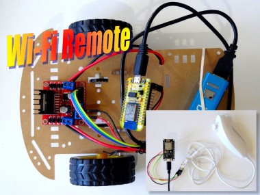
Build a robot car, and control it with Wii Nunchuck over WiFI - Quick and Easy!
Items used in this project
Hardware components

Software apps and online services
Story
Smart Car sets when combined with L298N Motor Driver Modules, offer one of the easiest ways to make robot cars. I already made an Tutorial on how you can control Smart Car with Arduino and Joystick. It is more interesting however if we can control the Car remotely. The ESP8266 modules are great low cost stand alone controllers with built in Wi-Fi, and are well fit for remotely controlling the robot car.
In this Tutorial I will show you how easy it is to remotely control a Smart Car with a Wii Nunchuck Controller over WiFi with the help of 2 NodeMCU ESP8266 modules and Visuino.
Components
1 / 2 • Picture 1

Picture 1

Picture 2
- One Smart Car chassis with 2 DC motors, gears and wheels
- 2 NodeMCU ESP8266 boards (I used both NodeMCU 0.9, and NodeMCU 1.0 versions, but any other combination, or even stand alone ESP-12 will work)
- One L298N Dual Motor Driver Module
- One Wii Nunchuck Controller
- 2 USB Power supplies with USB Cables (I used a USB Power Bank for the car, and an USB Adapter(Picture 2) for the remote but any other combination will work)
- 4 Female-Female jumper wires
- 6 Female-Male jumper wires
1 / 4 • Picture 1

Picture 1

Picture 2

Picture 3

Picture 4
- Connect the wires from one of the motors to the OUT1 and OUT2 Motor Control pins of the L298N Motor Driver Module (Picture 1)
- Connect the wires from one of the motors to the OUT3 and OUT4 Motor Control pins of the L298N Motor Driver Module (Picture 2)
- Pictures 3 shows the connected wires to the L298N Motor Driver Module
- Picture 4 shows the other end of the wires connected to the Motors and the 0.1uF anti-sparkingcapacitors soldered to the Motors as shown in this tutorial
1 / 4 • Picture 1

Picture 1

Picture 2

Picture 3

Picture 4
- Connect Male end of a Female-Male Power wire (Red wire) to the +12V Power Pin of the L298N Motor Driver Module (Picture 1 and 2)
- Connect Male end of a Female-Male Ground wire (Black wire) to the Ground Pin of the L298N Motor Driver Module (Picture 1 and 2)
- Connect the other end of the Ground wire (Black wire) to the Ground Pin of the ESP8266 NodeMCU Module (Picture 3)
- Connect the other end of the Power wire (Red wire) to the 5V (Called "Vin" in version 1.0) Power Pin of the ESP8266 NodeMCU Module (Picture 3)
- Picture 4 shows where are the Ground, 5V(Vin) Power, and Digital 2 pins of the NodeMCU 0.9
1 / 3 • Picture 1

Picture 1

Picture 2

Picture 3
- Leave the ENA and ENB jumpers on the L298N Motor Driver Module (Picture 1)
- Connect the Female end of a Female-Male wire (Control 1) (Purple wire) to the IN1 pin of the L298N Motor Driver Module (Picture 1)
- Connect the Female end of a Female-Male wire (Control 2) (Blue wire) to the IN2 pin of the L298N Motor Driver Module (Picture 1)
- Connect the Female end of a Female-Male wire (Control 3) (Green wire) to the IN3 pin of the L298N Motor Driver Module (Picture 1)
- Connect the Female end of a Female-Male wire (Control 4) (Yellow wire) to the IN4 pin of the L298N Motor Driver Module (Picture 1)
- Connect the other end of the Control 1 wire (Purple wire) to the Digital 2 Pin of the ESP8266 NodeMCU Module (Picture 2)
- Connect the other end of the Control 2 wire (Blue wire) to the Digital 3 Pin of the ESP8266 NodeMCU Module (Picture 2)
- Connect the other end of the Control 3 wire (Green wire) to the Digital 4 Pin of the ESP8266 NodeMCU Module (Picture 2)
- Connect the other end of the Control 4 wire (Yellow wire) to the Digital 5 Pin of the ESP8266 NodeMCU Module (Picture 2)
- Picture 4 shows in Red the NodeMCU 0.9 pins that ware connected in this step. In Blue are shown the connections done in the previous step.
1 / 2 • Picture 1

Picture 1

Picture 2
Add a USB power source (In my case a rechargeable USB power bank) (Picture 1)
- Use straps, rubber bands, screws or any other convenient ways to secure the wires and boards to the chassis (Pictures 1 and 2)
1 / 6 • Picture 1

Picture 1

Picture 2

Picture 3

Picture 4

Picture 5

Picture 6
The Wii Nunchuck Controller uses I2C interface. Picture 1 shows the I2C pins of the Wii Nunchuck controller connector. The Connector is not designed to connect wires to it, but to be plunged into another specially designed connector, however there is an easy way to connect Male jumper wires into it. The connector has small openings next to the pins (Picture 2), and by inserting the pin of a male jumper wire (Picture 3), we can make a connection. There are also specially designed adapters for Wii Nunchuck Controllers, but I don't have one at the moment, so I inserted the wires directly.
- Place the connector with its long flat side down as shown on Pictures 1 and 2
- Insert the Male end of one of the Male-Female jumper wires (Red wire) into the small opening bellow the Bottom Left (3.3V Power) pin (Picture 3)
- Insert the Male end of another Male-Female jumper wire (Green wire) into the small opening bellow the Bottom Right (SDA/Data) pin (Picture 4)
- Insert the Male end of another Male-Female jumper wire (Yellow wire) into the small opening above the Top Left (SCL/Clock) pin (Picture 5)
- Insert the Male end of another Male-Female jumper wire (Black wire) into the small opening above the Top Right (GND/Ground) pin (Picture 6)
1 / 3 • Picture 1

Picture 1

Picture 2

Picture 3
- Connect the other end of the SCL wire (Yellow wire) to SCL/Digital pin 1 of the ESP8266 NodeMCU board (Picture 1)
- Connect the other end of the SDA wire (Green wire) to SDA/Digital pin 2 of the ESP8266 NodeMCU board (Picture 1)
- Connect the other end of the Ground wire (Black wire) to the Ground pin of the ESP8266 NodeMCU board (Picture 2)
- Connect the other end of the Power wire (Red wire) to the 3.3V Power pin of the ESP8266 NodeMCU board (Picture 2)
- Picture 3 shows where are the Ground, 3.3V Power, Digital 1, and Digital 2 pins of the NodeMCU 1.0
1 / 2 • Picture 1

Picture 1

Picture 2
Please be aware that there are some critical bugs in Arduino IDE 1.6.6. Make sure that you install 1.6.7 or higher, otherwise this Tutorial will not work!
- Click on the "Tools" button on the Arduino component (Picture 1) in Visuino
- When the dialog appears, select "NodeMCU ESP-12" as shown on Picture 2
1 / 5 • Picture 1

Picture 1

Picture 1
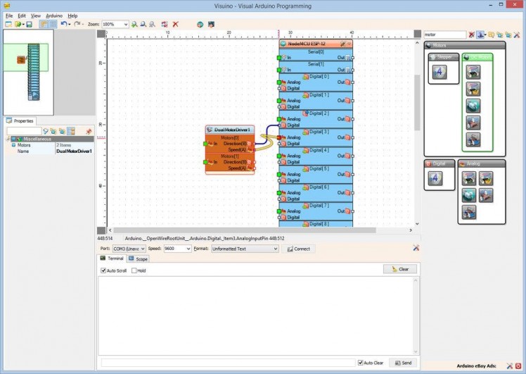

- Type "motor" in the Filter box of the Component Toolbox then select the "Dual DC Motor Driver 2 Pin Bridge (L9110S, L298N)" component (Picture 1), and drop it in the design area
- Since we left the ENA and ENB jumpers on the L298N Motor Driver module, we will control it with only 2 pins per motor. Visuino also includes a component to control it with the 3 pins, if the jumpers are disconnected, but this is not necessary
- Connect the "Direction(B)" output pin of the "Motors[ 0 ]" channel of the DualMotorDriver1 component to the "Digital" input pin of "Digital[ 2 ]" channel of the “NodeMCU ESP-12” component (Picture 1)
- Connect the "Speed(A)" output pin of the "Motors[ 0 ]" channel of the DualMotorDriver1 component to the "Analog" input pin of "Digital[ 3 ]" channel of the “NodeMCU ESP-12” component (Picture 2)
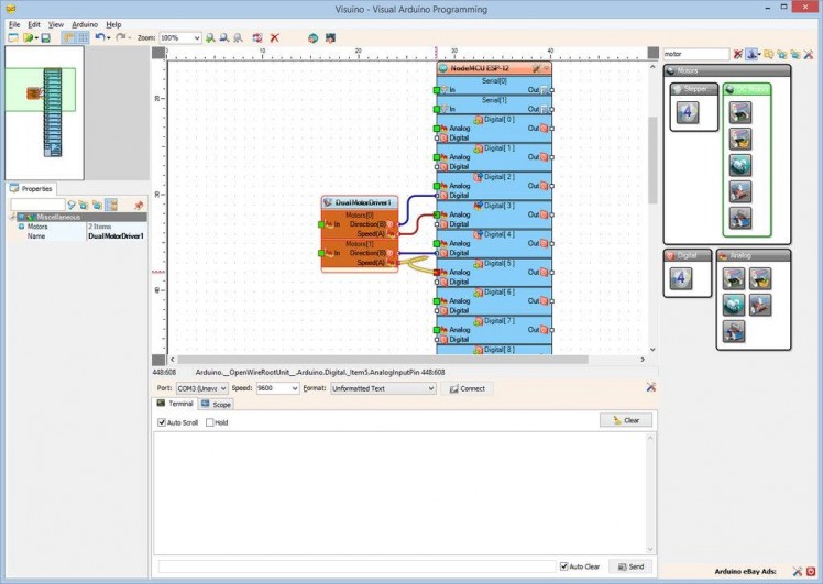
- Connect the "Direction(B)" output pin of the "Motors[ 1 ]" channel of the DualMotorDriver1 component to the "Digital" input pin of "Digital[ 4 ]" channel of the “NodeMCU ESP-12” component (Picture 3)
- Connect the "Speed(A)" output pin of the "Motors[ 1 ]" channel of the DualMotorDriver1 component to the "Analog" input pin of "Digital[ 5 ]" channel of the “NodeMCU ESP-12” component (Picture 4)
1 / 3 • Picture 1

Picture 1

Picture 2

Picture 3
- In the Object Inspector, expand the "Modules" property, then the "WiFi" sub property, then the "AccessPoint" sub property (Picture 1)
- Set the value of the "SSID" sub property of the "AccessPoint", to “SmartCar1” (Picture 1)
We will assign a fixed IP address of 200.200.200.200 so we can easily connect to the module by IP:
- In the Object Inspector, expand the "Config" sub property of the "AccessPoint" property (Picture 2)
- Set the value of the “Enabled” sub property of the Config to “True” (Picture 2)
- Set the value of the “IP” sub property to "200.200.200.200" (Picture 3)
1 / 3 • Picture 1

Picture 1

Picture 2

Picture 3
Next we need to add an UDP socket for the communication.
- In the Object Inspector, click on the "..." button next to the value of the "Sockets" sub property of the "WiFi" property (Picture 1)
- In the Sockets editor select “UDP Socket”, and then click on the "" button (Picture 2)
- In the Object Inspector set the value of the “Port” to “8888” (Picture 4)
1 / 4 • Picture 1

Picture 1

Picture 2

Picture 3

Picture 4
The Remote controller needs to send the speeds of the left and right motors. The simplest way is to send them in binary floating point form as a structure. We need to decode it properly. For this we need a “Split Structure” component with 2 “Analog” elements in it.
- Type "split" in the Filter box of the Component Toolbox then select the "Split Structure" component (Picture 1), and drop it in the design area
- Click on the "Tools" button (Picture 2) to open the Elements editor (Picture 3)
- In the "Elements" editor select the “Analog” element, and then click 2 times on the "" button (Picture 3) to add 2 Analog elements (Picture 4)
- Close the Elements editor
1 / 4 • Picture 1

Picture 1

Picture 2

Picture 3

Picture 4
- Connect the "Out" pin of the "Elements.Analog1" of the SplitStructure1 component to the "In" pin of the "Motors[ 0 ]" channel of the DualMotorDriver1 component (Picture 1)
- Connect the "Out" pin of the "Elements.Analog2" of the SplitStructure1 component to the "In" pin of the "Motors[ 1 ]" channel of the DualMotorDriver1 component (Picture 2)
- Connect the “Out” pin of the “Modules.WiFi.Sockets.UDPSocket1” of the “NodeMCU ESP-12” component, to the “In” pin of the SplitStructure1 component (Picture 3)
The Smart Car programming part of the project is completed!
On Picture 4 you can see the complete Visuino Diagram.
Generate, Compile, and Upload the ESP8266 code for the Smart Car
1 / 2 • Picture 1

Picture 1

Picture 2
- In Visuino, Press F9 or click on the button shown on Picture 1 to generate the Arduino code, and open the Arduino IDE
- Connect the first NodeMCU module (The one on the Smart Car) with USB cable to the computer
- Select the board type and serial port as I have shown you in this tutorial
- Make sure you have installed the latest staging version of the ESP support! The stable release does not have some of the latest features, and you will have errors when you try to compile!
- In the Arduino IDE, click on the Upload button, to compile and upload the code (Picture 2)
1 / 5 • Picture 1

Picture 1

Picture 2

Picture 3

Picture 4

Picture 5
Now lets program the Wii Nunchuck Remote Control module.
- Start new project.
- Click on the "Tools" button on the Arduino component, and when the dialog appears, select "NodeMCU ESP-12" as you did in Step 8 for the Smart Car module
Next we need to configure the module to connect to the Access Point of the Smart Car module, and use a fixed IP Address of 200.200.200.100 so it can be on the same 200.200.200.X subnet.
- In the Object Inspector, expand the “Modules” property, then the “WiFi” sub property, then the “AccessPoints” sub property, and click on the "..." button next to its value (Picture 1)
- In the "AccessPoins" editor, select “WiFi Access Point”, and then click on the "" button on the left, to add the access point (Picture 2)
- In the Object Inspector, set the value of the "SSID" property to “SmartCar1” (Picture 3)
- In the Object Inspector, expand the “Config” property, and set the value of the “Enabled” sub property to “True” (Picture 4)
- In the Object Inspector, set the value of the “IP” sub property to “200.200.200.100” (Picture 5)
1 / 4 • Picture 1

Picture 1

Picture 2

Picture 3

Picture 4
Next we need to add an UDP socket for the communication.
- In the Object Inspector, click on the "..." button next to the value of the "Sockets" sub property of the "WiFi" property (Picture 1)
- In the Sockets editor select “UDP Socket” on the right, and then click on the "" button on the left (Picture 2)
- In the Object Inspector, set the value “RemoteIPAddress” property to “200.200.200.200” (Picture 3) – this is the fixed IP address that we will assigned to the Smart Car ESP8266 module
- In the Object Inspector set the value of the “RemotePort” to “8888” (Picture 4)
- Close the "Sockets" dialog
1 / 3 • Picture 1

Picture 1

Picture 2
- Type "wii" in the Filter box of the Component Toolbox then select the "Wii Nunchuck Controller" component (Picture 1), and drop it in the design area
- Connect the "Out" pin of the WiiNunchuck1 component (Picture 2) to the to the "In" pin of the I2C channel of the “NodeMCU ESP-12” component (Picture 3)
1 / 4 • Picture 1

Picture 1

Picture 2

Picture 3

Picture 4
The Wii Nunchuck Joystick does not produce Picture 1a full range of values from 0.0 to 1.0. Instead the values are from around 0.14 to around 0.89 . The values may differ a bit from controller to controller. To convert the Nunchuck "Y" range into a full range we can use Map Range component. We can also correct the "X" range, but that is not necessary, as for turning a full range is not so important as for forward/reverse speed.
- Type "map" in the Filter box of the Component Toolbox then select the "Map Range" component (Picture 1), and drop it in the design area
- Connect the "Y" pin of the "Stick" group of the WiiNunchuck1 component to the "In" pin of the MapRange1 component (Picture 2)
- Select the MapRange1 component (Picture 3)
- In the Object Inspector expand the "InputRange" property (Picture 3)
- In the Object Inspector set the value of the "Max" sub-property to "0.89" (Picture 3)
- In the Object Inspector set the value of the "Min" sub-property to "0.14" (Picture 4)
1 / 3 • Picture 1

Picture 1

Picture 2

Picture 3
- Type "steer" in the Filter box of the Component Toolbox then select the "Steering Differential" component (Picture 1), and drop it in the design area.This component will calculate the speed of the left and right motors based on the Speed and Direction from the Joystick (X and Y control)
- Connect the "X" pin of the "Stick" group of the WiiNunchuck1 component to the "Direction" input pin of the Steering1 component (Picture 2)
- Connect the "Out" pin of the MapRange1 component to the "Speed" input pin of the Steering1 component (Picture 3)
1 / 4 • Picture 1

Picture 1

Picture 2

Picture 4
We need to send a packet of 2 analog values for the speeds of the 2 motors. To do this we will make a structure with 2 analog values and will send it over the UDP socket.
- Type "make" in the Filter box of the Component Toolbox then select the "Make Structure" component (Picture 1), and drop it in the design area
- Click on the "Tools" button (Picture 2) to open the "Elements" editor (Picture 3)
- In the "Elements" editor select the “Analog” element, and then click 2 times on the "" button (Picture 3) to add 2 Analog elements (Picture 4)
- Close the "Elements" editor.
1 / 3 • Picture 1

Picture 1

Picture 2

Picture 3
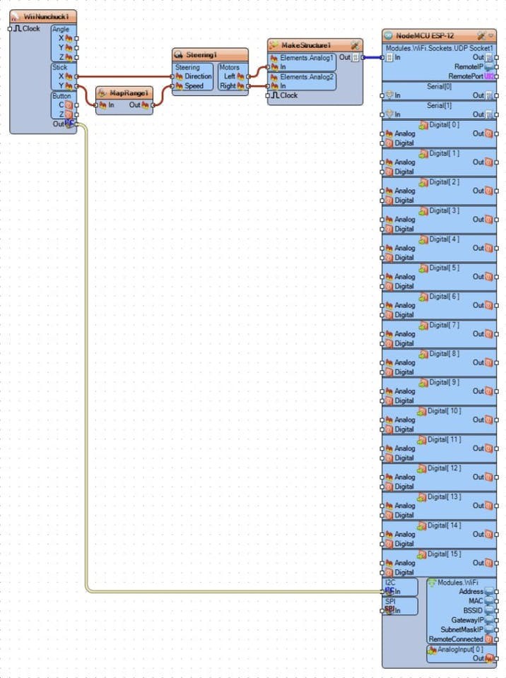
- Connect the "Left" pin of the "Motors" pin list of the Steering1 component to the "In" pin of he “Elements.Analog1” element of the MakeStructure1 component (Picture 1)
- Connect the "Right" pin of the "Motors" pin list of the Steering1 component to the "In" pin of the "Elements.Analog2" channel of the MakeStructure1 component (Picture 2)
- Connect the “Out” pin of the MakeStructure1 component to the “In” pin of the "Modules.WiFi.Sockets.UDPSocket1” of the “NodeMCU ESP-12” component (Picture 3)
1 / 2 • Picture 1

Picture 1

Picture 2
- In Visuino, Press F9 or click on the button shown on Picture 1 to generate the Arduino code, and open the Arduino IDE
- Connect the second NodeMCU module (The one with the Wii Nunchuck Controller) with USB cable to the computer
- Select the board type and serial port as I have shown you in this tutorial
- In the Arduino IDE, click on the Upload button, to compile and upload the code (Picture 2)
At this point you can already start playing with the Smart Car.
If you connect the Power to the car and the remote, you can use the Joystick of the Wii Nunchuck to control the car by moving the Joystick forward and backward the car will move in the Forward or Backward direction, and moving the Joystick left and right will make the car turn left and right.
If the car is not moving as expected, you may need to swap the wires controlling the motors connected in Step 3 to make them rotate in the proper direction.
On the Picture you can see the complete Visuino diagram.
If this is enough, you can ignore the following steps, however if you also want to be able to control the car with the tilt of the Wii Nunchuck, continue with the next step.
In Visuino: Add and connect Analog Toggle Switch component
1 / 5 • Picture 1

Picture 1

Picture 2

Picture 3

Picture 4

Picture 5
We want to use the "Z" key on the Wii Nunchuck to switch between the Joystick and the Tilt control. To switch the controls we will need to add 2 Analog switches:
- Type "switch" in the Filter box of the Component Toolbox then select the "Analog Toggle Switch" component (Picture 1), and drop two of them in the design area
- Connect the "X" pin of the "Stick" group of the WiiNunchuck1 component to the "False" input pin of the AnalogToggleSwitch1 component (Picture 2)
- Connect the "Out" pin of the AnalogToggleSwitch1 component to the "Direction" input pin of the Steering1 component (Picture 3)
- Connect the "Out" pin of the MapRange1 component to the "False" input pin of the AnalogToggleSwitch2 component (Picture 4)
- Connect the "Out" pin of the AnalogToggleSwitch2 component to the "Speed" input pin of the Steering1 component (Picture 5)
1 / 5 • Picture 1

Picture 1

Picture 2

Picture 3

Picture 4

Picture 5
The Wii Nunchuck Tilt does not produce a full range of values from 0.0 to 1.0 similar to the way the Joystick works. To convert the Nunchuck "X" and "Y" tilt ranges into full ranges we can use Map Range components.
- Type "map" in the Filter box of the Component Toolbox then select the "Map Range" component (Picture 1), and drop two of them in the design area
- Connect the "X" pin of the "Stick" group of the WiiNunchuck1 component to the "In" pin of the MapRange2 component (Picture 2)
- Connect the "Out" pin of the MapRange2 component to the "True" input pin of the AnalogToggleSwitch1 component (Picture 3)
- Connect the "Y" pin of the "Stick" group of the WiiNunchuck1 component to the "In" pin of the MapRange3 component (Picture 4)
- Connect the "Out" pin of the MapRange2 component to the "True" input pin of the AnalogToggleSwitch2 component (Picture 5)
1 / 4 • Picture 1

Picture 1

Picture 2

Picture 3

Picture 4
The mapping values in this step are based on my Nunchuck controller. You may need to use slightly different values for your controller.
- Select the MapRange1 component (Picture 1)
- In the Object Inspector expand the "InputRange" property (Picture 1)
- In the Object Inspector set the value of the "Max" sub-property to "0.6" (Picture 1)
- In the Object Inspector set the value of the "Min" sub-property to "0.3" (Picture 2)
- Select the MapRange2 component (Picture 3)
- In the Object Inspector expand the "InputRange" property (Picture 3)
- In the Object Inspector set the value of the "Max" sub-property to "0.7" (Picture 3)
- In the Object Inspector set the value of the "Min" sub-property to "0.19" (Picture 4)
1 / 6 • Picture 1

Picture 1

Picture 2

Picture 3

Picture 4

Picture 5

Picture 6
To implement the Toggle functionality, we need to use a Flip-Flop. The most convenient for this purpose is the Toggle(T)-FlipFlop.
To control the FlipFlop we need to generate event only when the button is pressed. For this we need an edge detector, to detect the change of the digital level from False to True
- Type "edge" in the Filter box of the Component Toolbox then select the "Detect Edge" component (Picture 1), and drop it in the design area
- Type "flip" in the Filter box of the Component Toolbox then select the "Toggle(T) Flip-Flop" component (Picture 2), and drop it in the design area
- Connect the "Z" pin of the "Button" group of the WiiNunchuck1 component to the "In" pin of the DetectEdge1 (Picture 3)
- Connect the "Out" pin of the DetectEdge1 to the "In" pin of the Flip-Flop(Picture 4)
- Connect the "Out" pin of the TFlipFlop1 to the "Select" input pin of the AnalogToggleSwitch2 component (Picture 5)
- Connect the "Out" pin of the TFlipFlop1 to the "Select" input pin of the AnalogToggleSwitch1 component (Picture 6)
1 / 2 • Picture 1

Picture 1

Picture 2
- In Visuino, Press F9 or click on the button shown on Picture 1 to generate the Arduino code, and open the Arduino IDE
- Connect the second NodeMCU module (The one with the Wii Nunchuck Controller) with USB cable to the computer
- In the Arduino IDE, click on the Upload button, to compile and upload the code (Picture 2)
1 / 4 • Picture 1

Picture 1

Picture 2

Picture 3

Picture 4
Congratulations! You have a full remote control over your robot.
The Video shows the connected and powered up Smart Car.
If you power up the Car and the Remote, you can use the Wii Nunchuck Joystick to control the car by moving the Joystick forward and backward the car will move in the Forward or Backward direction, and moving the Joystick left and right will make the car turn left and right.
If you press the "Z" button on the Wii Nunchuck, you will switch to controlling the car with the tilt of the controller as seen in the video.
Pressing "Z" again, switches back to Joystick control.
On the Picture you can see the complete Visuino diagram.
Also attached are the Visuino projects, that I created for this Tutorial. You can download and open them in Visuino: https://www.visuino.com
- WiiNunchuckWiFiSmartCarInstructable.owarduino is the project for the Smart Car module
- WiiNunchuckWiFiSmartCarRemote_Step1_Instructable.owarduino is the project for Wii remote control module with Joystick control only (before we added the Tilt control)
- WiiNunchuckWiFiSmartCarRemoteInstructable.owarduino is the final version of the project for the Wii remote control module
Credits
Related products


Leave your feedback...