
Esp32-c3 Lcd Kit - Rgb Led Brightness & Random Color

Made by Ron / Home Automation / Lights / Sensors / IoT
About the project
How to use the ESP32-C3 LCD kit to control an RGB LED’s brightness with a rotary encoder.
Project info
Difficulty: Easy
Platforms: Arduino, Visuino, Espressif
Estimated time: 1 hour
License: GNU General Public License, version 3 or later (GPL3+)
Items used in this project

Story
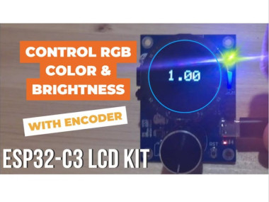
In this Visuino project, you will learn how to use the ESP32-C3 LCD kit to control an RGB LED’s brightness with a rotary encoder. Turning the encoder adjusts the brightness in steps from 0 to 1 with 0.1 increments, and the current brightness level is shown directly on the LCD display. Pressing the encoder’s button instantly sets a random LED color, making the project both fun and interactive.
This tutorial is perfect for learning how to:
- Configure and Use the rotary encoder on ESP32-C3
- Display live brightness values on the LCD screen
- Randomize LED colors with a simple button press
- Use Visuino Visual Programming to quickly design interactive IoT projects
Bring your ESP32-C3 LCD kit to life with this engaging RGB LED brightness controller!
Watch the Video!
Step 1: What You Will Need
- ESP32-C3 LCD kit
- Visuino program: Download Visuino
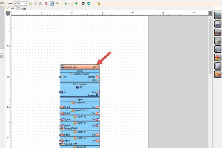
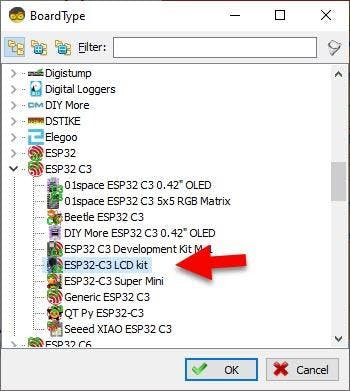
Start Visuino as shown in the first picture Click on the "Tools" button on the Arduino component (Picture 1) in Visuino When the dialog appears, select "ESP32-C3 LCD kit" as shown on Picture 2
Step 3: In Visuino Add Components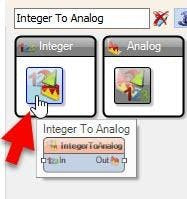
Add Integer To Analog component
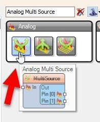
Add Analog Multi Source component
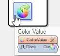
Add Color Value component
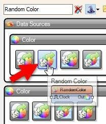
Add Random Color component
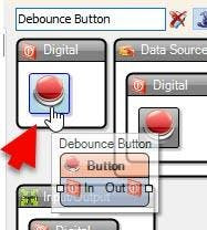
Add DebounceButton component
Step 4: In Visuino Set Components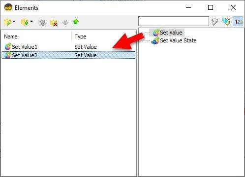
- Select "IntegerToAnalog1" and in the properties set "Scale" to 0.1
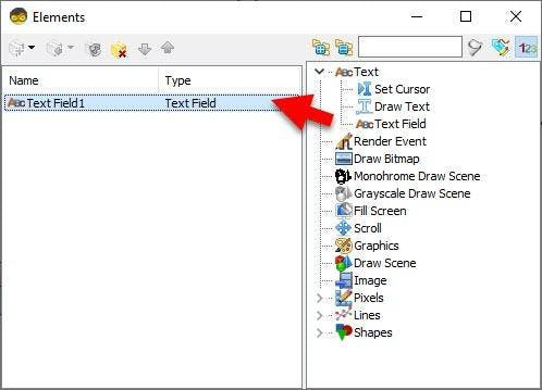
- Double click on the "Color Value" and in the Elements window add:
- Set Value
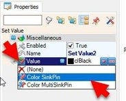
- Add another Set Value and in the properties window select "Color", click on the pin icon and select "Color SinkPin"
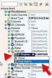
- Select "ESP32-C3 LCD kit" board and in the properties window select "Modules" > "RGB LED" > "Brightness", click on the pin icon and select "Float SinkPin"
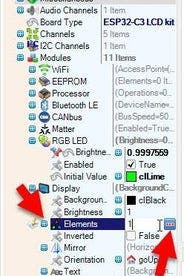
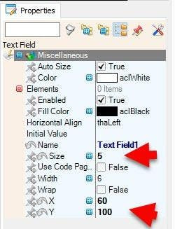
- Select "ESP32-C3 LCD kit" board and in the properties window select "Modules" > "Display" > "Elements", click on the 3 dots button and in the Elements window drag "Text Field" to the left side and in the properties window set "Size" to 5, "X" to 60 and "Y" to 100
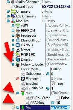
- Select "ESP32-C3 LCD kit" board and in the properties window set "Rotary Encoder" > "Max" > "Value" to 10 and "Roll Over" to False, and "Min" > "Value" to 0 and "Roll Over" to False.
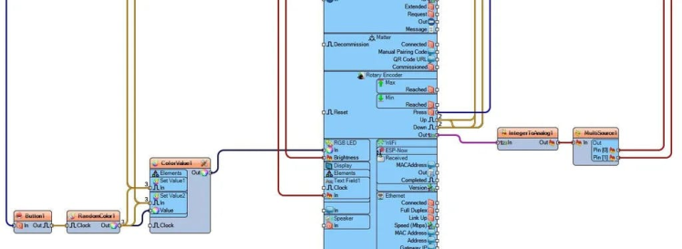


- Connect "ESP32-C3 LCD kit" > "Rotary Encoder" Pin [Out] to "IntegerToAnalog1" Pin [In]
- Connect "IntegerToAnalog1" Pin [Out] to "MultiSource1" Pin [In]
- Connect "MultiSource1" Pin [0] to "ESP32-C3 LCD kit" > "RGB LED" Pin [Brightness]
- Connect "MultiSource1" Pin [0] to "ESP32-C3 LCD kit" > "Display" > "Text Field1" Pin [In]
- Connect "ESP32-C3 LCD kit" > "Rotary Encoder" Pin [Press] to "Button1" Pin [In]
- Connect "Button1" pin [Out] "RandomColor1" Pin [Clock]
- Connect "RandomColor1" Pin [Out] "ColorValue1" > "Set Value2" Pin [Value]
- Connect "RandomColor1" Pin [Out] "ColorValue1" > "Set Value2" Pin [In]
- Connect "RandomColor1" Pin [Out] "ColorValue1" > "Set Value1" Pin [In]
- Connect "ESP32-C3 LCD kit" > "Rotary Encoder" Pin [Up] to "ColorValue1" > "Set Value1" Pin [In]
- Connect "ESP32-C3 LCD kit" > "Rotary Encoder" Pin [Down] to "ColorValue1" > "Set Value1" Pin [In]
- Connect "ESP32-C3 LCD kit" > "Rotary Encoder" Pin [Up] to "ColorValue1" > "Set Value2" Pin [In]
- Connect "ESP32-C3 LCD kit" > "Rotary Encoder" Pin [Down] to "ColorValue1" > "Set Value2" Pin [In]
- Connect "ColorValue1" Pin [Out] to "ESP32-C3 LCD kit" > "RGB LED" Pin [In]
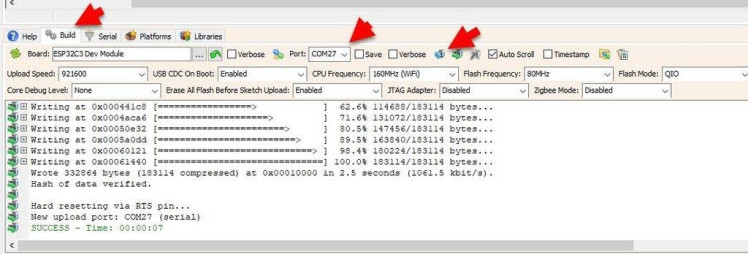
In Visuino, at the bottom click on the "Build" Tab, make sure the correct port is selected, then click on the "Compile/Build and Upload" button.
Step 7: PlayCongratulations! You have completed your project with Visuino. Also attached is the Visuino project, that I created for this tutorial, you can download it here and open it in Visuino: https://www.visuino.eu
Schematics, diagrams and documents
Code
Credits
Related products


Leave your feedback...