
Emo - Your Personal Companion Robot

Made by CodersCafeTech / 3D Printing / Displays / Kids & Family / Robotics / Sensors
About the project
An open-source personal companion robot
Project info
Difficulty: Expert
Platforms: Adafruit, Arduino, Autodesk, Microsoft, Raspberry Pi
Estimated time: 4 days
License: Apache License 2.0 (Apache-2.0)
Items used in this project
Hardware components

View all
Hand tools and fabrication machines
Story
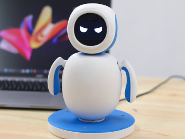
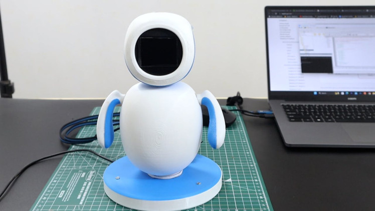
Introducing Emo, the personal companion robot that will capture your heart! With the latest Raspberry Pi 4 technology and open-source design, Emo is the perfect fusion of style and innovation. But he's more than just a robot - he's a living, breathing presence with his own unique personality and emotions.
Design
The whole design was done in Autodesk Fusion 360 and design incorporates a combination of solid and free-form modelling techniques.


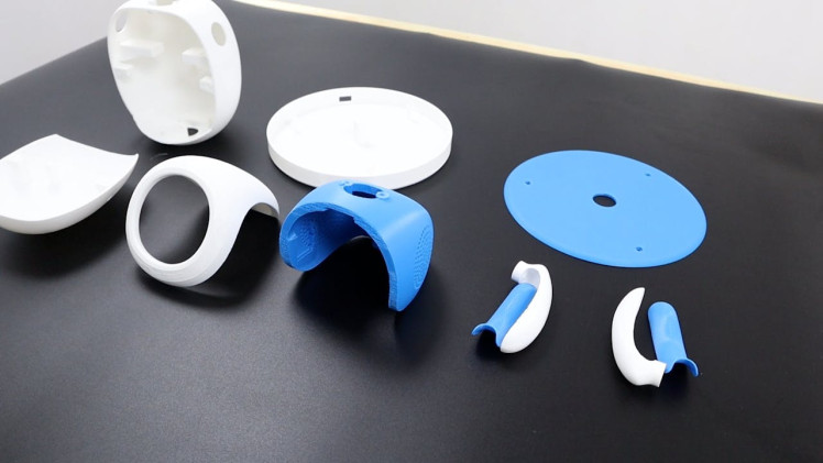
To streamline the printing process, we divided the robot body into several parts that can be easily assembled using screws.

We carefully considered the placement of the power source, situating it at the base and allowing ample space for the power cable's unrestricted movement. While addressing the cable movement was our primary concern, we also ensured that the body maintains a slight contact with the base to enhance stability during motion.
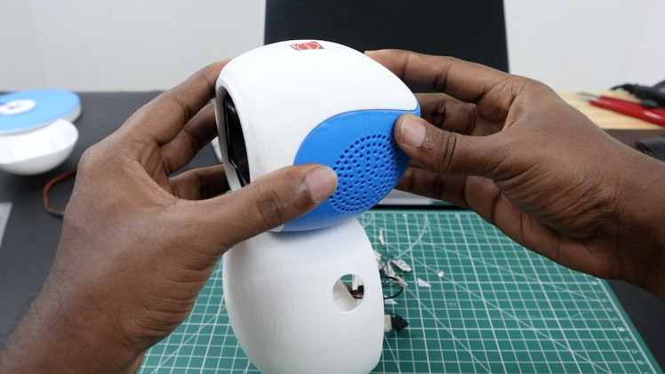
To elevate the robot's visual appeal, we chose an attractive blue-and-white color scheme.
3D Printing
Our material of choice for 3D printing was PLA, and we opted to print each component individually, resulting in a significant time investment.
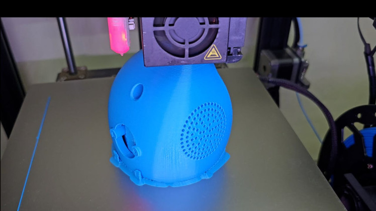
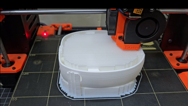
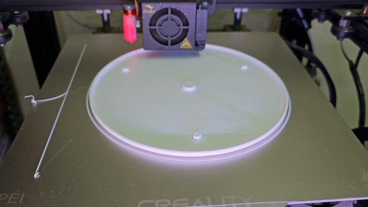
To reinforce the base's durability, we printed it using a 40% infill density, while the other parts were printed with 20% infill.
Now we have successfully printed all the necessary components, we can proceed with the assembly process.
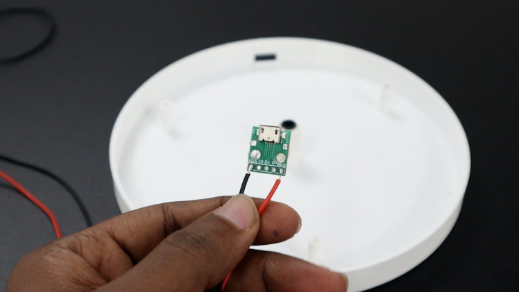
Preparing The Base
To begin the assembly, we first mounted the micro USB module onto the base section to serve as the power source for the robot.
In close proximity to the USB module, we positioned the SW-420 vibration sensor, which would detect any vibrations generated.
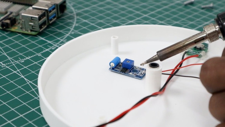
The base section consists of three wires: Vcc, Gnd, and an output wire from the vibration sensor.
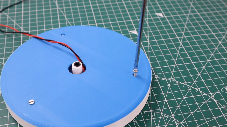
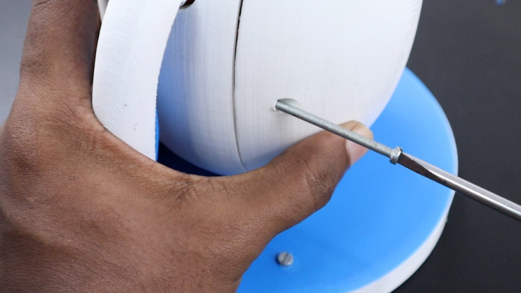
Lastly, we securely attached the lid to the base section using M3 x 10 mm screws, finalizing the assembly of the base section.
Getting The Head Ready
For touch sensing capabilities on the robot's head, we incorporated a compact capacitive touch sensor, which fits perfectly in the designated area.

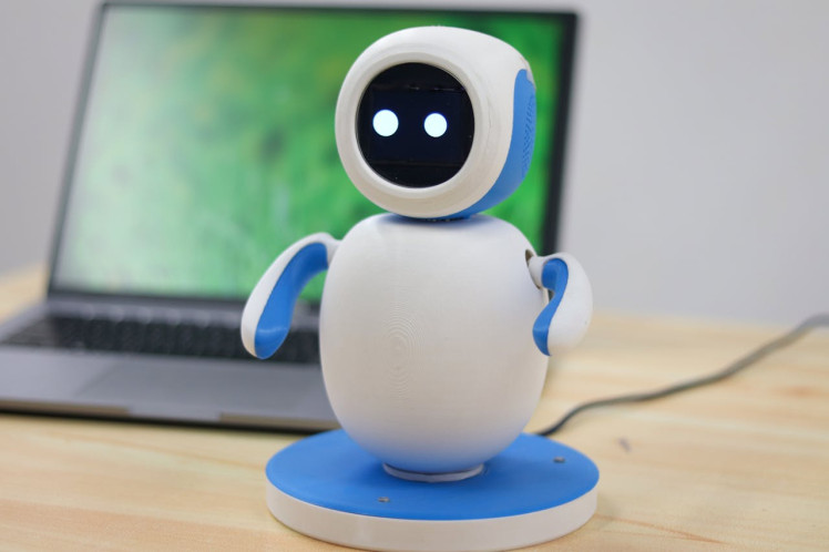
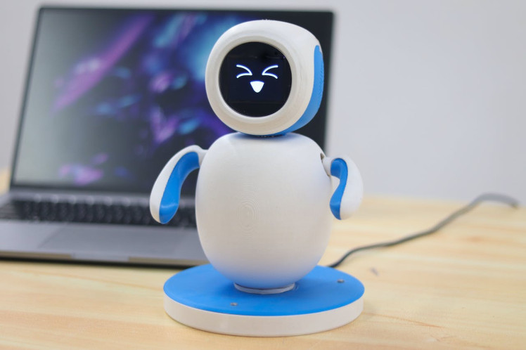
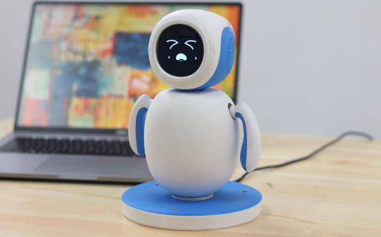
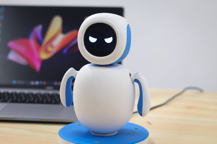
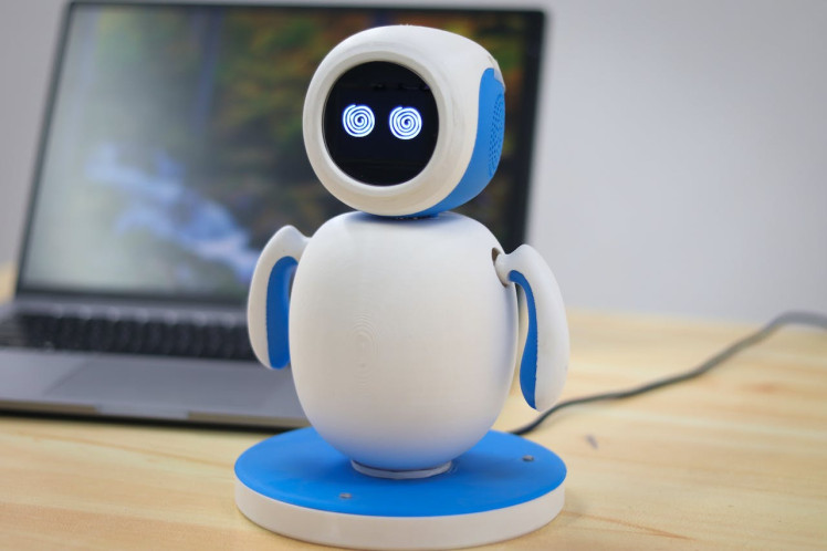
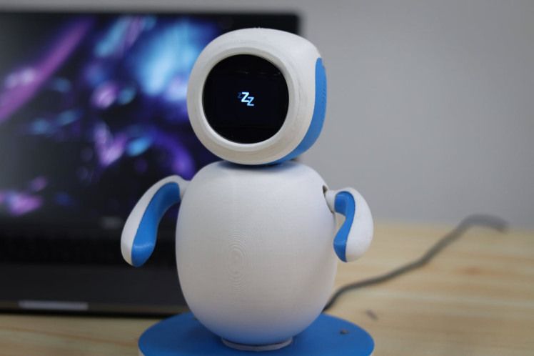
The central component of the head section is a 2-inch IPS display from Waveshare, responsible for conveying the robot's emotions. To secure the display, we utilized black supporters and a small amount of hot glue.
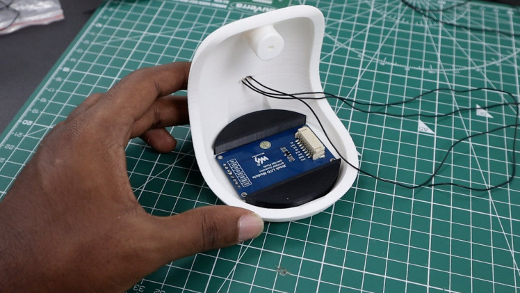
To enable audio playback, we integrated an 8-ohm 0.5-watt speaker on the left side of the head, accompanied by a PAM8403 amplifier for sound amplification from the Raspberry Pi.

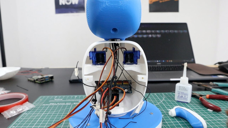
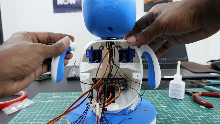
Next, we firmly attached the bottom part of the head to the robot's body using M3x15mm screws. Finally, we completed the head section by connecting and securing the previously assembled upper head part.
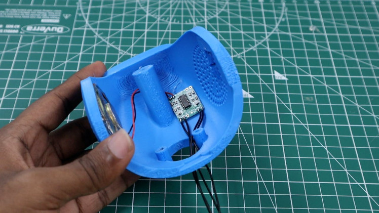
Setting Up The Body
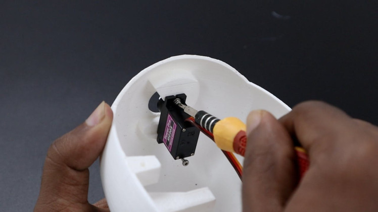
Within the body section, we incorporated three servo motors: two SG90 servo motors for the hands and one MG90 servo motor for body rotation. To conveniently control these motors, we integrated the PCA9685 - 16 Channel Servo Motor Driver.
To secure the MG90 servo motor, we utilized M2 nuts and bolts and attached it to the front of the body.
The PCA9685 was positioned in the same area to distribute the body weight evenly.
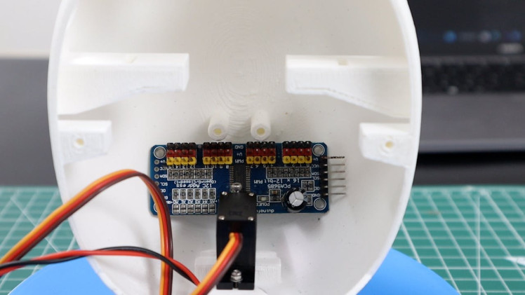
Moving on to the hands, we affixed the SG90 servo motors to both ends and carefully secured them to the servo shaft.
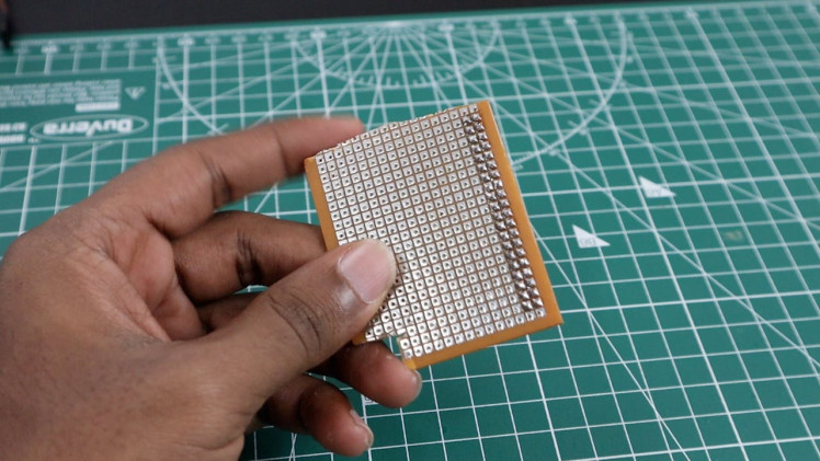
To establish connections with the Raspberry Pi, we opted for a perf board combined with a female header, offering a more organized and efficient solution than direct wire attachment. Through soldering, we ensured the components were properly connected while minimizing wire entanglement.
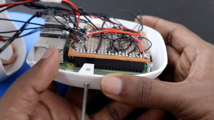
For power supply, we utilized a small male USB board sourced from an old mobile charger to provide power to the Raspberry Pi. Audio transmission was facilitated using a TRS audio jack.
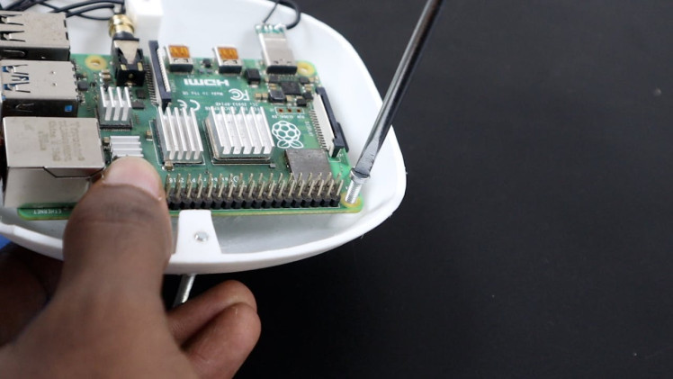
To complete the assembly, we secured the Raspberry Pi to the back of the body using screws.
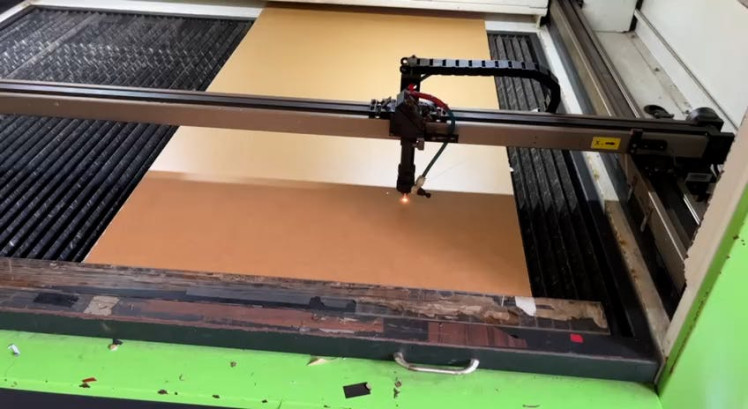
Additionally, we used a 2mm transparent acrylic sheet at the front end to conceal the gap between the outer cover and the LCD module.
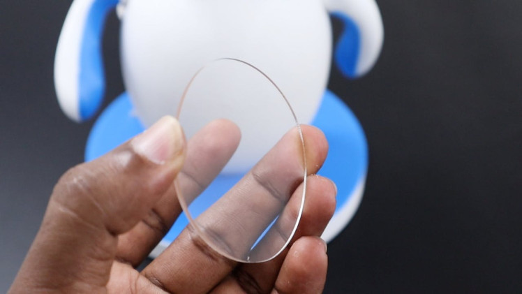
This acrylic piece was created using laser cutting technology at a local shop. We provided them with a DXF file of our design, which was obtained from the design.
Circuit
All the necessary connections for building Emo is as shown below.
 Integrating Display With Raspberry Pi 4
 Servo Driver With Raspberry Pi 4
 Vibration And Touch Sensor With Raspberry Pi
 Speaker With PAM8403 Amplifier
Calibration
After assembly, we tested all components to check whether they are working properly.
Then we started writing the code for making emotions, the emotions are constituted by servo movements and animations. To run these multiple processes simultaneously we used the multiprocessing python package.
The animations were made in adobe after effects and exported as image sequences.
So that's all about the build.
Final Results
Just plug in Emo and see the magic!
Support And Be A Catalyst
We're proud to be a team of tech enthusiasts, constantly pushing the boundaries of innovation with our exciting projects. If you're as passionate about technology as we are, then show your support by joining our Patreon or Buy Me a Coffee page
Patreon : https://www.patreon.com/CodersCafe
Buy Me a Coffee : https://www.buymeacoffee.com/coderscafetech
Feel free to check out our YouTube channel for more awesome projects:
Schematics, diagrams and documents
CAD, enclosures and custom parts
Code
Credits
Related products


Leave your feedback...