
Wireless Charging Stand - Guide

Made by ElectromakerKits / 3D Printing / Art / Kids & Family / Lights
About the project
A 3D printable, rotating, glow-in-dark double helix with intergrated QI wireless charger.
Project info
Difficulty: Moderate
Platforms: Arduino
Estimated time: 3 days
License: GNU General Public License, version 3 or later (GPL3+)
Items used in this project
Hardware components
|
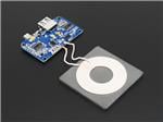
Universal Qi Wireless Charging Transmitter | x 1 |
|
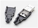
Usb Diy Connector Shell A Male Plug | x 1 |
|
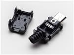
Usb Diy Connector Shell Micro-b Plug | x 1 |
|
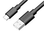
Usb 2.0a To Micro B 2.0 1.5m Blk | x 1 |
|
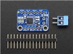
Drv8833 Dc/stepr Mtr Drivr Breakout Boar | x 1 |
|
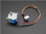
Reduction Stepper Motor 5vdc 32-step | x 1 |
|
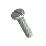
M3 6.0mm Screw Zinc Plated Steel | x 8 |

|
Metal Oxide Resistors 100 Ohm 5% 1w | x 3 |

|
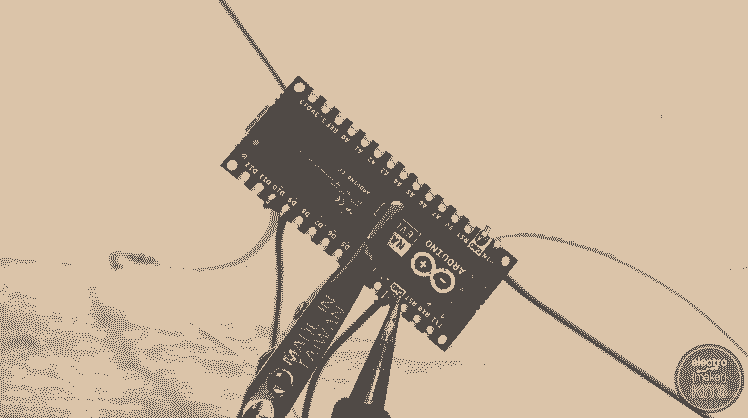
Arduino Nano Every Wo Headers | x 1 |
|
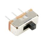
Spdt Slide Switch | x 2 |
|
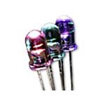
Purple Clear 2200mcd | x 4 |
|
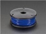
Stranded-core Wire Spool - 25ft - 22awg - Blue | x 1 |
|
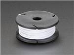
Stranded-core Wire Spool - 25ft - 22awg - White | x 1 |
View all
Hand tools and fabrication machines

|
Soldering Iron | x 1 |
|
|
3D Printer | x 1 |
Story
Printing the parts:
There are eight 3D printed parts to this project which you will need to print, the largest print is the Double Helix. I printed all the parts used in this tutorial in PLA. PETG, ABS or something similar should also be absolutely fine.

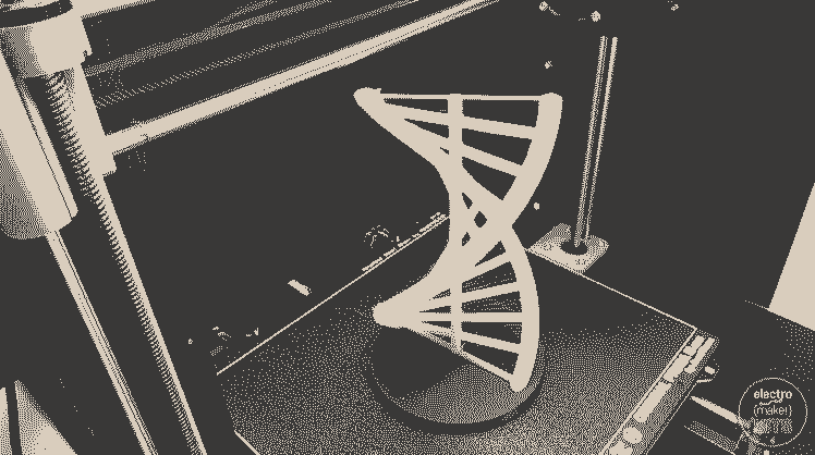
Helix.stl
Layer height: 0.15mm
Supports: No
Brim: No
Print time: about 12.5 hours
This part was printed in two different types of PLA. The first few millimetres was printed in a grey PLA which was then changed mid-print for some glow in the dark PLA. You can make the change manually on a Prusa Printer by going to ‘Tune’ -> ‘Change Filament’. You can also schedule a filament change when slicing your model and generating the GCODE for it.
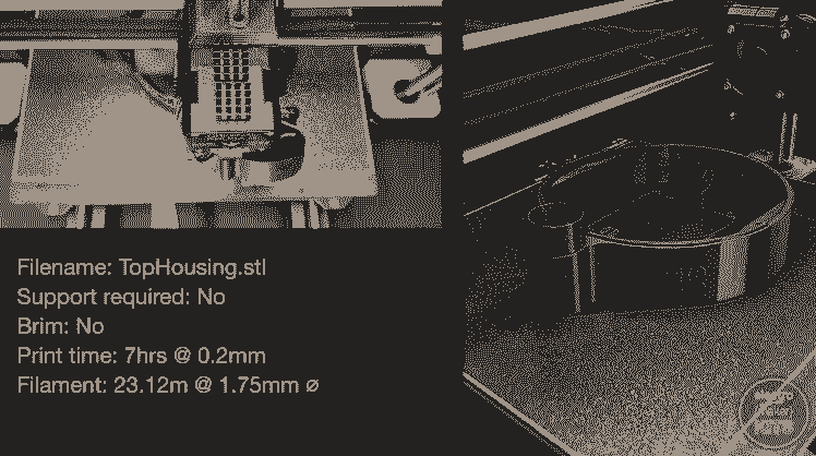
TopHousing.stl
Layer height: 0.20mm
Supports: No
Brim: No
Print time: 7 hours
This is the part we will use first during the project assembly and houses the majority of the electronics.
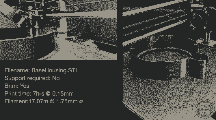
BaseHousing.stl
Layer height: 0.15mm
Supports: No
Brim: Yes
Print time: 7 hours
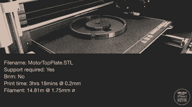
MotorTopPlate.stl
Layer height: 0.20mm
Supports: Yes
Brim: No
Print time: 3 hours 20 minutes
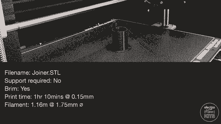
Joiner.stl
Layer height: 0.15mm
Supports: No
Brim: Yes
Print time: 1 hour 10 minutes
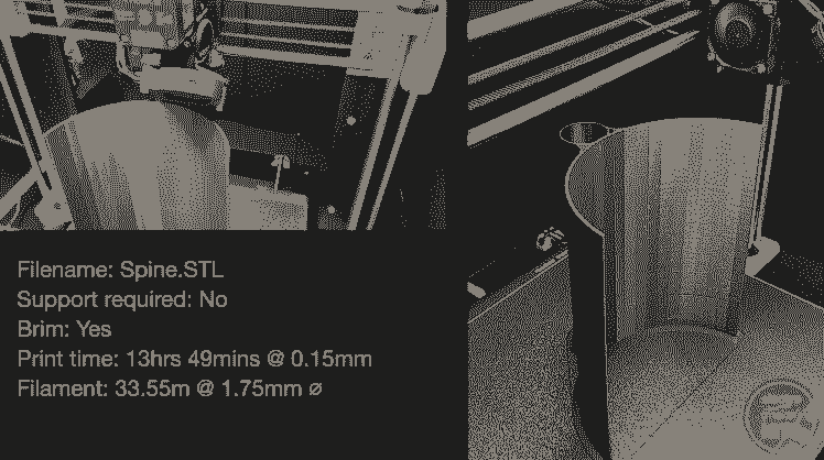
Spine.stl
Layer height: 0.15mm
Supports: No
Brim: Yes
Print time: 13 hours 49 minutes
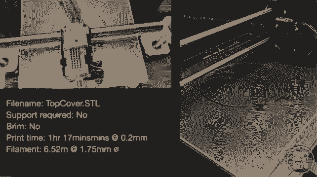
TopCover.stl
Layer height: 0.20mm
Supports: No
Brim: No
Print time: 1 hour 17 minutes
Begin assembling the Electronics
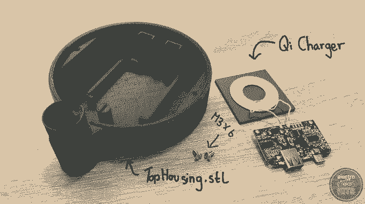
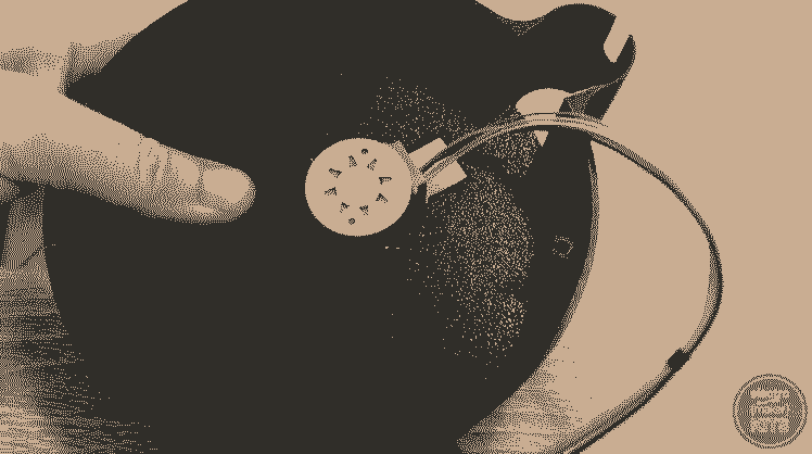
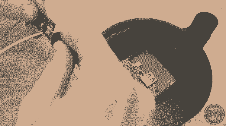
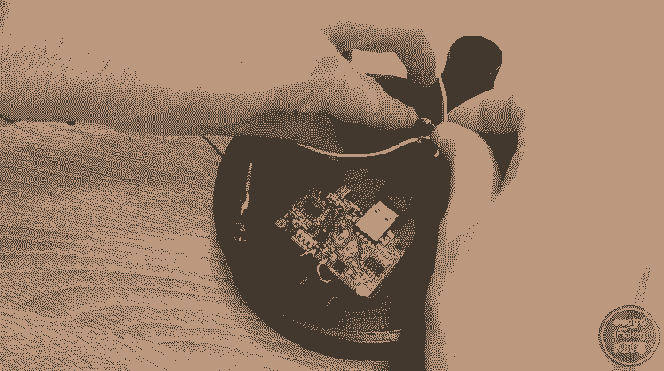
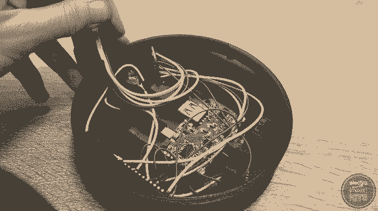
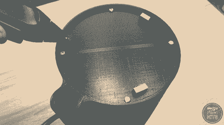
We’ll start the assembly by installing the QI charger into the top housing.
Place the coil face down in its holder and use a few dabs of hot melt glue to keep it in position against the print.
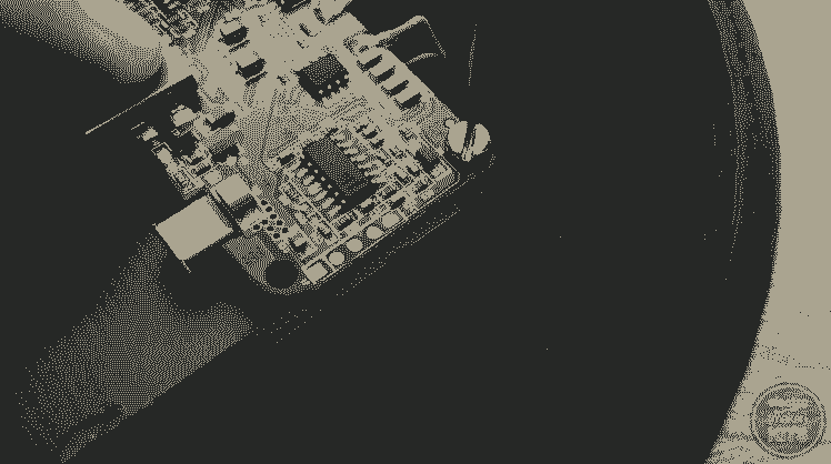
Once the glue has cooled you can fold the circuit board carefully back over the rear of the coil and hold this in position by using two of the M3 x 6 screws in your kit. These need to be done up firmly, but be careful not to over tighten them.
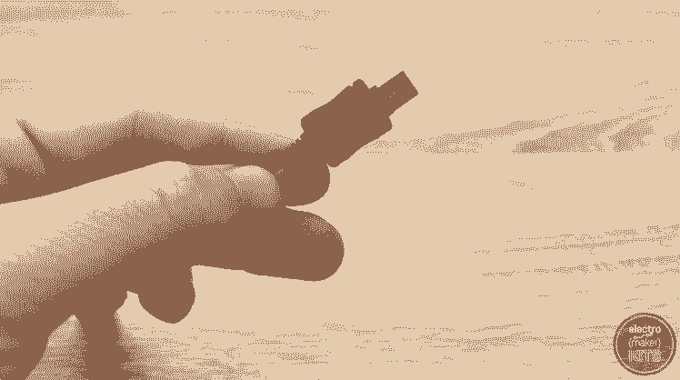
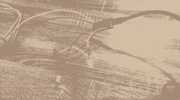
Now we will create our own mini USB cable to connect the power from the QI charger to our Arduino board.
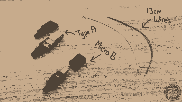
Prepare two 13cm lengths of wire and the Type A Male Connector and Type Micro B Male connector for this step.
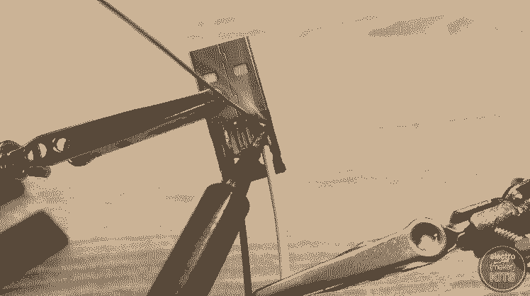
With the pins of the Type A connector facing you and the USB plug away from you solder the grey wire to the pad on the left and the white wire to rightmost pad.
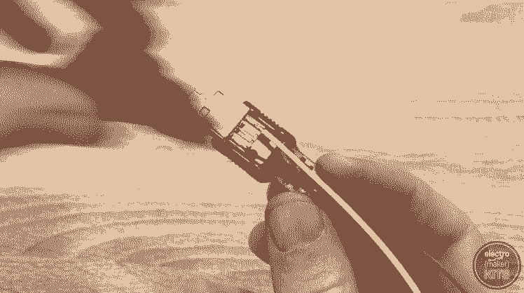
You can then finish the assembly of this end of the cable by push fitting the two plastic halves of the connector around the electronics.
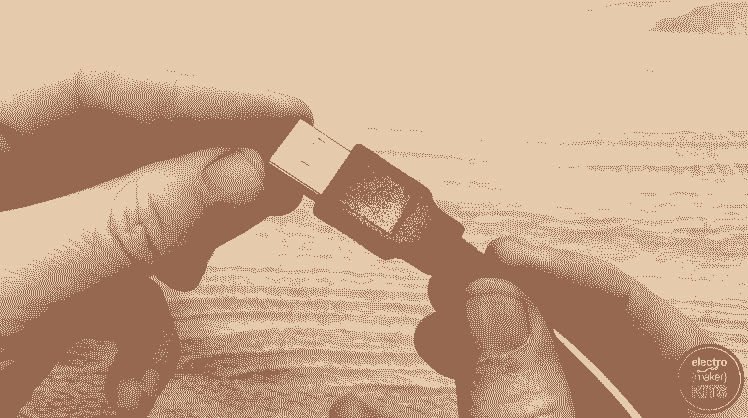
Before we solder the other end you’ll need to take the small rubber sleeve from the Micro B connector and thread both the wire through it.
Start Soldering

With the micro B plug facing away from us and the side with three pads on it (not the side with two) facing upwards the grey wire is soldered to the left hand side and the white wire to the right hand side.

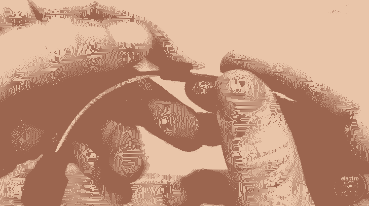
You can now slider the small rubber collar we put the wire through back up to meet the plug and then encase these in the two rigid halves of the plugs shell.
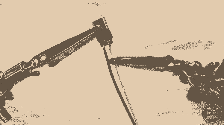
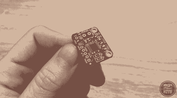
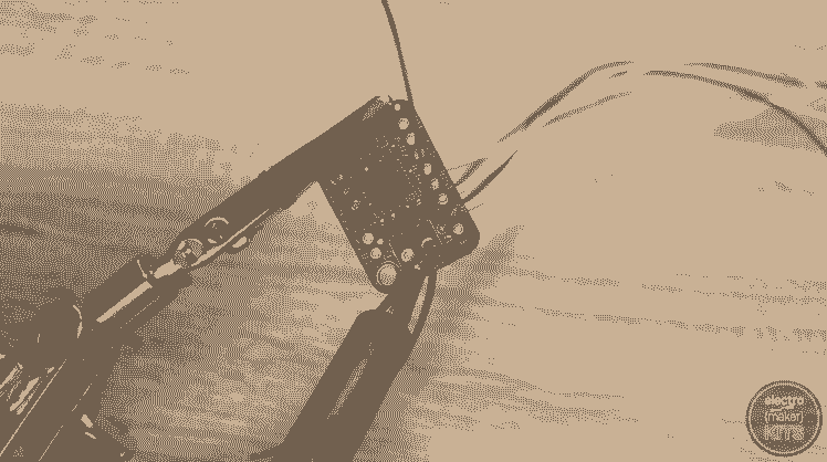
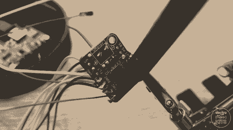
For the next step prepare five 40cm lengths of wire and your motor driver board.
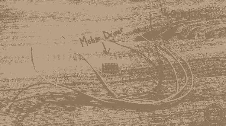
Solder one end of each wire to following points on the board:
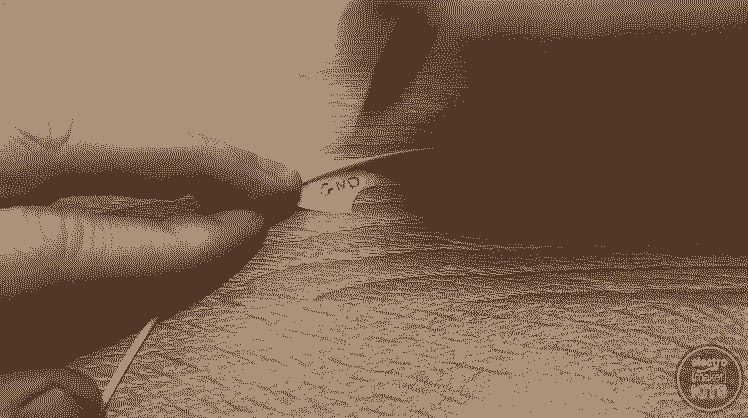
Ground
BOUT1
BOUT2
AOUT
AOUT2
Then use some masking tape or similar to label the other end of each wire. This will make it a lot easier to connect it to the stepper motor towards the end of this project.
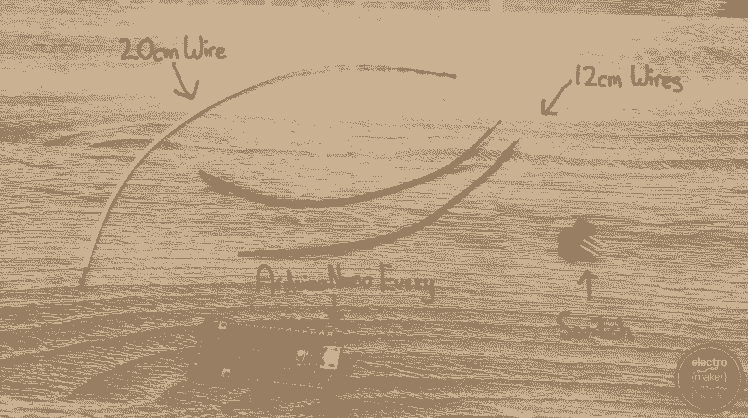
Prepare two 12cm lengths of wire, a 20cm length of wire, one of the switches and the Arduino Every board for this step.

Solder one of the 12cm wires to the positive side of VMOTOR. The other end of the wire is soldered to one of the outside legs on the switch.

To the centre leg of the switch solder the other 12cm wire. Solder the other end to the VIN pin on the Arduino.
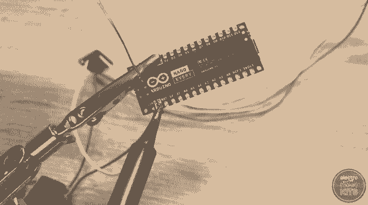
The 20cm length of wire is soldered between the negative side of VMOTOR on the motor shield and one of the GND connections on the Arduino.
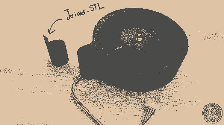
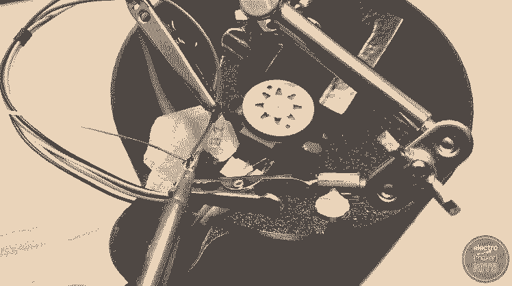
Let’s begin to work on the base of the project. You will need the ‘Base Housing’ print, ‘Joiner’ and ‘Motor Top Plate’.
Install the stepper motor
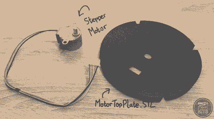

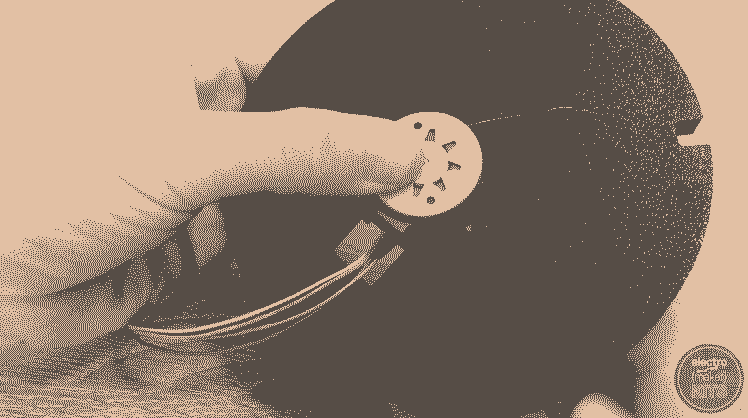
Taking the stepper motor and ‘Motor Top Plate’ to begin, apply plenty of hot melt glue to the recess shaped for the stepper. Insert the stepper motor (ensuring that you don’t get any glue on the shaft) and press firmly against the printed part so that it is level as the glue cools.
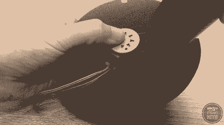
Once the glue has cooled you can add some more to the rear of the tabs to help ensure it stays in place. This glue will be taking the weight of the double helix once the project is complete.

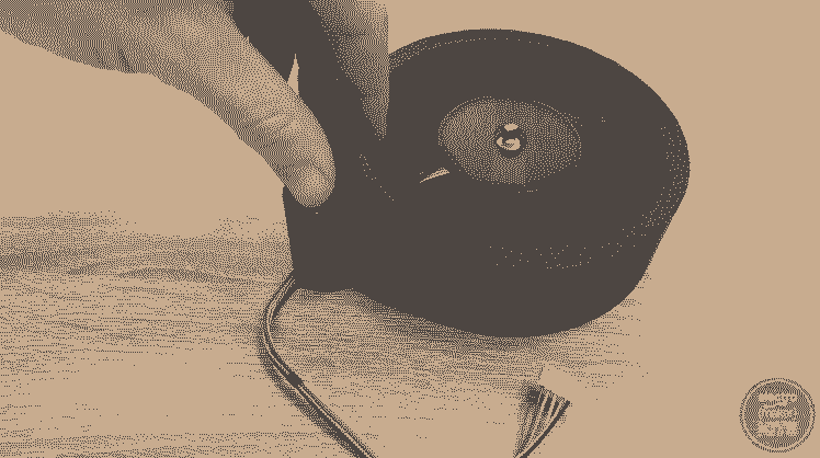
Add glue to the underside of the rim of the ‘Base Housing’ print. The ‘Motor Top Plate’ assembly is then inserted from below. Again push these two prints firmly together so that everything sets level.
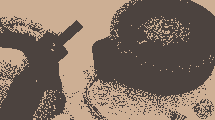
Apply a small dab of glue the outside of the ‘Joiner’ print and insert this into the assembly we have just been working on. The long rod end is inserted first and the shape of the part will ensure it is inserted in an orientation that will not block any cable runs which we will be using later. Insert it all the way in until the part touches the table.
Resistors, wires, switches and LED's

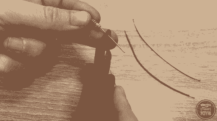
For this step prepare two 10cm lengths of wire and two 100 ohm resistors. Reduce the length of the legs on the resistor by cutting two-thirds off from each side.


Solder one wire to one resistor and repeat with the other pair.
Solder one of the wires to D9 and the other to D10 on the Arduino.

Trim off about one-third of the length of both legs on two LEDs. Take note of which leg was the longest of the two before you cut it and ensure it still is after you have cut it. This will help us identify which one is the anode (positive) end later.

Solder the longer and leg of each LED to each of the two resistors.

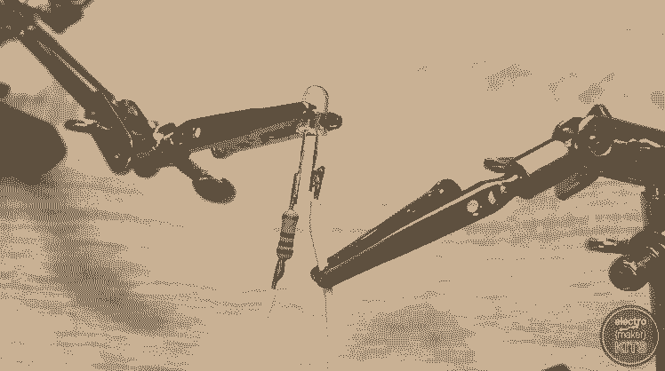
Now prepare two more wires, one 5cm long and the other 12cm long. Solder one to the unused leg of one of the LEDs and repeat with the other LED and wire.

Solder both the wires to the same outside leg of a new switch.
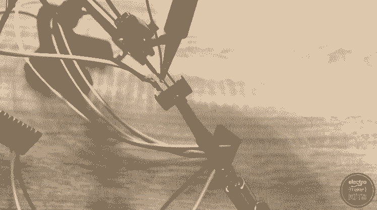
Attach an additional 10cm length of wire to the centre leg of this switch, and then solder the other end to GND on the Arduino.
Check the code
Now is a good time for us to upload the code and check some of our wirings so far. Connect your Arduino to your PC using the included USB cable and open the project's code in the Arduino IDE. There is a link to download the code towards the bottom of this page. (Or at the projects page on electromaker.io if you are reading a printed copy of these instructions).
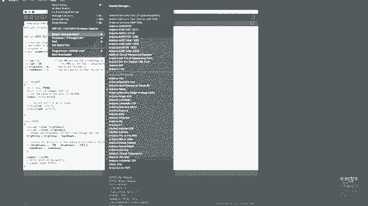
If you have not used an Arduino Nano Every board before then you will most likely need to install the board in your IDE. This is as simple as opening the ‘Tools’ menu, then ‘Boards’ and clicking on ‘Board Manager’ at the top of the fly-out list.
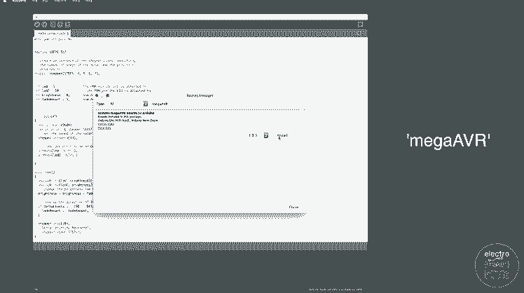
In the board manager that pops up, search for ‘megaAVR’ and install the latest version.
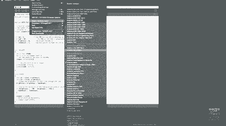
Go back to the Tools menu and ensure that the board type of ‘Arduino Nano Every’ is selected and that you have chosen the serial port which is connected to your Arduino.
Upload the code and if everything is correct the LEDs should begin to fade in and out slowly. If not, try the switch connected between the LEDs and the ground on the Arduino.
Final steps
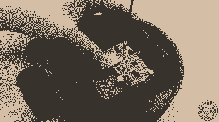
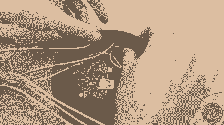
Plug one end of the USB cable you assembled earlier into the Arduino and the other end into the QI charger module.
Add some hot melt glue to the top of the level split column and the take the LED with the longer wires attached and attach it to the top of the column. You can carefully separate the legs of the LED to help it fit on the column and prevent it from short-circuiting
Repeat the same with the LED, but this one is fitted on the sloping face of the remaining split column.
Use more glue to fix the switch for the LEDs at the top of one of the U shaped columns. The top of the switch should be flush with the top of this column. Take care that glue does not prevent the switch mechanism from actually switching.

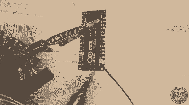
Prepare five 18cm wires and solder one to each of the following points on the motor driver.
AIN1
AIN2
SLP
BIN2
BIN1
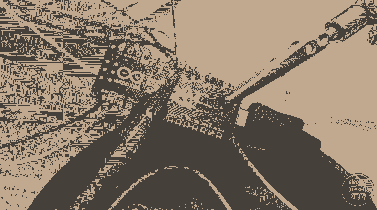
The wires are then soldered onto the Arduino Nano Every as follows:
AIN1 —> D5
AIN2 —> D4
SLP —> 3.3V
BIN2 —> D7
BIN1 —> D6
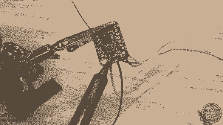
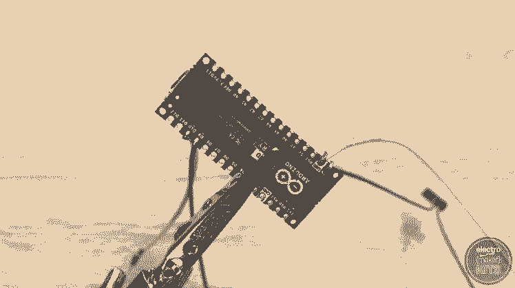
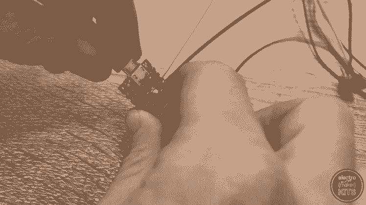
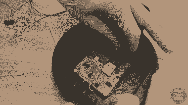
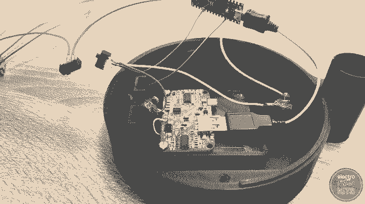
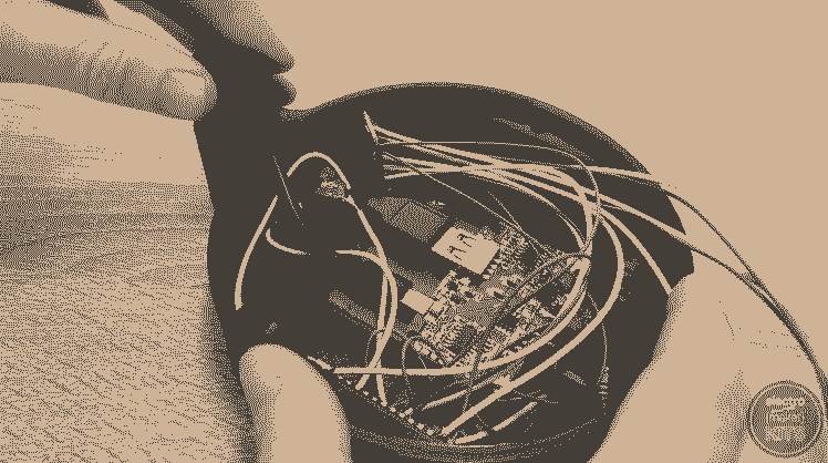
Apply a generous helping of glue to the rear-side of the Arduino and fix it in place on one side of the enclosure.

Glue the remaining switch to the unused switch holder. As before ensure that the switch is flush with the top and glue does not interfere with its operation.
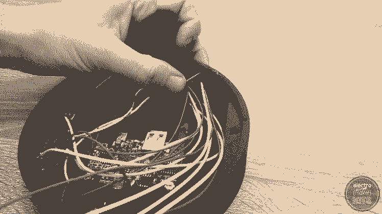
Use another liberal helping of glue to fix the motor driver into place. I put glue on the bottom of the enclosure and sidewall to hold the driver in position.
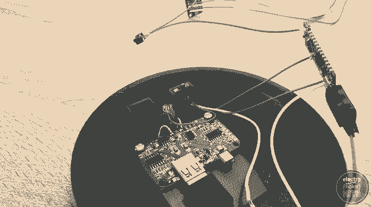
Connect the factory-made USB cable to the QI charger and route the cable through the outlet at the rear of the enclosure. Route the unconnected wire coming from the stepper motor along the same path as well.
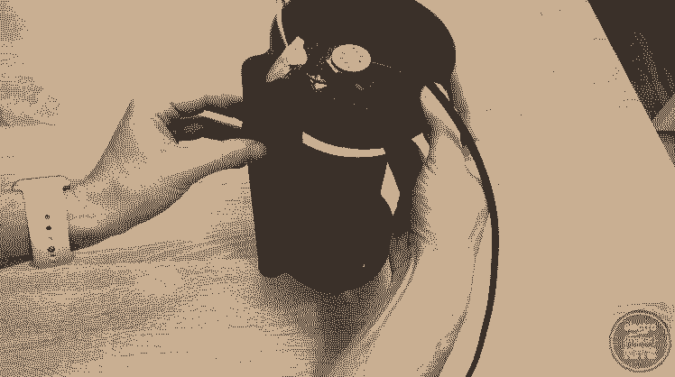
The top cover can then be seated in the enclosure and screwed into place using two of your M3 x 6mm screws.

Thread the USB cable and stepper wires through the tunnel at the rear of the spine. This can then be fitted together.
Thread the cable through the tunnel at the rear of the base housing and fit these parts together.

To connect the stepper motor remove the plug at the end of its wires and strip their ends in preparation for soldering.
These are then soldered onto the labelled wires we have coming from the stepper motor driver board. They are to be connected as follows:
Red —> Ground
Pink —> AOUT2
Yellow —> BOUT2
Orange —> AOUT1
Blue —> BOUT1
Finishing up
Wrap some insulation tape around each of the solder joints (or use shrink wrap if you prefer) to prevent them from shortening the circuit.

The bottom cover can now be added and secured into place with the four remaining screws.
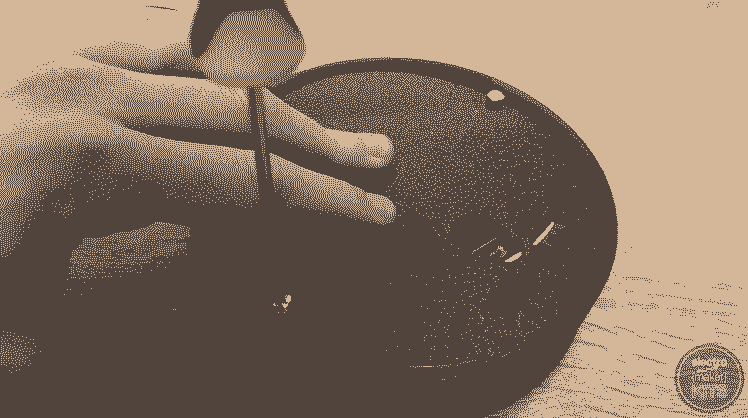
To help reduce noise from vibrations, cut three small lengths of a rubber band and glue these to the three feet.
The double helix that we printed earlier is added to the shaft of the stepper motor by aligning the shape on the bottom of the 3D print with the shaft itself. It will only fit when the two are parallel.
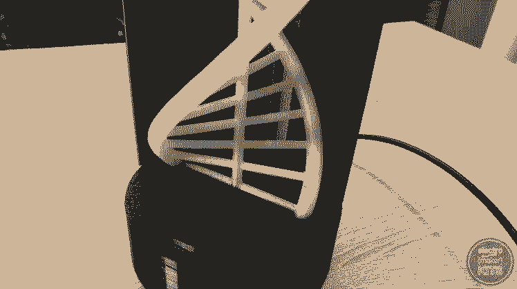
As long as it is well balanced the only thing the 3D printed helix part should come into contact with is the shaft of the stepper motor. If you hear any scraping noises check that the edges of your prints are clean of any stray plastic and that the helix is well balanced.
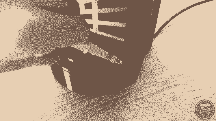
If you wanted to as an optional step you can apply some super glue to between the spine and the top and bottom housings.
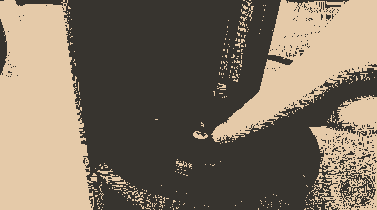
Project complete! The wireless charger embedded in the top is QI certified so any QI compatible device can be charged. I’ve used mine to recharge my mobile phone and one of my filming lights which has a wireless QI receiver inbuilt.
The two switches on the underside of the top housing let you turn on or off the LEDs and motor separately.
If you want to customise yours then feel free to design other objects to put on the turntable. Perhaps you could make a glow in the dark skeleton?
Schematics, diagrams and documents
CAD, enclosures and custom parts
Code
Credits
Related products


Leave your feedback...