
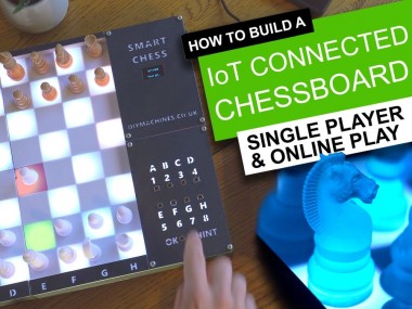
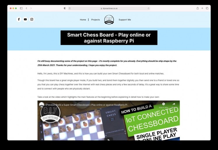
Diy Super Smart Chessboard | Play Online Or Against Rasp Pi

Made by DIY-Machines / 3D Printing / Communication / Games & Gaming / Kids & Family / IoT
About the project
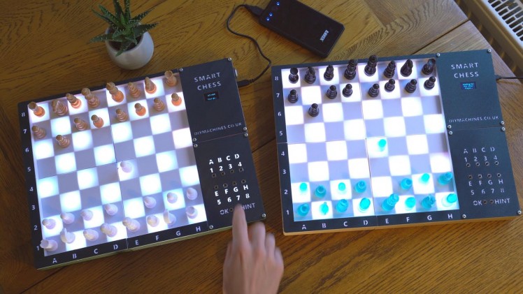
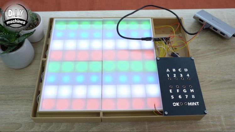
A 3D printed, low cost chessboard. Play online or against inbuilt Raspberry Pi. It tells you when you break the rules and can suggest your next best move for you. Great for learning. Powered by USB battery pack for portability.
Project info
Story
Hello, I’m Lewis and this is how you can build your own Smart Chessboard for both local and online matches.
Though this board has a great single player mode, If you build two, and bond them together digitally you can then send one to a friend or loved one so you that you can play chess together over the internet with real chess pieces and only a few seconds of delay. It’s a great way to share some time and to connect with people who are physically distant.

Step 1: Video of the Project
Take a look at the video which highlights the main features at the beginning before explaining in detail how to make your own. Don't worry though, if you prefer a written tutorial then you are in the right place.
Here are a few more features:
- Check your moves are legal and warn you when you don't play by the rules
- Suggest what would be a good next move for you
- Entirely 3D printable including the chess pieces
- Very cool looking LED lighting to convey the game status and provide the lighting for evening games
- Smart control panel which guides you through how to use the board with intelligent backlighting
- Small and low cost OLED screen to help guide you through using it
- Powered by USB, so you can connect it to mains or run it from a common USB battery pack for untethered play
The internet connectivity, computer opponent and rule checking are handled by a Raspberry Pi, whilst the lighting and buttons are taken care of by an Arduino Nano.
Step 2: BOM (Bill of Materials)
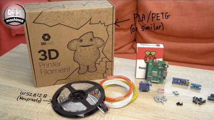
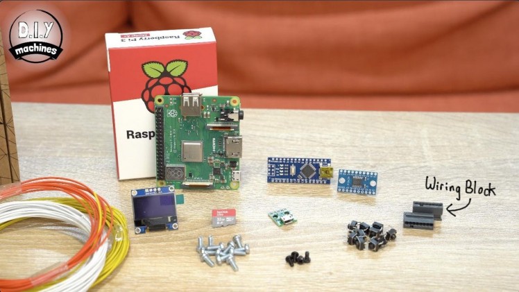
When designing this project I tried to keep the cost down and the number of bought parts low. This is helpful if you want to make more than one.
List of items used in this project and where to find them:
- (x86) Neopixels/WS3212b on a 30 per meter roll. - https://geni.us/5mWS2812B30m
- (x10) 6x6x5mm tactile momentary push buttons - https://geni.us/6x6TactileButton
- (X1) Arduino Nano - https://geni.us/ArduinoNanoV3
- (X1) Raspberry Pi (Zero can cope but recommend model 3 A+) - https://geni.us/RaspberryPiAPlus
- (X1) Micro SD Card 8Gb or higher for Raspberry Pi - https://geni.us/Micro-SD
- (X1) Logic level shifter - https://geni.us/TXS0108E-Shifter
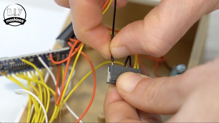
- (x2) Wiring blocks for at least 6 wires each. I used the Wago 243 series - https://geni.us/Wago-243
- Some Wire - https://geni.us/22AWGWire
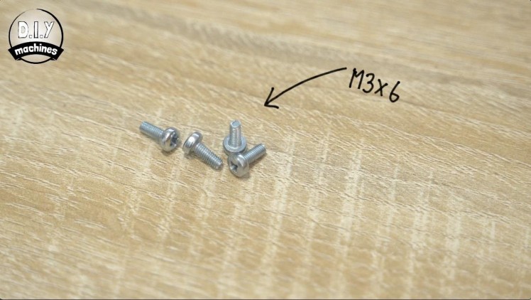
- (x12) M3x6mm bolts - https://geni.us/NutsAndBolts
- (x4) M2.5 x 6mm bolts (for securing Raspberry Pi) - https://geni.us/PiBolt
- Some plastic for the printed parts (I used PLA, including this wood infused lumberjack from 3D Jake who kindly help support my project) - https://www.3djake.com
- (x1) USB female DIP board - https://geni.us/FemaleMicroUSBDIP
- (X1) 0.96 Inch OLED screen - https://geni.us/0-96OLED
Step 3: Downloads:
The 3D printable parts can be downloaded with each step as you go through this guide.
The code for both the Arduino and Raspberry Pi can be downloaded for free from my website: https://www.diymachines.co.uk/smart-chess-board-w...
I've not duplicated the code here on tutorials so that I can easily keep it up-to-date in one place. :)
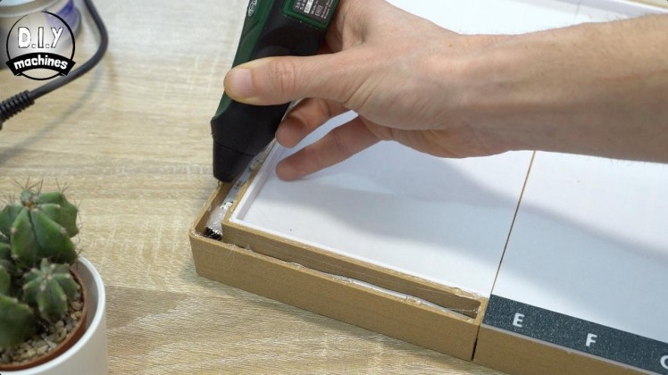
Step 4: Printing and Gluing the Frame

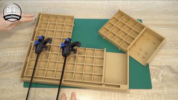
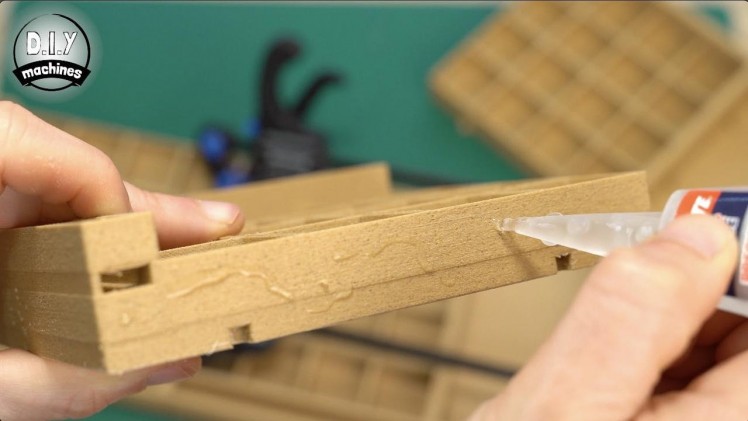
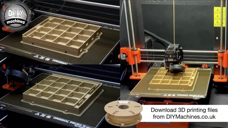
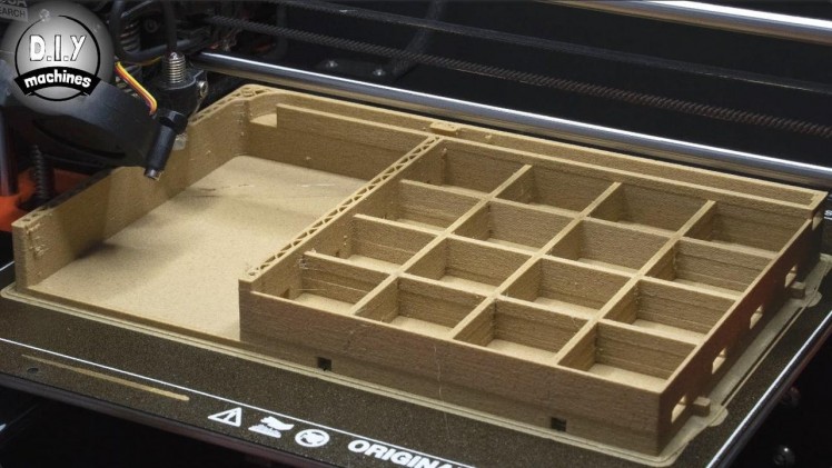
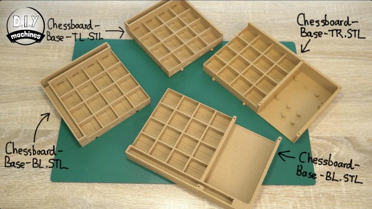
The first part you need to print is the main frame of the chessboard. It is broken into four separate prints which are glued together. Each one has a 'key' to help make alignment much easier.
The filenames to print are:
- Chessboard-Base-TL.stl
- Chessboard-Base-BL.stl
- Chessboard-Base-TR.stl
- Chessboard-Base-BR.stl
I printed all of mine in PLA and used a brim on all the parts to help ensure good adhesion to the print bed. There is no need to add supports for any of the parts in this project - I designed them all to print just fine without supports. :)
Once printed they can be glued together. I recommend using a strong glue (something like a 5 minute epoxy might be best) and ensure they are held tight together as the glue dries. I used some small clamps. You may also fine it easier to insert the last of the four corners from underneath.
Step 5: Wiring Diagram
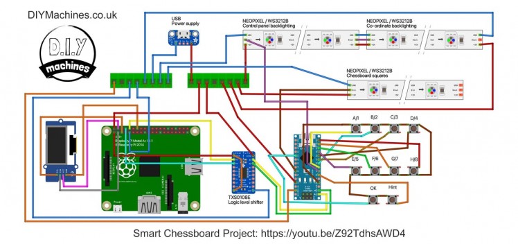
Before I forget I should mention that I have created a wiring diagram if you like to refer to one whilst working. I have attached it to the images for this step.
Step 6: Preparing the Playing Surface LEDS


For this step you will need:
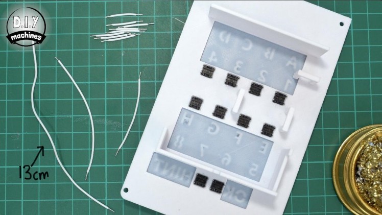
- Your roll of RGB LEDs
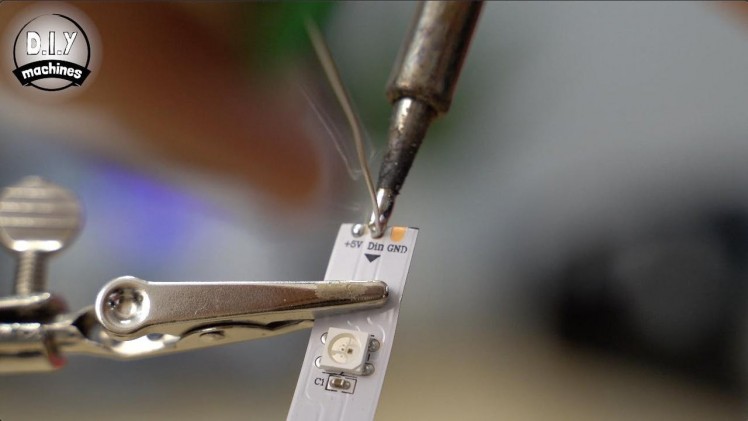
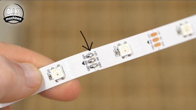
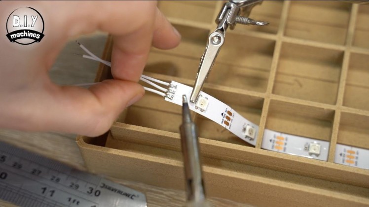
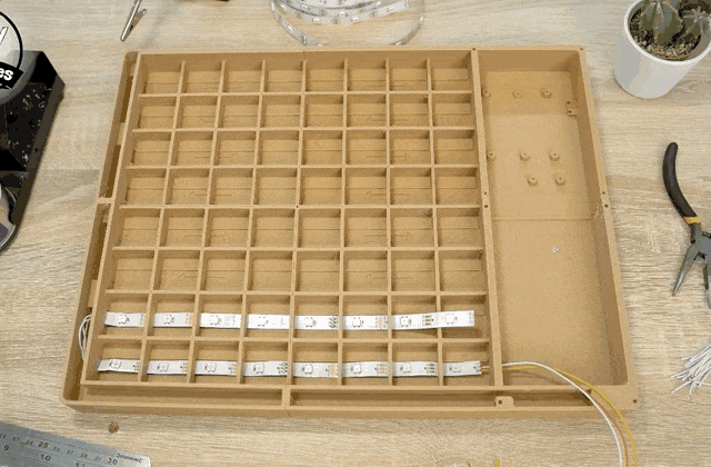
We need 64 LEDs, one for each square of the playing the surface. From your roll of WS2812b LEDs trim off eight lengths of eight LEDs. You can cut through them where indicated with a standard pair of scissors. Don't worry if you see some solder where you need to cut, it is fine to cut through the solder and the pads like all the other cuts.
Next, 'tin' the three pads at both ends of all eight strips. (This means apply a small deposit of solder onto each pad). This will make it easier to solder wires to them in the next step.
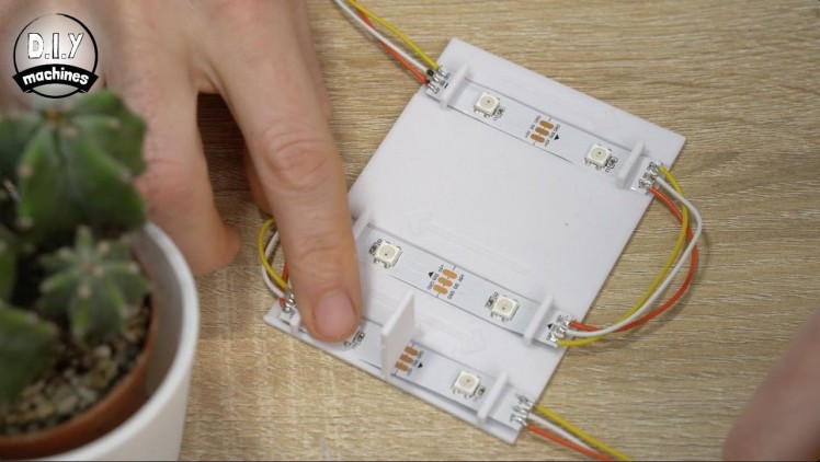
Step 7: Installing the First Surface LEDs


For this step you will need:
- Some electrical wire
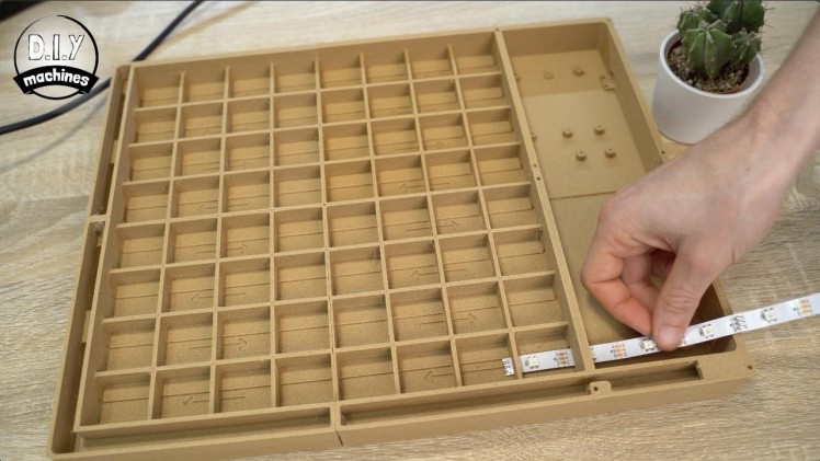
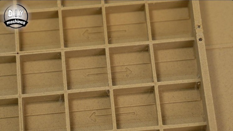
Whilst installing the LED's into the main framework of the chessboard it is important that we connect them in the correct direction.
On the 3D printed chessboard you will find some arrows I added into the design. You will also find some arrows drawn onto the surface of the strips of LEDs you have been preparing. When we install the strips the arrows on the LEDs and 3D print need to be going in the same direction.
The arrows represent the direction that the data for controlling the LEDs is passed from one emitter to the next. If you wire a strip in the wrong direction somewhere then they will not respond correctly (if at all) from that point on in the chain.
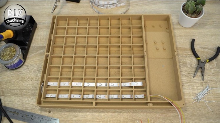
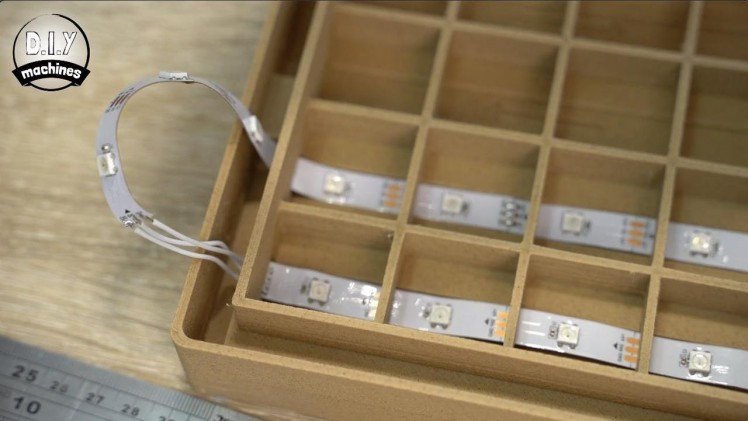
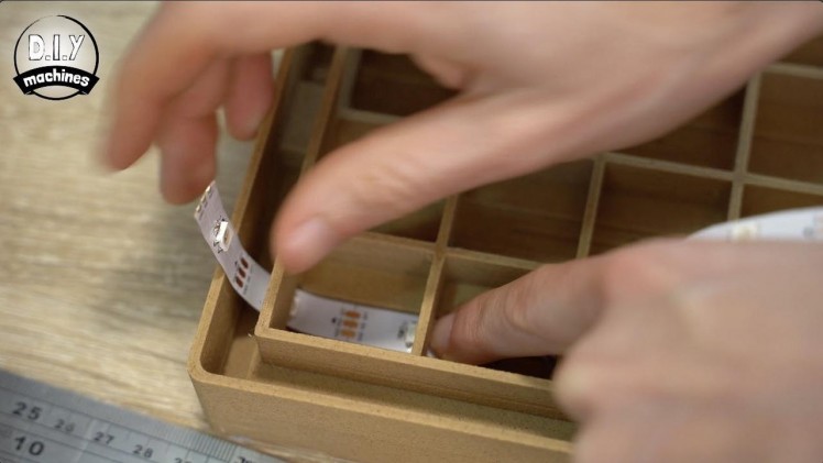
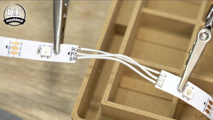
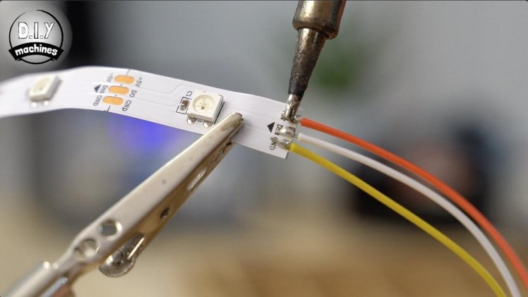
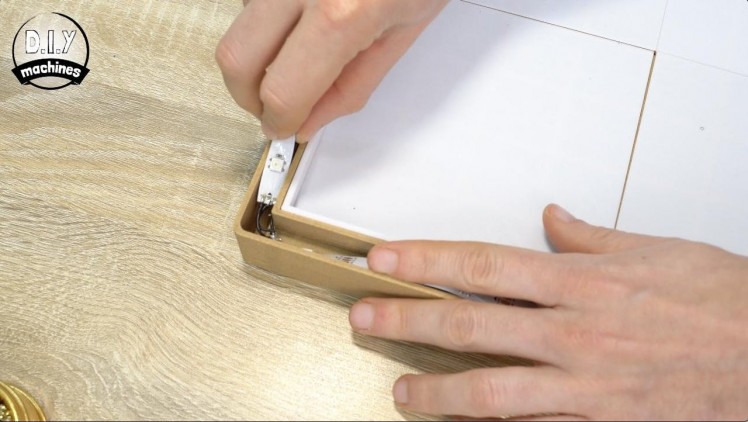
You should solder three 28cm long wires to the incoming end of one of the strips of LEDs. This first strip can then be slid into position from the bottom right whilst be careful not to catch the LEDs as they pass through the board.
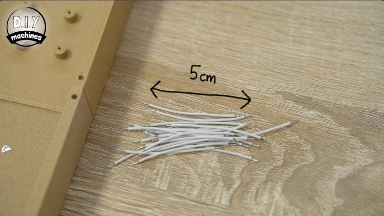
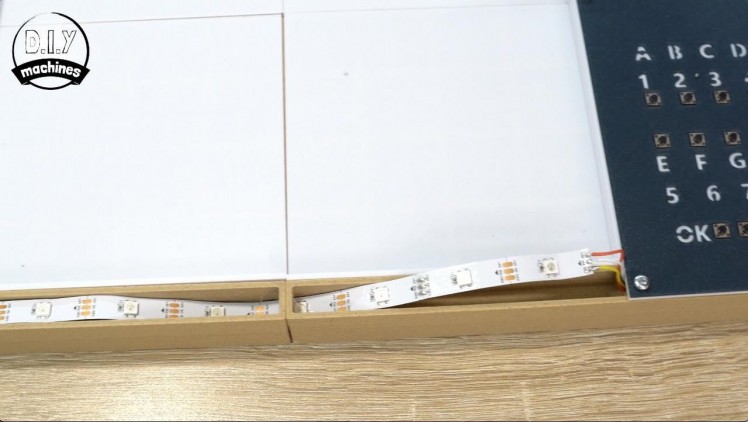
We will use sets of 5cm long wires to join each strip as we zig zag up through the chessboard. I suggest you prepare 21 5cm wires and tin there ends, then you can concentrate on the LED's strips as you go.
Solder three of the 5cm wires to the other end of our first LED strip. Another strip of LEDs is then attached to the unconnected ends of these wires. This strip is then passed through the tunnel of bridges, up out of the board through the long opening on the left before being gently turned by hand and reinserted into the next row heading back in the opposite direction. Check the last few images if you are unsure of what I'm trying to describe. :)
Step 8: Installing the Remaining Surface LEDs
For this step you will need:
- Some electrical wire
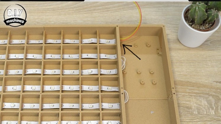
This pattern of connecting three 5cm long LEDs, followed by another strip repeats all the way until the last row at the top of the board.
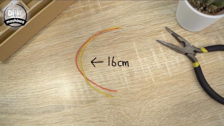
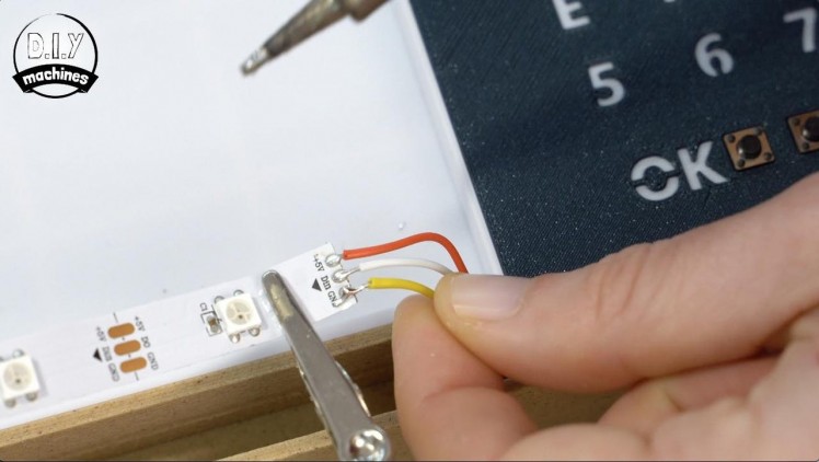
For the end of the last row you should connect two 16cm long wires. These should be connected to the just the two power pads marked as 5v and GND/-. (This is to help avoid any noticeable voltage drop along the length of LEDs.)
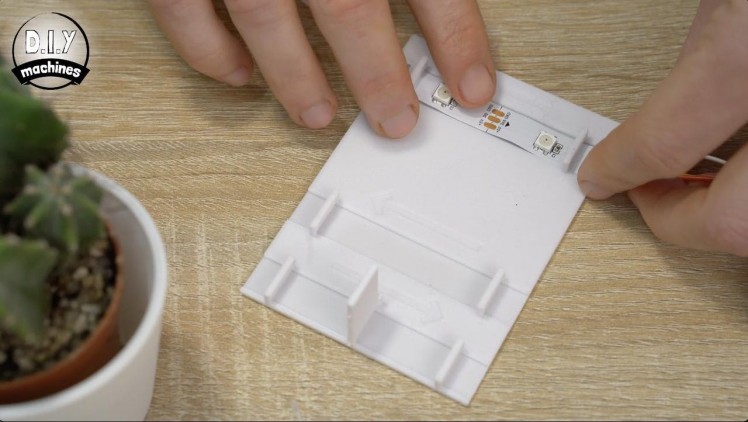
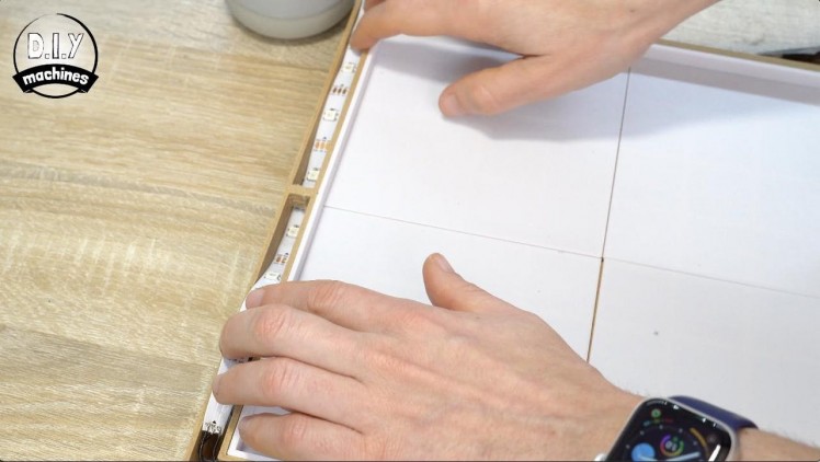
Step 9: Adding the Playing Surface
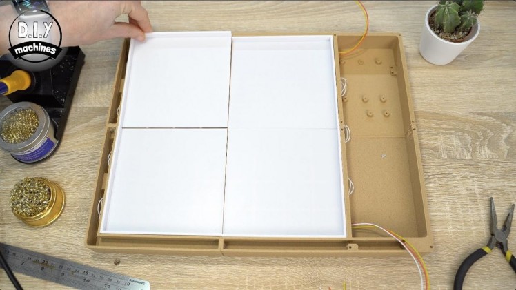
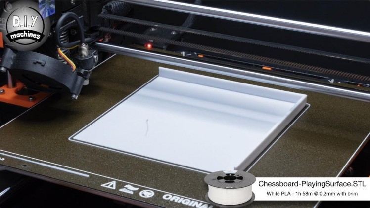
The playing surface is printed in white PLA and you will need to print four of them. A neutral colour should be used to allow the light from the LED's to be diffused and pass through. The part is called 'Chessboard-PlayingSurface.stl'.
Once printed they can be simply placed in position for the time being. They will be fixed in place much later in the build.
Step 10: Fitting Buttons the Control Panel
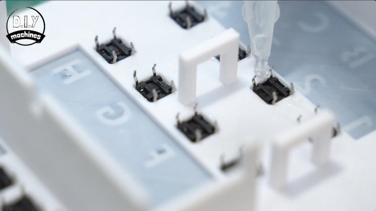
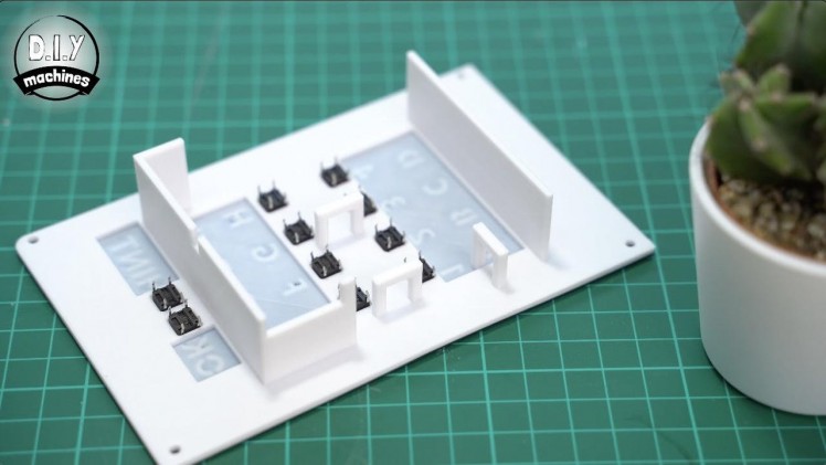
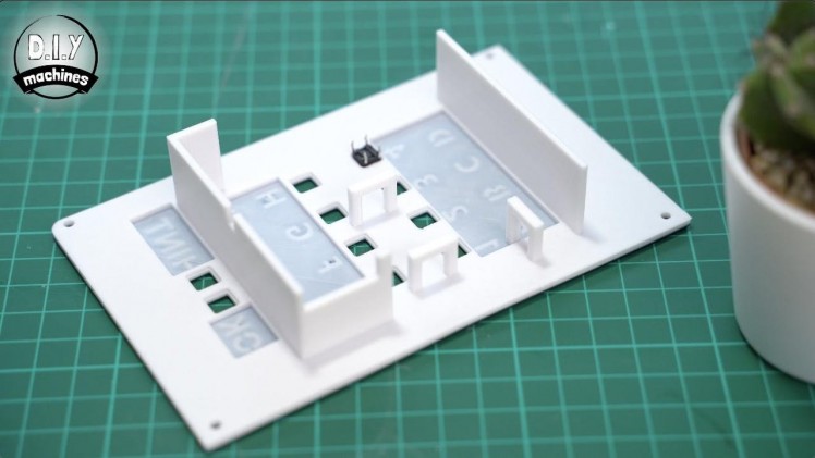
For this step you will need:
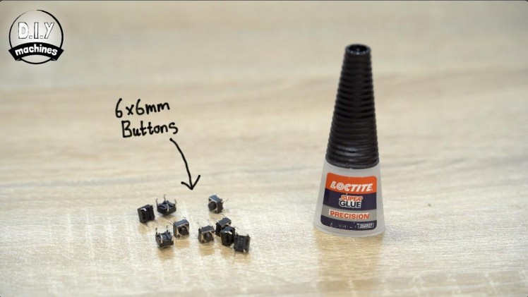
- Tactile buttons (x10)
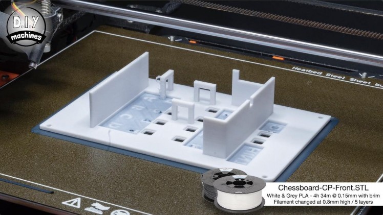
The front of the control panel is 3D printed. The component is called 'Chessbarrd-CP-Front.STL'.
Again I used PLA and switch the filament from the front face of dark grey to a white filament after just five layers / 0.8mm height. (This is worked out when printing with a 0.15mm layer height).
This created the light text outlines for our control panel LEDs to shine through later.
Take the first of your ten 6x6mm tactile switches and lower it into position from the rear of the print. You may need to raise the print to allow the button to sit all the way in. They should also be orientated so that their legs protrude from the sides of the buttons as opposed to the top and bottom (again take a glance at the photos above). They can be held in with some dabs of glue and then time should be given to ensure the glue has dried well.
Take good care when applying the glue, we don't want any of it running to the front of the control button and interfering with the operation of the button when it has cured.
Step 11: Wiring the Buttons on the Control Panel

For this step you will need:
- Electrical wire
These button will be connected to our Arduino Nano. To do this we will need to connect some wires to them. First they should all be connected to a common ground and then we can add individual wires to them for connection to the correct pins on the Arduino board.
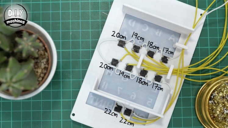
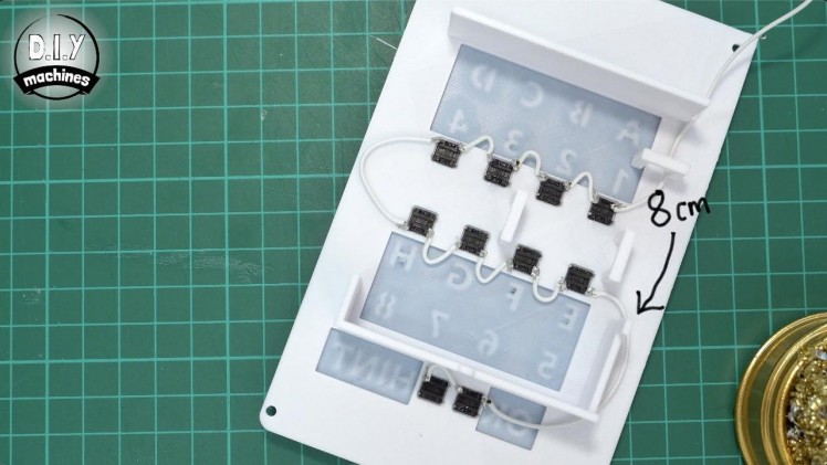
For the ground connection, connect a 18cm long wire to the top right most leg of the most top right button (which is marked as A1 on the front of the control panel). Use some short lengths of wire to hop between the buttons along the top row of legs, then use a 5cm long wire to loop around to the bottom run of legs on the next row of buttons.
Once you have finished going from left to right along the second row of buttons, use an 8cm length of wire to loop around to the last row and then one more short wire to connect the bottom two buttons together.
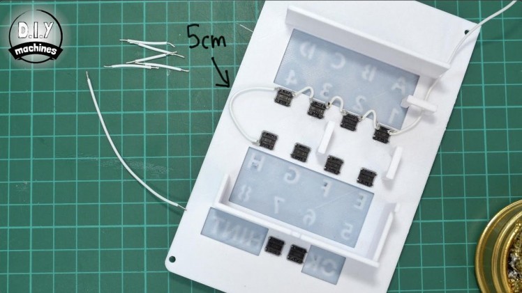
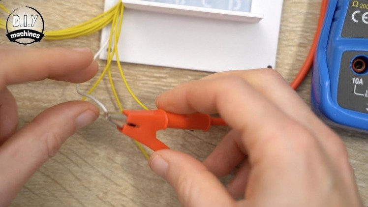
For connecting to the Arduino we need to attach an additional separate wire to each of the buttons. To keep track of which wire is connect to which button you can either label them as you go or use a multimeter later in the next step to work it out.
To help you out I have drawn out what I found to be ideal lengths in the photo above with the yellow wires. Use this as your guide as to which length wire should connect to which button. Once all these additional wires have been added they can be threaded through the 3D printed hoops to keep them tidy.
Step 12: Identifying Wires With a Multimeter
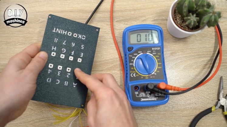
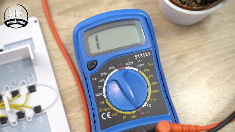
For this step you will need:
- Multimeter
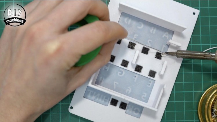
If you labelled your wires as you added them in the previous step then you can skip this step, otherwise to identify the wires set your multimeter to the continuity setting.
Connect one of your probes to the buttons common ground wire (white in my case) and then the other probe to one of the unidentified wires.
You can then press each button on your control panel in turn until you see a reading on the multimeters screen and most likely hear a beep. This is the wire associated with this button. Just repeat this as you go. Now onto the next step...
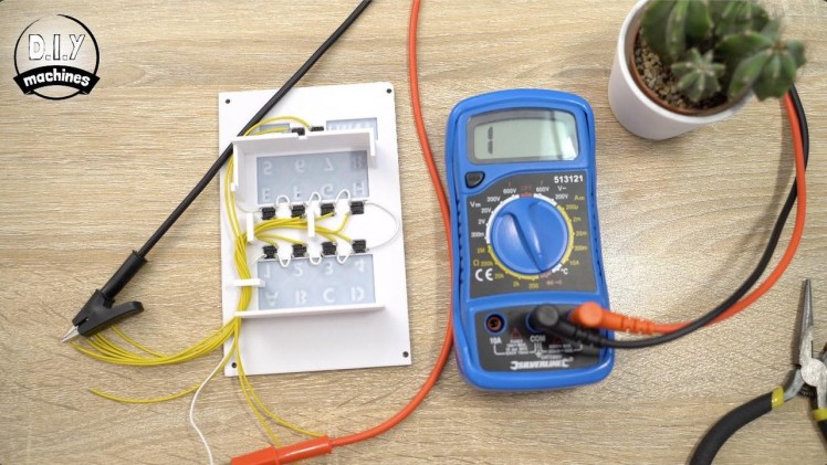
Step 13: Connecting Control Panel Buttons to Arduino
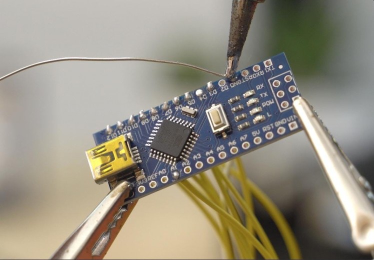
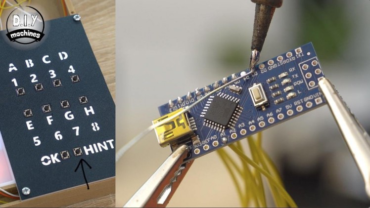

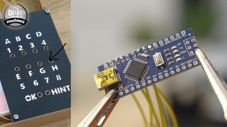

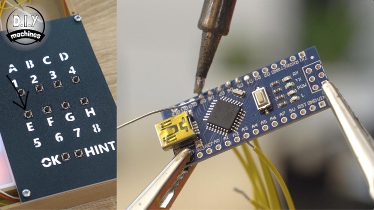


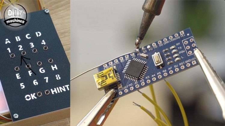
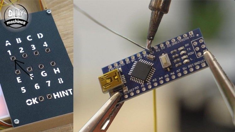

I have re-attached the wiring diagram above for your convenience. The wires from the buttons are soldered onto the Arduino Nano as follows:
- The button for A1 on the control panel connect to D5 on the Arduino.
- The button for B2 on the control panel connect to D6 on the Arduino.
- The button for C3 on the control panel connect to D7 on the Arduino.
- The button for D4 on the control panel connect to D8 on the Arduino.
- The button for E5 on the control panel connect to D9 on the Arduino.
- The button for F6 on the control panel connect to D10 on the Arduino.
- The button for G7 on the control panel connect to D11 on the Arduino.
- The button for H8 on the control panel connect to D12 on the Arduino.
- The button for 'OK' on the control panel connect to A1 on the Arduino.
- The button for 'HINT' on the control panel connect to D3 on the Arduino.
- Then the buttons common ground wire can be connected to any one for the ground pins on the Arduino.
Step 14: Backlighting the Control Panel - Preparing LEDs

For this step you will need:
- Electrical wire
- The roll of RGB LEDs
The control panel for our smart chessboard uses selective backlighting to intuitively communicate what the player is expected to input or press at any particular time. For example the 'hint' button does not light up until a hint is available from the chess computer, and the co-ordinate buttons are not illuminated whilst we wait for the computer to return its move.
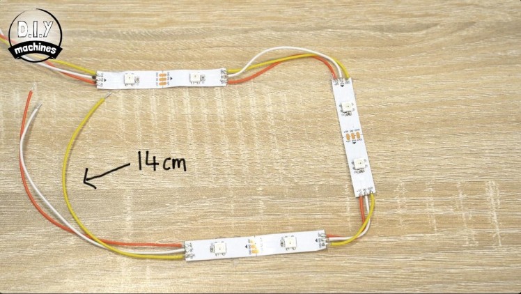
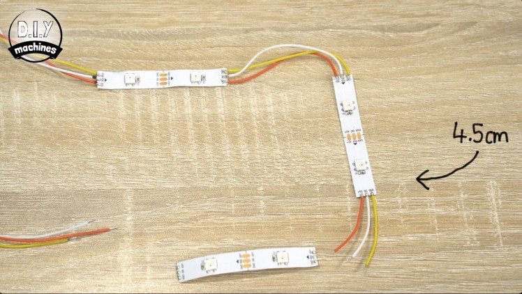
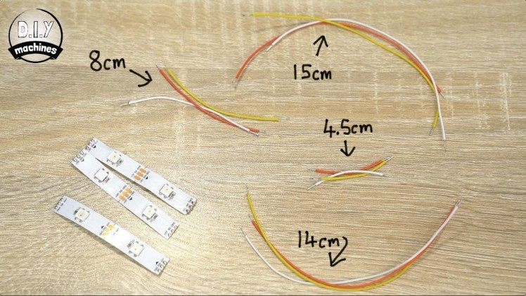
To add the backlighting you should prepare three lengths of two LEDs and pre-tin the three pads at both ends just as we did with the first LED strips used for the chessboard's surface earlier.
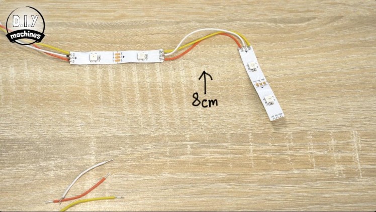
Solder a trio of 15cm long wires to the first LED strip (don't forget to pay attention the direction of the arrows on the LED strips as you go). A trio of 8cm long wires then connect the first strip to the second, followed by 4.5cm wires to connect the third strip which itself then has three 14cm long wires attached to its exiting set of pads.
The last 14cm wires will be used later to connect this chain of LEDs to the LEDs used to backlight the co-ordinate labels around the edges of the board so you can read them more easily in low light situations.
Step 15: Backlighting the Control Panel - Attaching LEDs
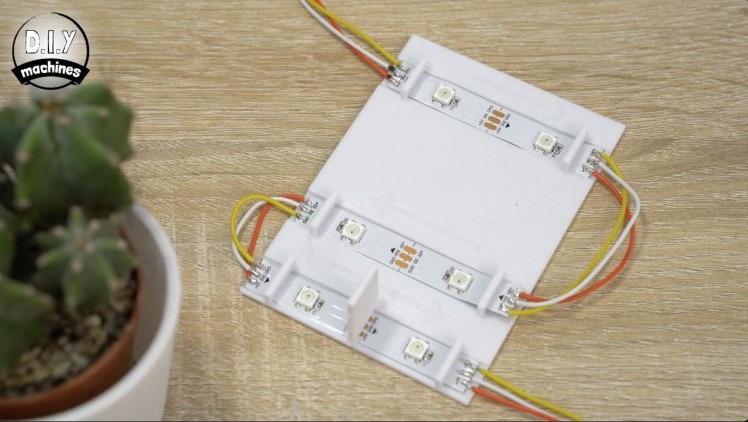
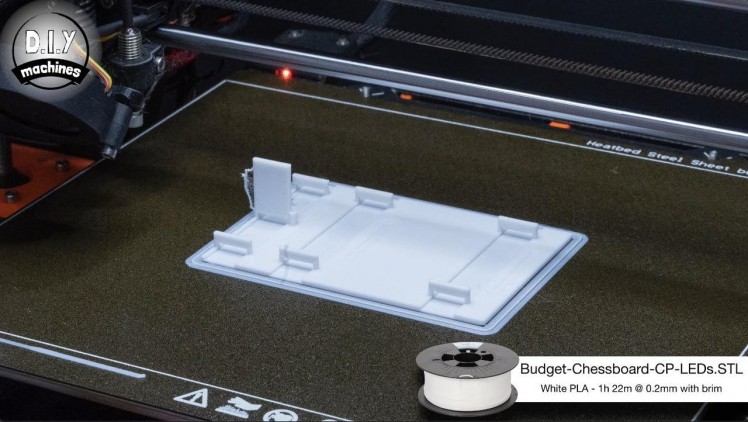
There is a 3D printable part named 'Budget-Chessboard-CP-LEDs.STL' which you need to print. The colour here is not super important but I went with white to help boost the amount of reflected light to the back of the control panel and to avoid any colour casting a coloured print may introduce.
Remove the self adhesive backing from the first pair of LEDs we soldered to and then pass them beneath the two bridges and fix in place at the top of the print. As with the main chessboard there are arrows next to each lane which show you which way the arrows on your LED strips should be pointing.
Repeat this threading the LEDs back and fourth and fixing into place using their self adhesive backs. The little bridges they pass under are there to help prevent them from becoming unstuck and the large fin at the bottom is there to ensure we can light up either the 'OK' or 'HINT' button without lighting up the other unintentionally.
Step 16: Connecting Some More to the Arduino


For this step you will need:
- Electrical wire
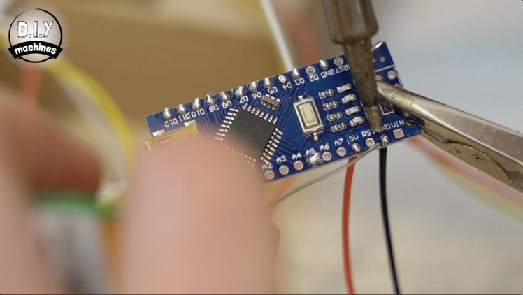
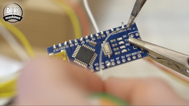
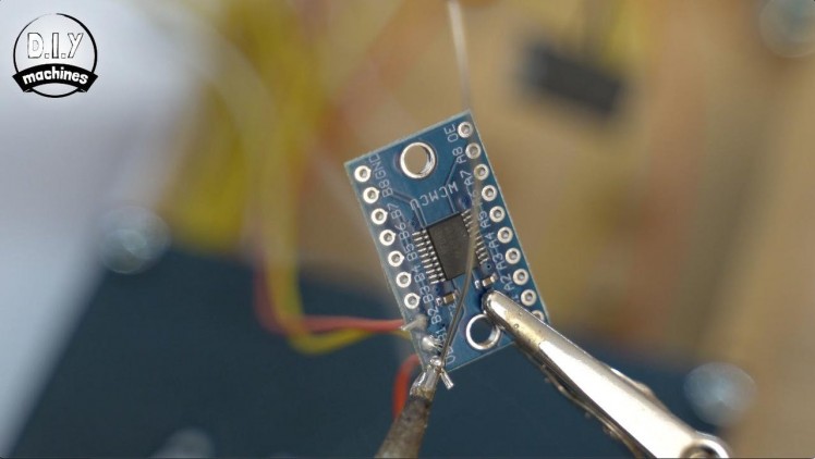
To connect the control panel LEDs to our Arduino we simply need to solder the central digital signal wire to the pin D4 on the Arduino. Whilst we have the soldering iron on we can take the opportunity to connect the data pin for the LEDs in the main chessboard (found in the bottom right) to pin A5 on the Arduino.
We can also add more two wires to the Arduino. Solder a seperate 15cm wire to each of the Arduinos serial pins. These are labelled as 'RX0' and 'TX1'. We will use these in a later step.
Attach two more wires, this time 7cm long to the '5V' and one of the unused 'GND' connections on our Arduino.
Step 17: Fitting the Control Panel Assembly
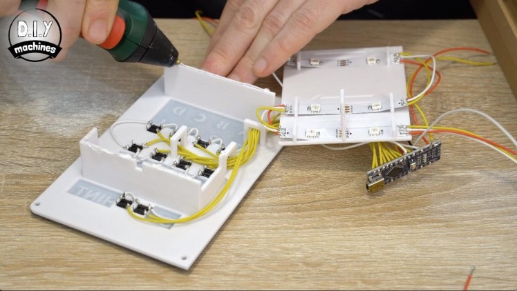
Apply some glue along the top edges of the fins on the back of the control panel front (the part we fitted the buttons into earlier). The LED assembly can then be flipped over and attached to the rear of the control panel.
There is a small tab on the tallest fin on the LED assembly, and a notch in the button assembly. These are here to help you align the two halves.
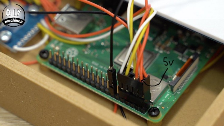
Step 18: Connecting the Ground and 5V Wires

For this step you will need:
- Wiring blocks (x2)
As we need to interconnect all the ground wires and 5v wires together in order to power our Arduino, Raspberry Pi, LEDs and logic shifter we will use two small wiring blocks. I used the Wago ones listed in the BOM at the start of this guide, they're really compact which is ideal for the small enclosure.
To the first block connect the 5v wires from:
- Arduino Nano
- Both ends of the chessboard LEDs
- The top end of the control panel LEDs
To the second block connect the ground wires from:
- Arduino Nano
- Both ends of the chessboard LEDs
- The top end of the control panels LEDs
Step 19: Fitting the Control Panel

For this step you will need:
- M3x6 bolts (x4)
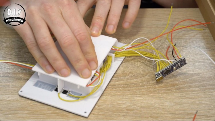
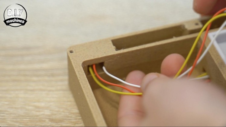
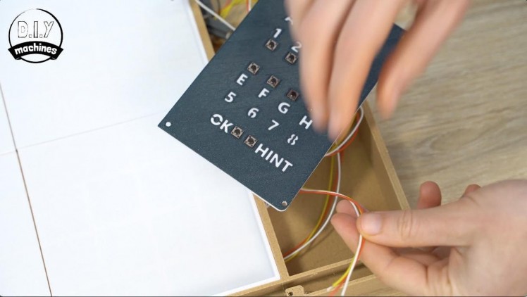
Coming out from the bottom of our control panel are a set of three unconnected wires. These should be threaded through the tunnel at the bottom of the control panel recess in the main chessboard.
Use four of our M3x6 bolts to secure the control panel in place whilst ensuring that you do not trap any of the wires.
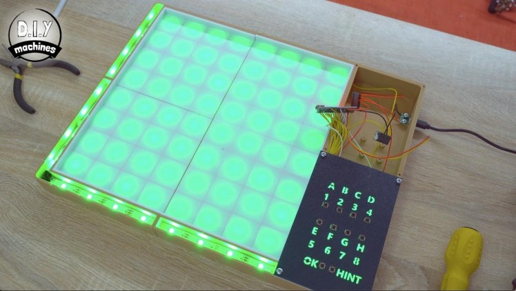
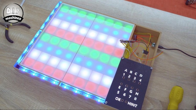
Step 20: Testing the Electronics
For this step you will need:
- USB cable
We should take this opportunity to test the buttons and LEDs we have connected so far. If we find any problems then it will be easier to both troubleshoot and fix now than it will be later.
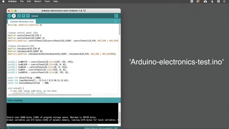
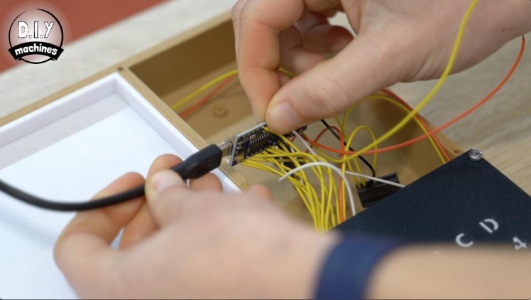
To do this we can upload a test script I created to the Arduino. Connect your Arduino and upload the test script 'Arduino-electronics-test.ino'. (Download the code from Github: https://github.com/DIY-Machines/SmartChess)
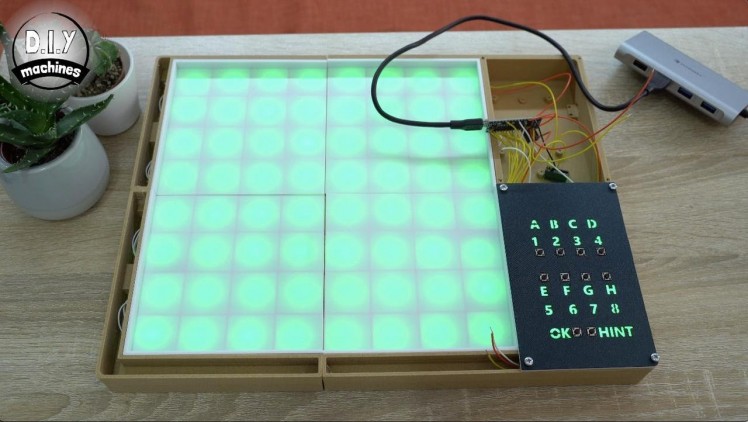
Once uploaded the squares on the chessboard should light up row by row from the bottom in different colours, followed by the control panel buttons lighting up and then everything should turn green.
Don't worry about the brightness of the LEDs at this point. As they are currently being powered by the Arduino Nano and our computers USB port I have limited their brightness. When we upload the final code later and power it from a more capable power source they will be much brighter. :)
Let's work on adding this additional power input next.
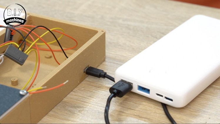
Step 21: Powering the Project Externally
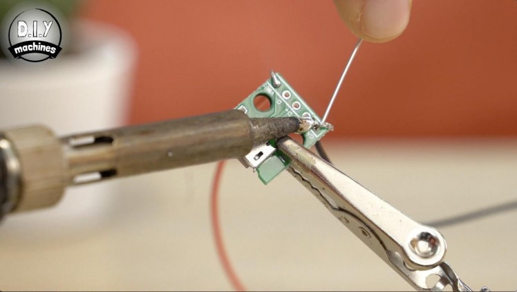
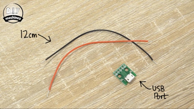
For this step you will need:
- Female USB DIP board
- Electrical wire
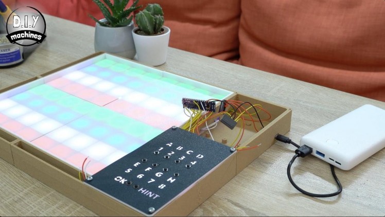
We will mount a female USB port to the side of the board. This will allows us to power it using either a mains power plug when its convenient or with a common USB battery bank when you don't want to be tethered to a wall. I added this so I could play in the garden on the warmer evenings.
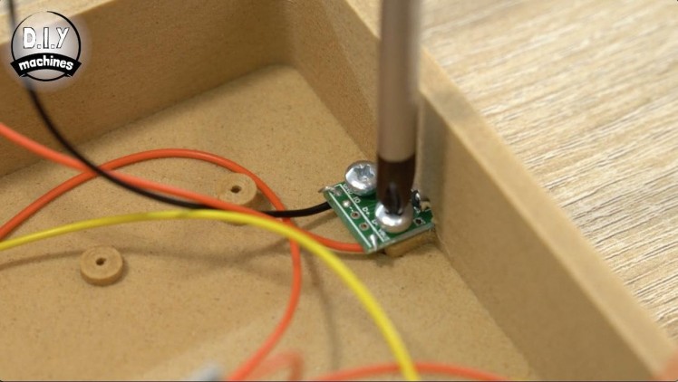
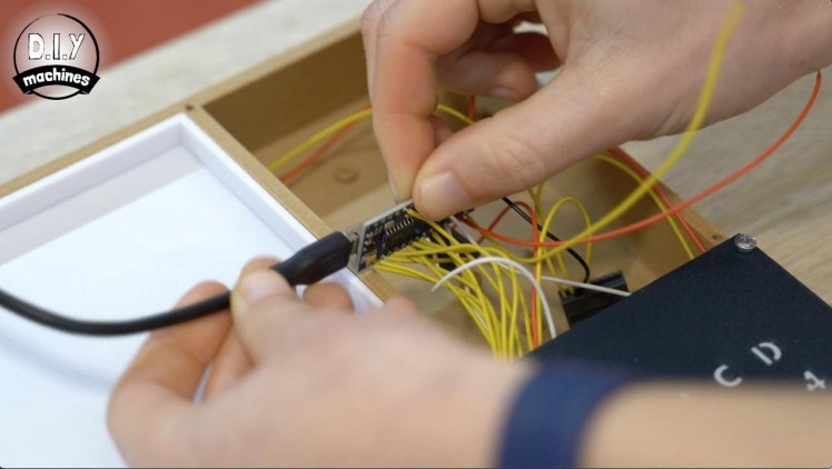
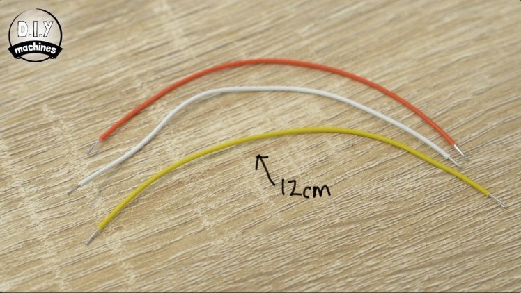
You will need the aforementioned female USB port on a DIP board. Prepare two 12cm wires and solder one to the 'GND' connection of the board and the one the 'VBUS'.
Fix it into place inside the chessboard using two more of the M3x6 bolts and connect the wires now coming from the USB port to their respective power blocks along with the other wires.
We can now connect a USB power source to this new USB port from outside the board and check if the same test LED animation we saw previously play out again. If it does, then we can continue.
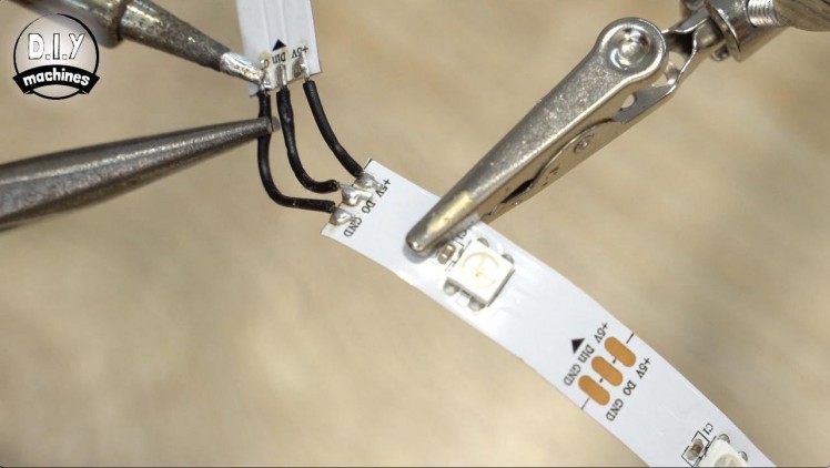
Step 22: Illuminating the Chessboard Co-ordinates
For this step you will need:
- Electrical wire
- The roll of RGB LEDs
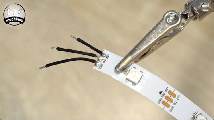
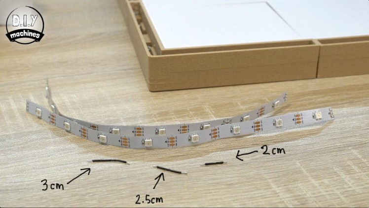
You will need to prepare and tin two more lengths of eight LEDs. The LEDs will need to turn a tight 90 degree corner, to make this easier we can use three wires of differing lengths, one 2cm, one 2.5cm and one 3cm long.
Solder them onto the outgoing end of one of the LED strips with the smallest wire connecting to the '+5V' pad, the 2.5cm wire to 'D0' and the 3m wire to 'GND'.
The second LED strip can then be soldered onto the other end of these wires. You should notice that it already naturally wants to corner.
Take the beginning end of this LED strip and solder it to the three wires coming from the control panel. Don't forget to pay attention to which wire is connect to what - if you are unsure it's worth unscrewing the control panel and checking.
Pass the strip carefully through the tunnel in the first trench running along the front edge of the chessboard. Follow the curve of the wires as you go around the corner and then tuck the second strip under the second tunnel. Use some glue to help keep the LED's fitted flat onto the 3D printed ledge and inline with each row and column on the main playing surface.
Reconnect the USB power supply to run the test script one final time. This time around you should see the additional LEDs light up blue and then green if all has been connected properly.
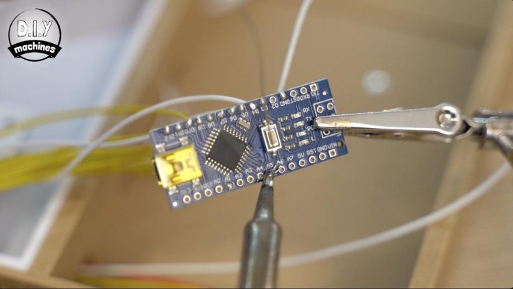
Step 23: Uploading the Final Code to the Arduino
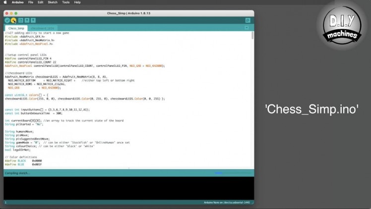
We will soon be connecting additional electronics to the two serial connections on the Arduino Nano. This is extremely likely to interfere with our ability to communicate with the Nano via USB so connect it to your computer again but this time you need to upload the file named 'Chess_Simp, ino'.
Step 24: Configuring the Raspberry Pi


We next need to configure the Raspberry Pi which will involve:
- Flashing the Raspberry Pi OS onto the SD card
- Configuring it heedlessly to connect to wifi and accept SSH connections
- Installing Stockfish (the chess engine)
- Downloading the code I've written for the project from Github
- Installing other needed third party libraries
- Configuring the serial connection between the Pi and Arduino
- Setting it up to start the software automatically after it boots
- Bonding two boards together if your making two to play online against a friend or family member
As more people build there own chessboard it is very likely that the code will be refined and improved over time. To save me having to keep it up-to-date in several places allover the internet I have written the software steps out in detail on my website. You can find them here: https://www.diymachines.co.uk/smart-chess-board-w...
Please follow this steps for preparing your Raspberry Pi's software and then return back here to finish following the remainder of the build process.
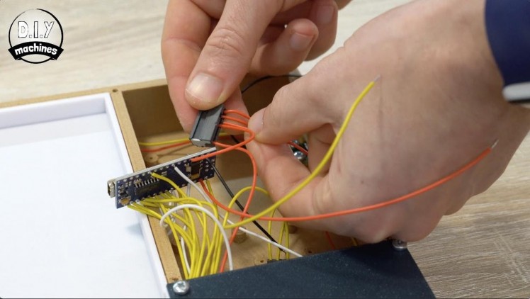
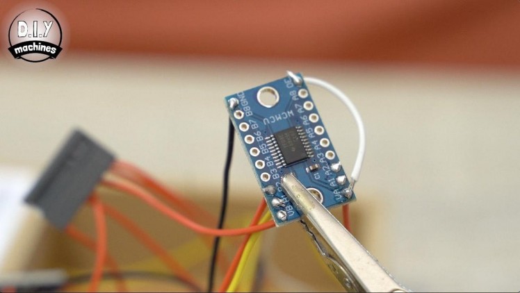
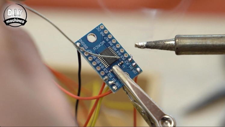
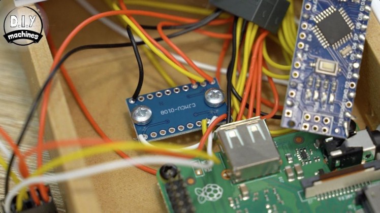
Step 25: Connecting the TXS0108E


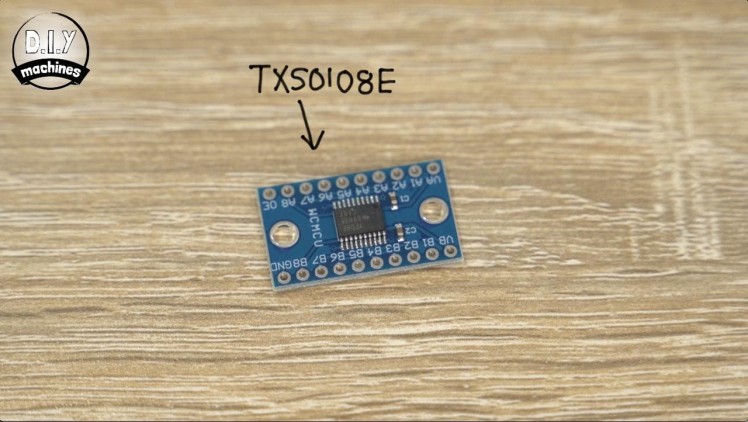
For this step you will need:
- Logic Level Converter - TSX0108E
- Electrical wire
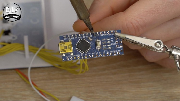
Taking our Logic Level Converter (LLC), the TSXS0108E, we can begin to connect it with our other electronics.
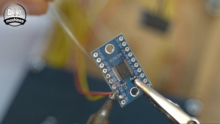
The first wire to attach to it is the wire coming from 'TX1' on the Arduino to pin 'B1' on the LLC. Then the wire coming from 'RX0' is soldered to 'B2' on the LLC.
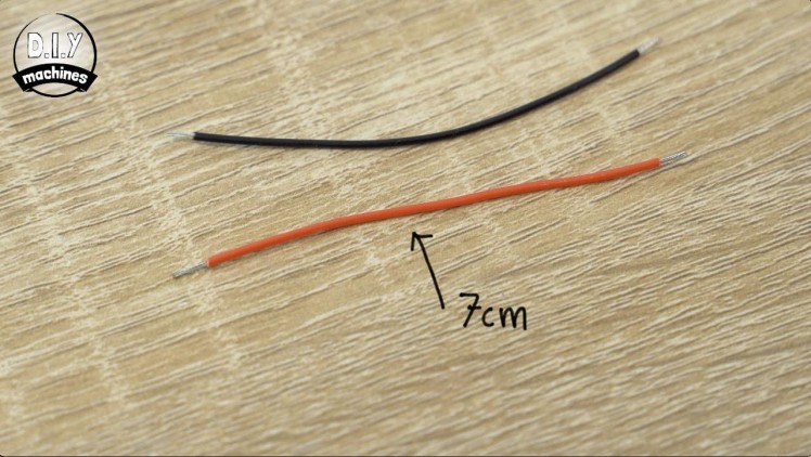
Using two new 7cm long wires, attach one to 'VB' and connect the other end of this cable to the 5V power block alongside our other 5v connections. The second 7cm wire should be soldered to the 'GND' pin on the LLC and connected to the ground power block.
In preparation for connecting the LLC to our Raspberry Pi you need to attach new 12cm long wires to 'VA', 'A1', and 'A2' on the LLC.
Finally we need to connect 'OE' (for Output Enable) to 'VA'. Both of which are on the LLC. I have done this with the short white wire in the photos above.
On a slight side note - if you're curious and wanted to know some more about using the TXS0108E Logic Level Converter then I made a separate mini-guide specifically on that component which you can find here: https://youtu.be/f7aySy_0URE and I also added it to the media for this step.
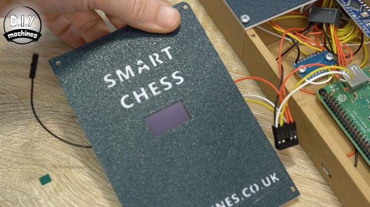
Step 26: Preparing the OLED Screen
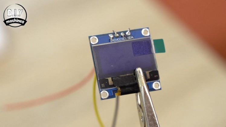
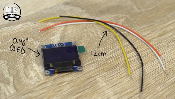
For this step you will need:
- Electrical wire
- 0.96" OLED screen
To prepare our OLED screen for use latercut, tin, and then connect four 12cm long wires to the holes marked as 'GND', 'VCC', 'SCL' and 'SDA'.
Step 27: Preparing to Connect to the Raspberry Pi
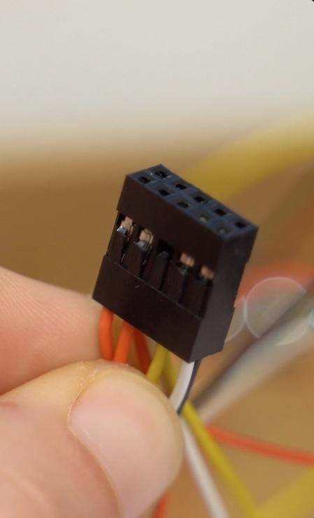
The only thing left to connect now is our Raspberry Pi. I’m going to connect the other ends of the wires we’ve been preparing using a DUPONT style connector. These are easy to make for yourself. In fact, here is another video I made to help you: https://youtu.be/jET1QTP1B7c :)
If you don’t want to use a connector or you're using a Pi without headers you can solder directly to the pins instead. Otherwise, read onto the next step and I'll step you through wiring up the connector.
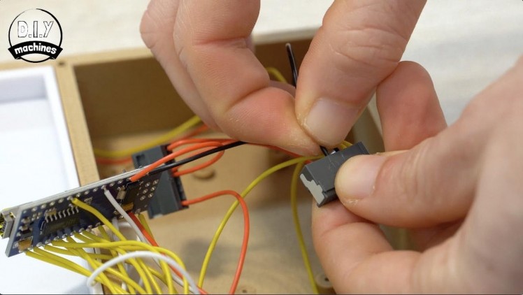
Step 28: Assembling the Connector

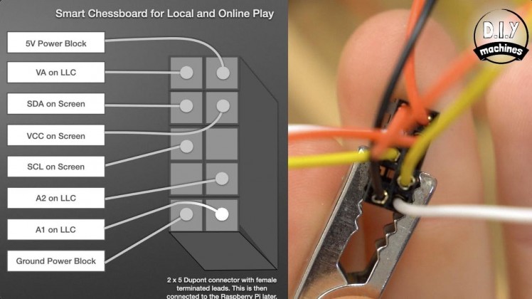

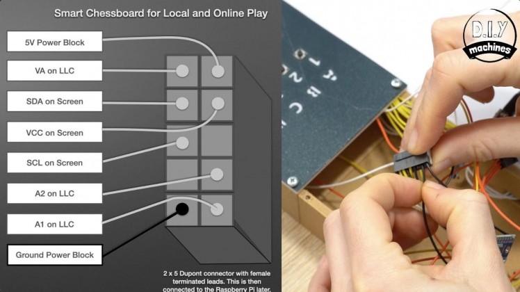
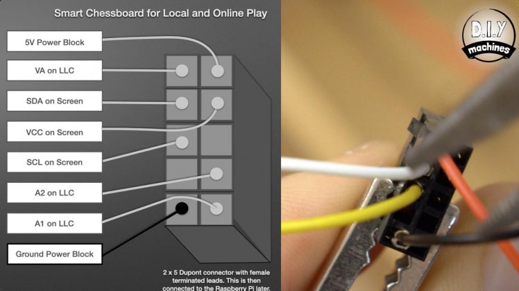

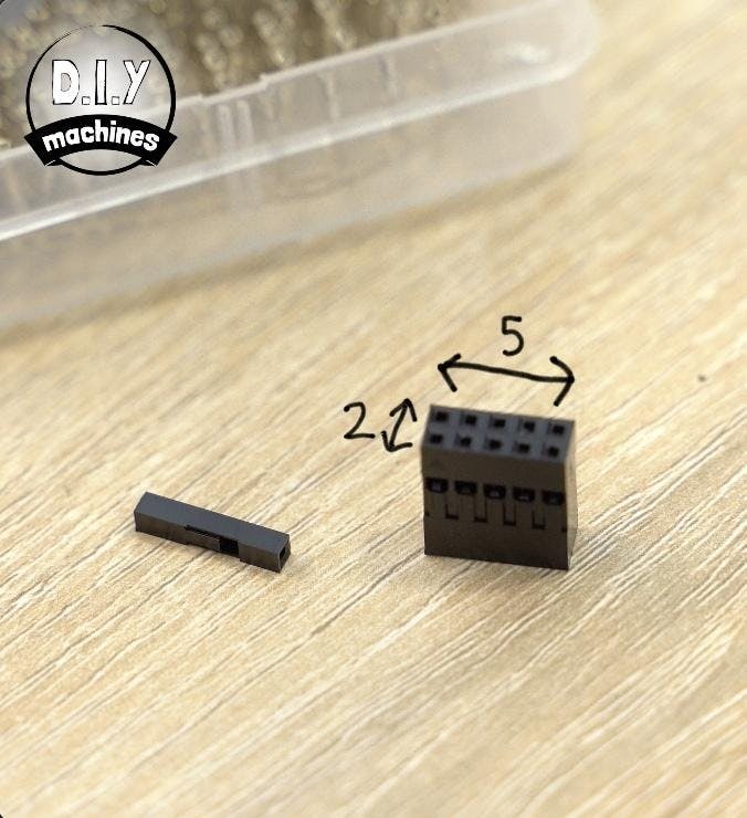
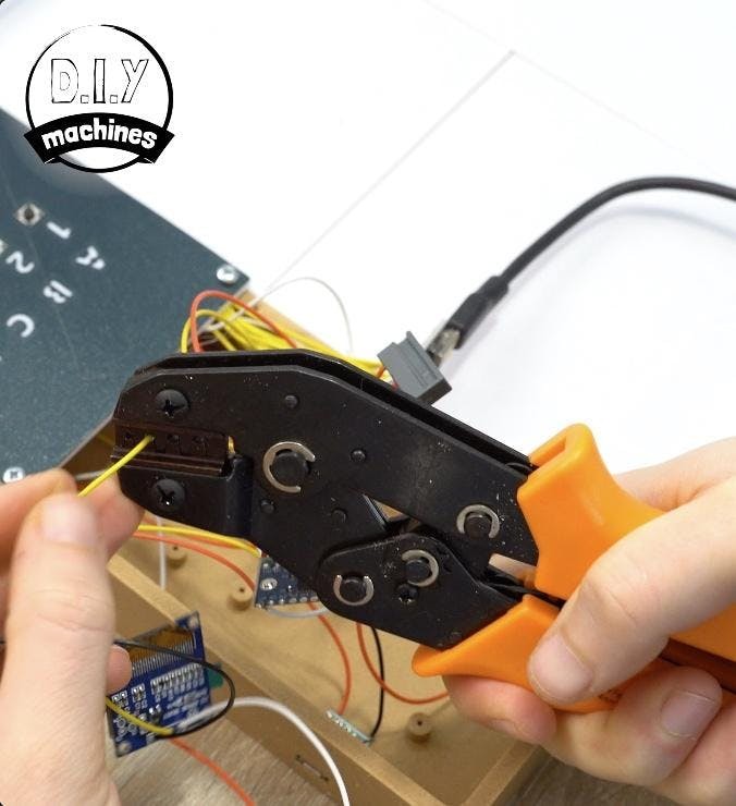
You will need to first add female metal Dupont crimps to then connected ends of the following wires:
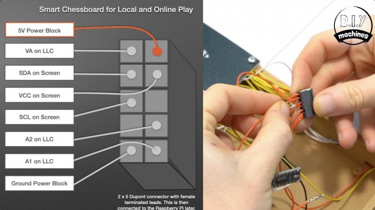
- 5V Power Block (Create a new wire about 12cm long for this)
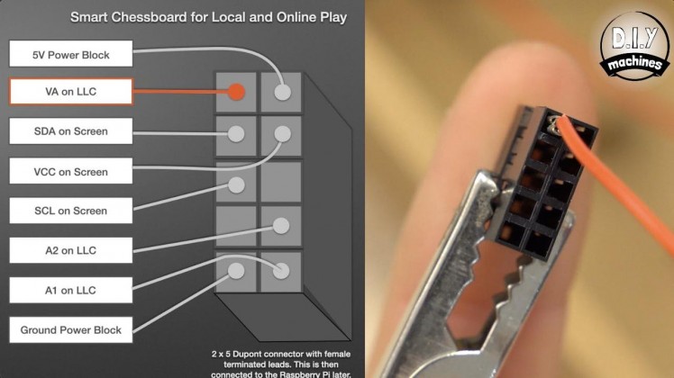
- VA on the logic level converter
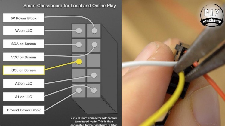
- SDA on the screen
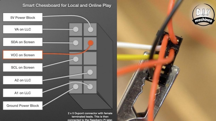
- VCC on the screen
- SCL on the screen
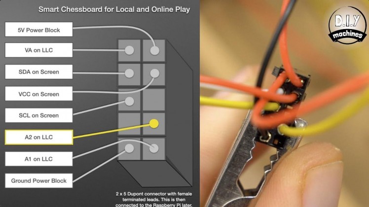
- A2 on the logic level converter
- A1 on the logic level converter
- Ground power block (Create a new wire about 12cm long for this)
The position we insert them to in the connector matters as this will dictate which pin on the Raspberry Pi they connect to.
When looking at the back of the 5x2 Dupont housing the top left most pin wire should be the VA wire from the LLC. The wire below this should be the SDA wire coming from the OLED screen, which is followed immediately below by the SCL wire for the screen. We then skip the next hole and into the bottom left most hole insert a new wire and then connect this to the block of ground wires.
Going over to the right hand side and starting at the top again we will use one of our new wires to connect this pin to the 5V power block. Below this add the screens VCC wire, skip the third hole and the wire coming from A2 on the LLC to the fourth hole with the remaining wire for A1 on the LLC going into the bottom right position.
The only wire which is yet to be connected to something should be the ground wire on the screen. This can be inserted into its own single point Dupont housing.
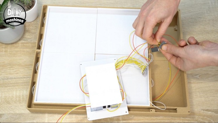
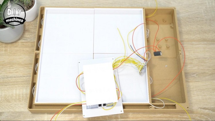
Step 29: Secure the Raspberry Pi and LLC
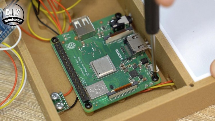
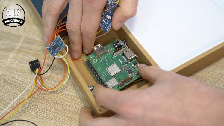
Ensure you have the micro SD card still inserted into the Raspberry Pi and then fix it to the four standoffs in the printed chessboard using the four 2.5mm screws.
Use two M3x6 bolts to secure the LLC just below the Raspberry Pi.
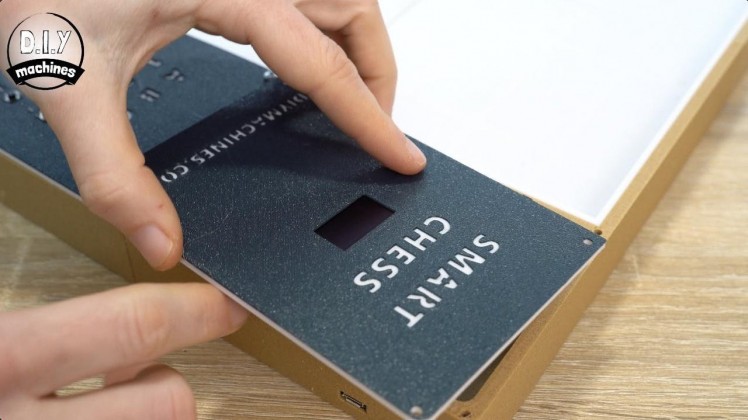
Step 30: Fitting the Screen

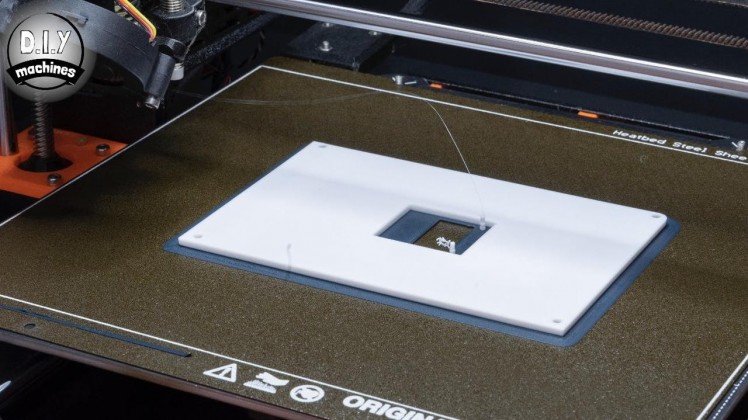
The screen is fitted into another 3D print. This file is called 'Budget-Chessboard-Screen-Front.STL' and just like with the front of the control panel for the LEDs I switched filament after a few layers so that the text on front is legible (though this section is not backlit) and so that the edges for the print match the rest of the edges around the remainder of the chessboard.
Once printed, any protective film that might be on the front of your screen can be removed and the screen is then place face down using the printed lugs to guide it into position. The wires should be towards the top of the print. Use some glue from the reverse side to secure it into place.
Step 31: Connecting the Raspberry Pi
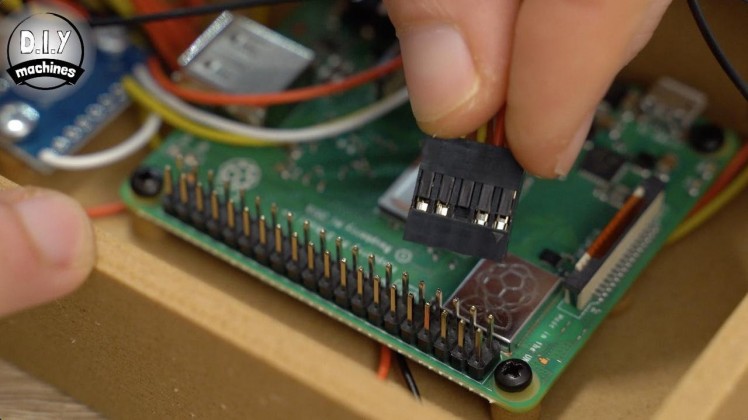
The largest of our Dupont connector can now be slid onto the correct pins on the Raspberry Pi. Identify the 5v wire in the connector (this should be connected to the 5V power block) and ensure this is connecting to the Rapsberry Pi's 5V pin which is in the top right corner when looking at the Pi with it's USB port at the bottom and SD card slot at the top.
The single ground wire for the screen is connected to one of the ground pins on the Pi which is the seventh pin down on the outside edge of the board. This would leave a gap of one pin below the larger connector.
Step 32: Fit the Lid
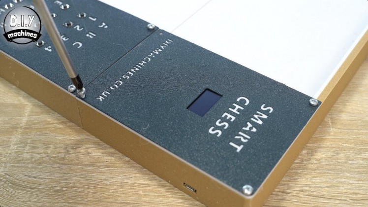
The screen assembly can now be fitted to the top side of the board. Ensure that you don't trap any wires and then use your last four M3x6 bolts to secure it in the four corners.
Step 33: Labelling the Co-ordinates
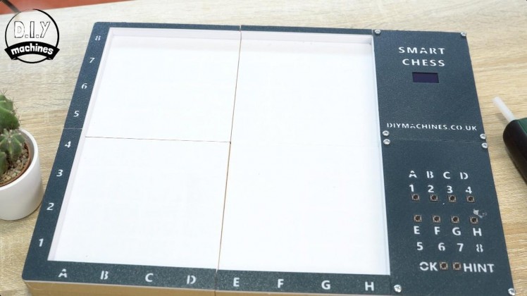
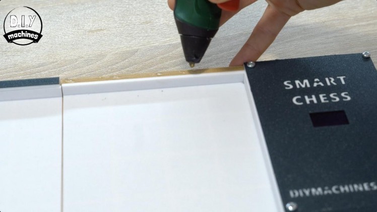
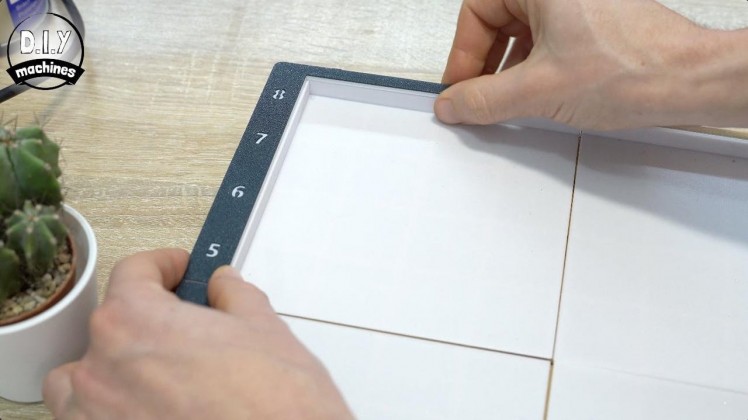

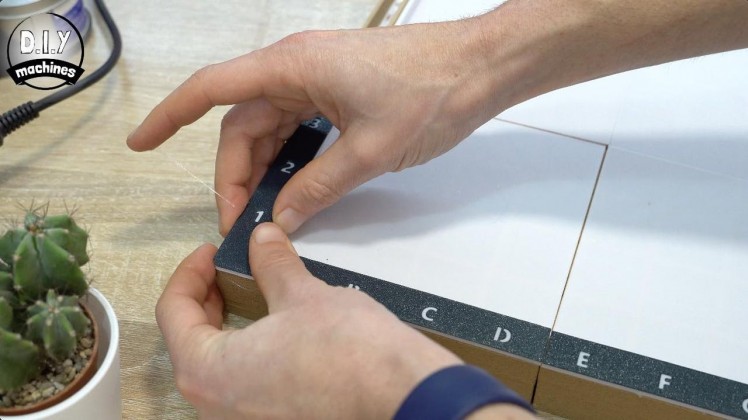
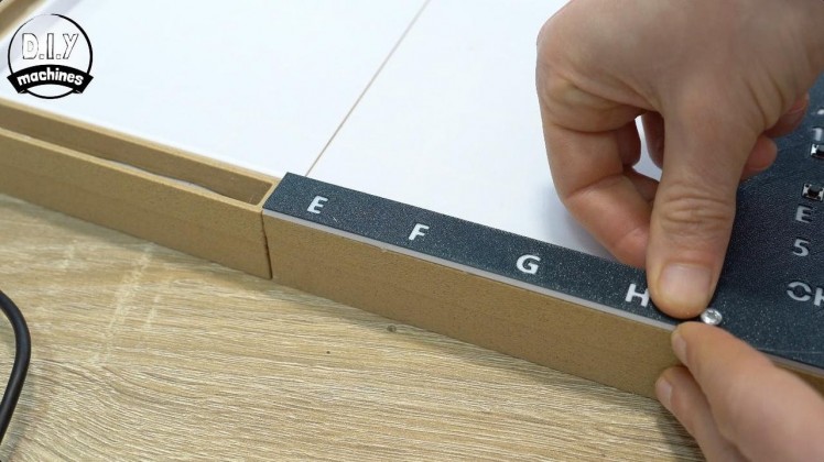
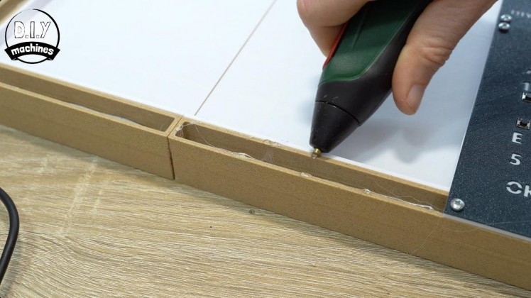
The last thing we need to do is print the labels for the co-ordinates around the board and then fit them.
As these are backlit using the LEDs we installed earlier I printed them the same as the other fronts to the control panel and changed the filament from the darker grey colour to light transmitting white after 0.8mm / 5 layers (when printing at 0.15mm layer height).
Add some glue to the chessboard and then fit the label in place. I would recommend laying them 'dry' without glue first to see how they sit and then fit them one at a time so you can concentrate on their position as the glue dries/cools.
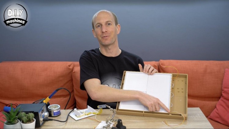
Step 34: Project Complete!


Great work making it to the end. If you also wanted to 3D print your own chess pieces for this board then you'll find a perfectly sized set available here: https://selz.co/xA08oo3
They are designed for 3D printing in resin or traditional FDM. None require supports to be added with the exception of the knight - but it's worth it.
Should you want to support my projects, please consider subscribing to me on here and Youtube. I also have a Patreon page where some very kind people are helping me to cover the cost of designing, documenting and sharing these projects. Please consider joining them in any way if you can.
Until the next project, ciao for now.Lewis
Schematics, diagrams and documents
CAD, enclosures and custom parts
Code
Credits
Related products


Leave your feedback...