
Diy Home Automation Using Arduino Uno R4

Made by jithin / Home Automation / Lights / IoT
About the project
Making a home automation system using Arduino UNO R4 WiFi
Project info
Items used in this project
Hardware components

Story
DIY Home Automation using Arduino UNO R4
Welcome to this beginner's guide to making your own home automation system, leveraging the prowess of an Arduino Board, Arduino IoT Cloud, and the convenience of mobile phone control.
Delving into the realm of home automation opens doors to streamlined living, where diverse devices can be managed effortlessly and conveniently. In the following comprehensive tutorial, we will navigate you through the process of assembling and configuring an Arduino-based system, empowering you to remotely oversee and manipulate devices through the amalgamation of internet power and smartphone finesse. Prepare to embark on this journey, culminating in the creation of a futuristic, interconnected domicile.Components Required Smart Home
The foundational component is an Arduino Board sporting Wireless connectivity. In this project, I'll be employing the Arduino UNO R4 WiFi variant. Equipped with a Renesas RA4M1 32-bit Cortex®-M4 CPU, this elevated iteration of the esteemed Arduino UNO board boasts novel attributes such as wireless connectivity, USB type C connector, 5V operating voltage, and backward compatibility with legacy sensors and libraries. For a deeper dive into its features, refer to our preceding video expounding on Arduino specifics.
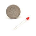
The roster of necessities extends to resistors, LEDs, MOSFETs, and interconnecting wires. A breadboard is also requisite for preliminary testing.
The Smart Home Circuit
Let's now unveil the circuit configuration and its components. The assembly comprises an Arduino unit, several MOSFETs, 7805 voltage regulators, LEDs, and header pins. Among these, a header pin designated for voltage input is pivotal. This input, sourced from a 9-volt battery or a 12-volt DC adapter, interfaces with a 7805 voltage regulator, converting the Vin into a stable 5V DC supply, amenable for numerous device connections.
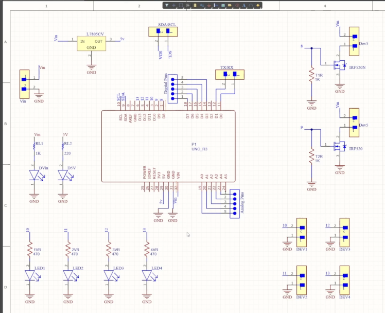
Prominent in the Arduino Home Automation Circuit are two MOSFETs functioning as switches, linked to Arduino's pin 8 and pin 9. Manipulating these pins empowers control over the MOSFETs, thereby initiating or halting circuit flow. Terminal blocks tethered to these MOSFETs facilitate connectivity with electronic devices, leading to circuit closure or opening, contingent on MOSFET states.
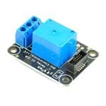
Further terminal blocks, connected to Arduino's pins 10, 11, 12, and 13, present an avenue to interface with 5V operating voltage devices. Optionally, these points can accommodate a 5-volt relay for experimentation with AC devices.
A standout feature of this Arduino board is its 5-volt operating voltage, ensuring compatibility with sensors and modules suited for its predecessor. For any external sensor or module integrations, the available header pins serve as valuable connection points.
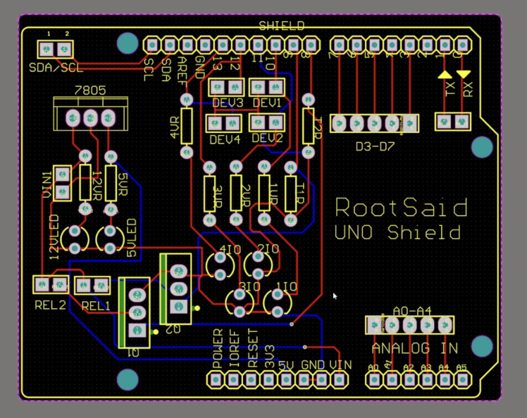
Creating the Arduino Home Automation PCB
Once the circuit design culminates, I undertook the task of devising a compact PCB using Altium. This structured layout accommodates the seamless arrangement of all components. Noteworthy is the dual-layer nature of this PCB, evidenced by routing on both sides. The utilization of Altium PCB Designer's interactive routing strategies accelerates track creation within PCBs.
The next phase involves procuring the PCBs from PCBWay, a specialist in PCB prototyping, limited-volume production, and tidy PCB Assembly.
To initiate this process, visit the PCBWay platform, input core board details within the instant order form, and proceed to furnish more elaborate specifics within the ensuing form. This will lead to uploading the Gerber file for review. Subsequent steps encompass adding the design to your cart, executing the payment, and anticipating PCB delivery.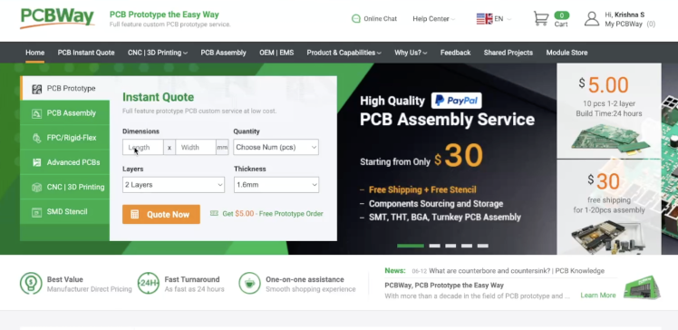
With components and PCB in hand, the assembly proceeds. Each component is meticulously soldered onto the PCB, with keen attention to component polarity. The resulting PCB assembly embodies meticulous workmanship.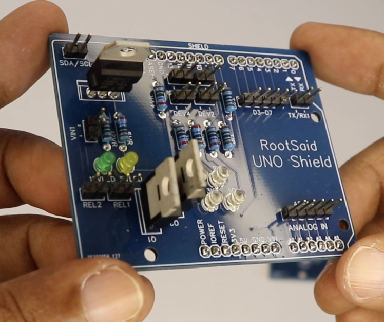
Software Configuration through Arduino IoT Cloud
Transitioning to the software facet, the Arduino IoT Cloud becomes the focus of programming endeavors. Encompassing home automation setup entails accessing the Arduino IoT Cloud and logging in using your credentials. Beneath "things," your linked projects materialize. In this context, "Arduino Home Automation" represents the configured project.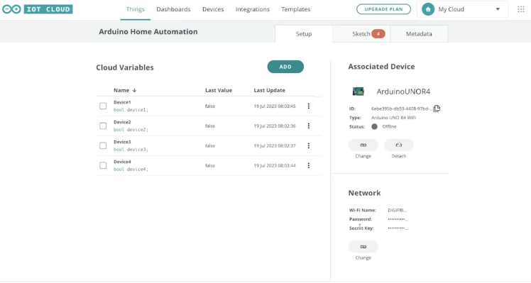
Within this sphere, properties germane to the project manifest. The presence of four Cloud variables—device1, device2, device3, and device4—is evident. This project converges with the earlier introduced Arduino Uno R4.
Setting Up Home Automation using Arduino IoT Cloud
For those unfamiliar with programming Arduino boards via Arduino IoT Cloud and managing them through browsers, our antecedent instructional video outlines the entire process. For in-depth comprehension, indulge in the video and progress onward.
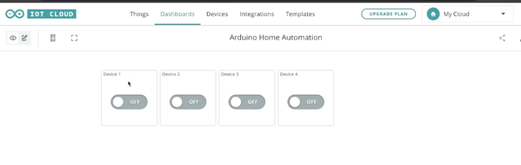
Additionally, network configurations have been articulated. The rationale behind the four variables pertains to overseeing four devices. Navigating to the dashboard, you'll be greeted by four buttons.
These buttons correspond with the four earlier-mentioned variables. Toggling a switch transforms the value of device1, altering its state to "True" for activation and "False" for deactivation. Perusing the code and sketch affords insights into the underlying logic.
Deciphering the Code
A perusal of the code reveals the preemptive declaration of the four variables. Within the setup function, serial communication initiation and the designation of output pins for pins 10, 11, 12, and 30 transpire. These pins govern LEDs, interfaced through header pins. Subsequently, Wi-Fi connectivity to the previously configured network is established.
The loop function continually monitors the four variables—device1, device2, device3, and device4. Any variation in their states triggers respective functions like onDevice1Change() and onDevice2Change(). The functions are designed to manipulate the pins based on variable states, thus influencing LED states.
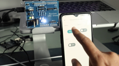
Uploading the Code and Testing
Uploading the code onto your Arduino board, followed by monitoring through the serial interface, ensures a successful connection with Arduino IoT Cloud. With successful integration, the dashboard becomes your control panel. Through it, you can sequentially activate and deactivate LEDs via switches linked to respective variables. This manipulation extends to mobile devices as well, courtesy of the Arduino IoT Cloud app. Installing the app, connecting to your account, and accessing the dashboard allows seamless remote control through smartphone interaction.
Schematics, diagrams and documents
Code
Credits
Related products


Leave your feedback...