
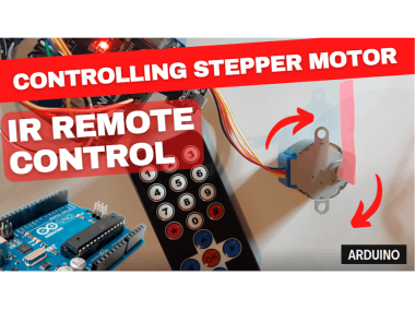
Controlling Stepper Motor 28byj-48 With Ir Remote & Arduino

Made by Ron / Home Automation / Robotics / Sensors
About the project
In this tutorial we are going to learn how to control a Stepper motor using IR remote and Arduino.
Project info
Difficulty: Moderate
Platforms: Arduino, Digilent, Visuino
Estimated time: 1 hour
License: GNU General Public License, version 3 or later (GPL3+)
Items used in this project
Hardware components

Story
If you press & hold on the remote a Left or Right button the Motor will spin as long as you hold the button on the remote. If you press once a button Down or a button Up, the motor will start to continuously spin left or right.
Watch the Video!
Step 1: What You Will Need1 / 6
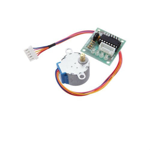
- Stepper motor 28byj-48 & stepper motor driver board
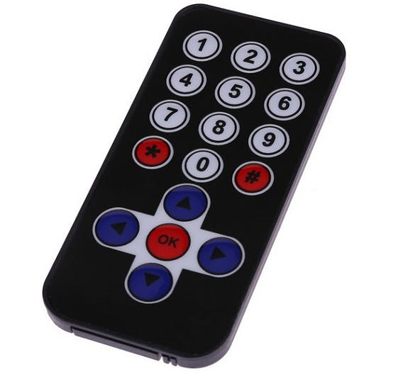
- IR Remote Sender
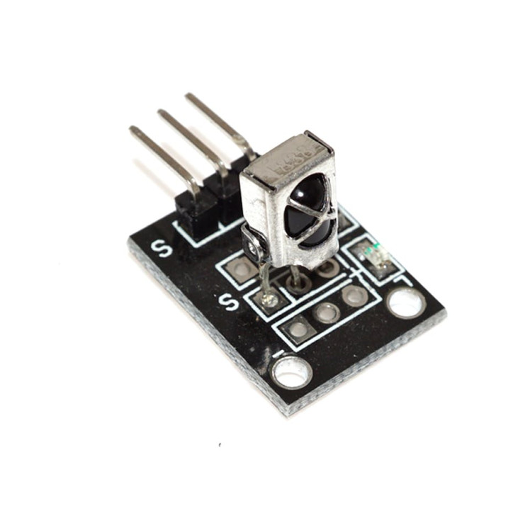
- IR Receiver module
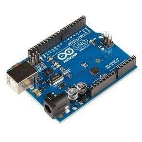
- Arduino UNO (or any other Arduino or ESP)
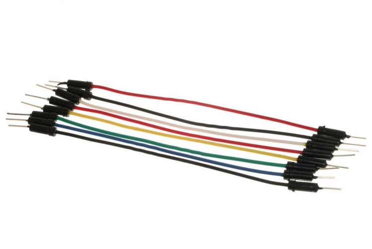
- Jumper wires
- Visuino program: Download Visuino

Thank you PCBWay for supporting this tutorial and helping users learn more about electronics.
What I like about the PCBWay is that you can get 10 boards for approximately $5 which is really cost effective for professional made boards, not to mention how much time you save!
Go check them out here. They also offer a lot of other stuff in case you might need it like assembly,3D printing,CNC machining and a lot more.
Step 3: The Circuit
- Connect IR RECEIVER pin (S) pin to Arduino Digital pin[2]
- Connect IR RECEIVER pin [+] to Arduino positive pin[5V]
- Connect IR RECEIVER pin [-] to Arduino negative pin[GND]
- Connect Stepper Motor to Stepper Motor Driver
- Connect Arduino pin [5V] to Driver Board pin [VCC]
- Connect Arduino pin [GND] to Driver Board pin [GND]
- Connect Arduino digital pin [8] to Driver Board pin [IN1]
- Connect Arduino digital pin [9] to Driver Board pin [IN2]
- Connect Arduino digital pin [11] to Driver Board pin [IN3]
- Connect Arduino digital pin [12] to Driver Board pin [IN4]
1 / 2

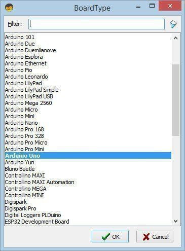
Start Visuino as shown in the first picture Click on the "Tools" button on the Arduino component (Picture 1) in Visuino When the dialog appears, select "Arduino UNO" as shown on Picture 2
Step 5: In Visuino Add Components1 / 6
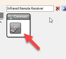

- Add "Infrared Remote Receiver" component
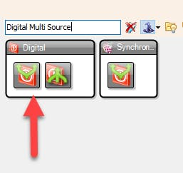
- Add 3X "Digital Multi Source" component
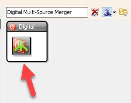
- Add 3X "Digital Multi-Source Merger" component
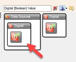
- Add "Digital (Boolean) Value" component
- Add "Toggle(T) Flip-Flop" component
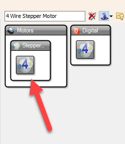
- Add "4 Wire Stepper Motor" component
1 / 11
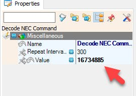
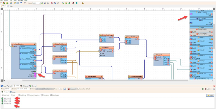
Lets set the commands for the Left & Right, Up & Down button on the Remote, you will need a Code for that, in my case it was 16734885 & 16716015, 16718055 & 16730805 each Remote might use different code, if you do not have it check out the Next step on how to obtain the code.
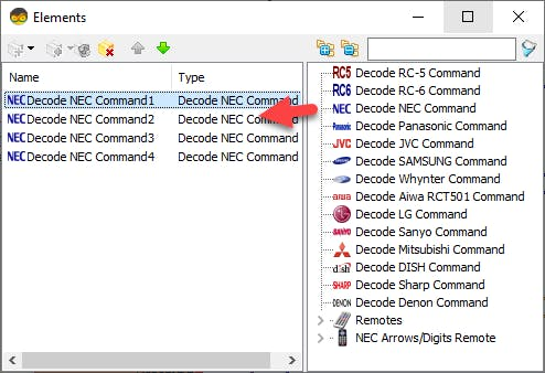
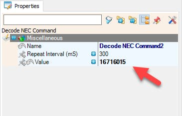
- Double Click on the "InfraredReceiver1" and in the "Elements" window drag "Decode NEC Command" to the Left side and in the properties set Value to 16716015
- Drag another "Decode NEC Command" to the Left side and in the properties set Value to 16734885
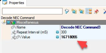
- Drag another "Decode NEC Command" to the Left side and in the properties set Value to 16718055
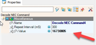
- Drag another "Decode NEC Command" to the Left side and in the properties set Value to 16730805
- Close the "Elements" window
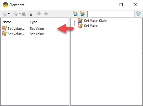
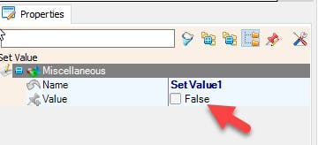
- Double Click on the "DigitalValue1" and in the "Elements" window drag "Set Value" to the Left side and in the properties set Value to False
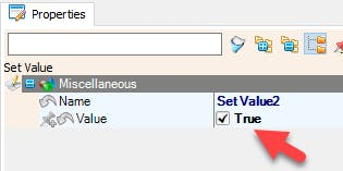
- Drag Another"Set Value" to the Left side and in the properties set Value to True
- Close the "Elements" window
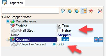
- Select "Stepper1" and in the properties set "Half Step" to False
- Select "Stepper1" and in the properties set "Steps Per Second" to 500
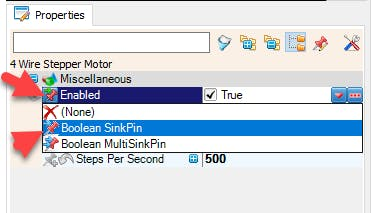
- Select "Stepper1" and in the properties select "Enabled" and click on the Pin Icon and select "Boolean SinkPin"
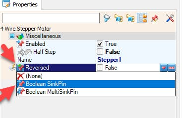
- Select "Stepper1" and in the properties select "Reversed" and click on the Pin Icon and select "Boolean SinkPin"
- Connect "InfraredReceiver1" pin [Out] to Arduino Serial pin [0]
- Upload the Arduino Code & open Serial tab, Select Port & click Connect Button
- Click on the Left & Right, Up & Down button on the Remote and you should see the Codes
1 / 2
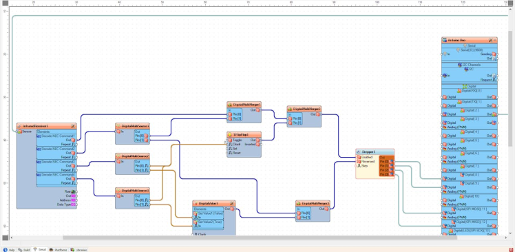
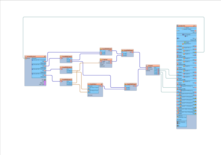
- Connect Arduino Digital pin [2] to "InfraredReceiver1" pin [Sensor]
- Connect "InfraredReceiver1" > "Decode NEC Command1" pin [Out] to "DigitalMultiMerger1" pin [0]
- Connect "InfraredReceiver1" > "Decode NEC Command2" pin [Out] to "DigitalMultiSource1" pin [In]
- Connect "InfraredReceiver1" > "Decode NEC Command3" pin [Out] to "DigitalMultiSource2" pin [In]
- Connect "InfraredReceiver1" > "Decode NEC Command4" pin [Out] to "DigitalMultiSource3" pin [In]
- Connect "DigitalMultiSource1" pin [0] to "DigitalMultiMerger1" pin [1]
- Connect "DigitalMultiSource1" pin [1] to "DigitalMultiMerger3" pin [0]
- Connect "DigitalMultiSource2" pin [0] to "TFlipFlop1" pin [Clock]
- Connect "DigitalMultiSource2" pin [1] to "DigitalValue1" > "Set Value1" pin [In]
- Connect "DigitalMultiSource3" pin [0] to "TFlipFlop1" pin [Clock]
- Connect "DigitalMultiSource3" pin [1] to "DigitalValue1" > "Set Value2" pin [In]
- Connect "DigitalValue1" pin [Out] to "DigitalMultiMerger3" pin [1]
- Connect "DigitalMultiMerger1" pin [Out] to "DigitalMultiMerger2" pin[0]
- Connect "TFlipFlop1" pin [Out] to "DigitalMultiMerger2" pin[1]
- Connect "DigitalMultiMerger2" pin [Out] to "Stepper1" pin[Enabled]
- Connect "DigitalMultiMerger3" pin [Out] to "Stepper1" pin[Reversed]
- Connect "Stepper1" pin [0] to Arduino digital pin [8]
- Connect "Stepper1" pin [1] to Arduino digital pin [9]
- Connect "Stepper1" pin [2] to Arduino digital pin [11]
- Connect "Stepper1" pin [3] to Arduino digital pin [12]
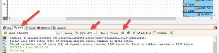
In Visuino, at the bottom click on the "Build" Tab, make sure the correct port is selected, then click on the "Compile/Build and Upload" button.
Step 10: PlayIf you power the Arduino module, and press a Left or Right button on the IR Remote and Hold it the Motor will Turn Right or Left, and if you press a UP or DOWN button on the IR Remote the Motor will start spinning Right or Left each time.
Congratulations! You have completed your project with Visuino. Also attached is the Visuino project, that I created for this tutorial, you can download it and open it in Visuino: https://www.visuino.eu
Schematics, diagrams and documents
Code
Credits
Related products


Leave your feedback...